Communication

Quad-Band Circular Polarized Antenna for GNSS, 5G and WIFI-6E Applications

1
The State Key Laboratory of Complex Electromagnetic Environment Effects on Electronic and Information System, Luoyang 471004, China
2
School of Physics and Electronic Information, Anhui Normal University, Wuhu 241002, China
3
Wuhu CEPREI Information Industry Technology Research Institute, Wuhu 241002, China
4
The School of Marine Science and Technology, Northwestern Polytechnical University, Xi’an 710072, China
*
Author to whom correspondence should be addressed.
Electronics 2022, 11(7), 1133; https://doi.org/10.3390/electronics11071133
Submission received: 13 March 2022 / Revised: 30 March 2022 / Accepted: 31 March 2022 / Published: 2 April 2022
(This article belongs to the Special Issue Evolutionary Antenna Optimization)

Abstract

:
A quad-band circularly-polarized antenna, for applications of a global navigation satellite system (GNSS), 5G, and WIFI-6E, is designed, fabricated, and measured. The proposed antenna is formed by an L-shaped radiator, a rectangular frame ground with an L-shaped stub, and a rectangular strip at the opposite corner. The microstrip antenna can generate four frequency bands, covering WIFI-6E (5925–7125 MHz), 5G n77 (3300–4200 MHz), n78 (3300–3800 MHz), and the GNSS bands. This antenna generates right hand circular polarization (RHCP) waves in the low frequency band (0.95–2.11 GHz), covering GPS, BDS, GLONASS, and GALILEO applications. Moreover, an L-shaped aperture and three rectangular slits are cut on the ground to broaden the axial-ratio bandwidth at the upper band. A prototype is fabricated and measured to verify the performance of this design. It is shown that the agreement between the simulation and measurement is satisfactorily good. The measured −10 dB bandwidths for each band are 75.8% (0.95–2.11 GHz), 55.8% (3.05–5.39 GHz), 39.9% (5.84–8.19 GHz) and 10.3% (9.14–10.68 GHz), respectively. While the measured 3 dB axial-ratio bandwidths are 59.4% (1.16–2.14 GHz), 35.8% (3.23–4.64 GHz), 8.4% (5.70–6.20 GHz), and 2.6% (7.51–7.71 GHz), the measured gains are 4.56, 2.28, 4.26, and 4.30 dBi at 1.5 GHz, 3.8 GHz, 6 GHz, and 7.6 GHz, respectively.

1. Introduction

The circular polarization (CP) antenna is an important component in many communication systems. The investigation into this component has been a hot topic for many years [1,2]. Electromagnetic waves usually encounter reflection and refraction during propagation, which often leads to a change in polarization direction or state [3]. In addition, when travelling through the ionic and rain layers, depolarization effects may occur, which is very harmful to communication links. It is well recognized that a circularly polarized wave is less affected by the Faraday rotation [4,5] in comparison to a linearly polarized one. Moreover, it is superior in countering the depolarization effect. Therefore, circularly polarized antennas are usually used in global navigation satellite systems (GNSS). They also have important applications in various wireless systems, such as radar and mobile communication systems [6].
With the swift development of wireless communication, many functions are integrated into a single terminal device, and multi-band antennas are in active demand. Antennas working over several frequency bands with circularly polarized properties are, therefore, highly preferred. The first requirement may be the coverage of several navigation systems simultaneously; the second requirement is that other wireless communications, such as 5G and WIFE, can be integrated in a single terminal device. In this connection, further investigation into multi-band circularly polarized antennas is required.
For an arbitrary electromagnetic wave, its electric field E can be divided into two components, i.e., E = E x e j φ x e ^ x + E y e j φ y e ^ y . If the amplitudes of the two components are equal ( E x = E y ) and the phase difference meets φ y φ x = ± 90 ° , the resultant field appears as a circularly polarized wave [7]. There are many techniques to realize CP antennas, such as cutting slots [8,9,10], adding branches [11,12], using a feed network with a phase difference of 90° [13,14], etc. In Ref. [14], a polarization reconfigurable antenna was developed for GNSS. The variation in operation frequency is tuned by PIN-diode switches, which are not multi-band operation antennas. A compact antenna was proposed in Ref. [15], through using two T-coupling lines with different lengths as feeds, to achieve circular polarization. It can fully cover the GPS L1 band. Stacking radiating patches is another common method to generate multi-band circular polarization [16,17,18,19]. The main drawbacks of the stacking technique are the difficulty in fabrication and relatively larger thickness, which is not preferred in many mobile terminals. Multi-band circular polarization can also be achieved by etching slots on the ground layer [20,21,22,23]. Most of these designs can provide dual-band operation. In Ref. [24], a circularly polarized antenna is developed based on a dielectric resonator. This antenna can excite six different mixed radiation modes and generate four frequency bands for BDS, GPS, WLAN, and WiMAX. However, the axial-ratio (AR) bandwidth is narrow, while the antenna size is relatively large. In Ref. [25], a three-band circularly polarized antenna was proposed. By using a linear-to-circular polarization converter on the bottom layer, circular polarization waves can be radiated. The antenna provides three AR bandwidths of 3.53%, 1.73%, and 13.62%, which are very suitable for satellite applications. However, it does not have extra bands for other wireless communications. In Ref. [26], a tri-band, wearable circularly polarized antenna was proposed, which can be used in WLAN, C band, and X/Ku band. The AR bandwidths of each band are 10.10% (4.7–5.2 GHz), 4.95% (5.9–6.2 GHz), and 10.44% (11.8–13.1 GHz), respectively.
At present, the navigation systems include GPS, BDS, GALILEO, and GLONASS [27,28]. These systems operate at different frequency bands, GPS: L1 (1227.60 ± 10.23 MHz) and L2 (1575.42 ± 10.23 MHz); GALILEO: E1 (1227.60 ± 1.023 MHz) and E5b (1575.42 ± 1.023 MHz); BDS: B1(1561.098 ± 2.046 MHz) and B2 (1207.14 ± 2.046 MHz); GLONASS: L1 (1602.5625 ± 4 MHz) and L2 (1246.4735 ± 4 MHz). These frequency bands are so close to each other that it is best to create one single band where all four of the navigation systems are covered. In addition, to cover other wireless communications, extra frequency bands have to be created. It is, therefore, necessary to develop multiple frequency bands with circularly polarized radiation. Since the development of 5G and WIFI-6E, technology has brought about a substantial increase in data transmission rates as well as shorter network delays [29,30]. An antenna that can match multiple frequency bands of GNSS, 5G, and WIFI 6E will see wide application in a terminal device.
In this communication, a quad-band circularly polarized antenna that can cover almost all global navigation frequency bands is proposed. The antenna is formed by an L-shaped radiator, a rectangular frame ground with an L-shaped stub, and a rectangular strip at the corner. An L-shaped aperture and three rectangular slits were cut on the ground to improve current distribution, which can broaden AR bandwidth at the 5G frequency band. The detailed geometry for the proposed antenna is shown in Section 2. By optimizing parameters, impedance bandwidth and AR bandwidth are further improved. The measured results are shown in Section 5.

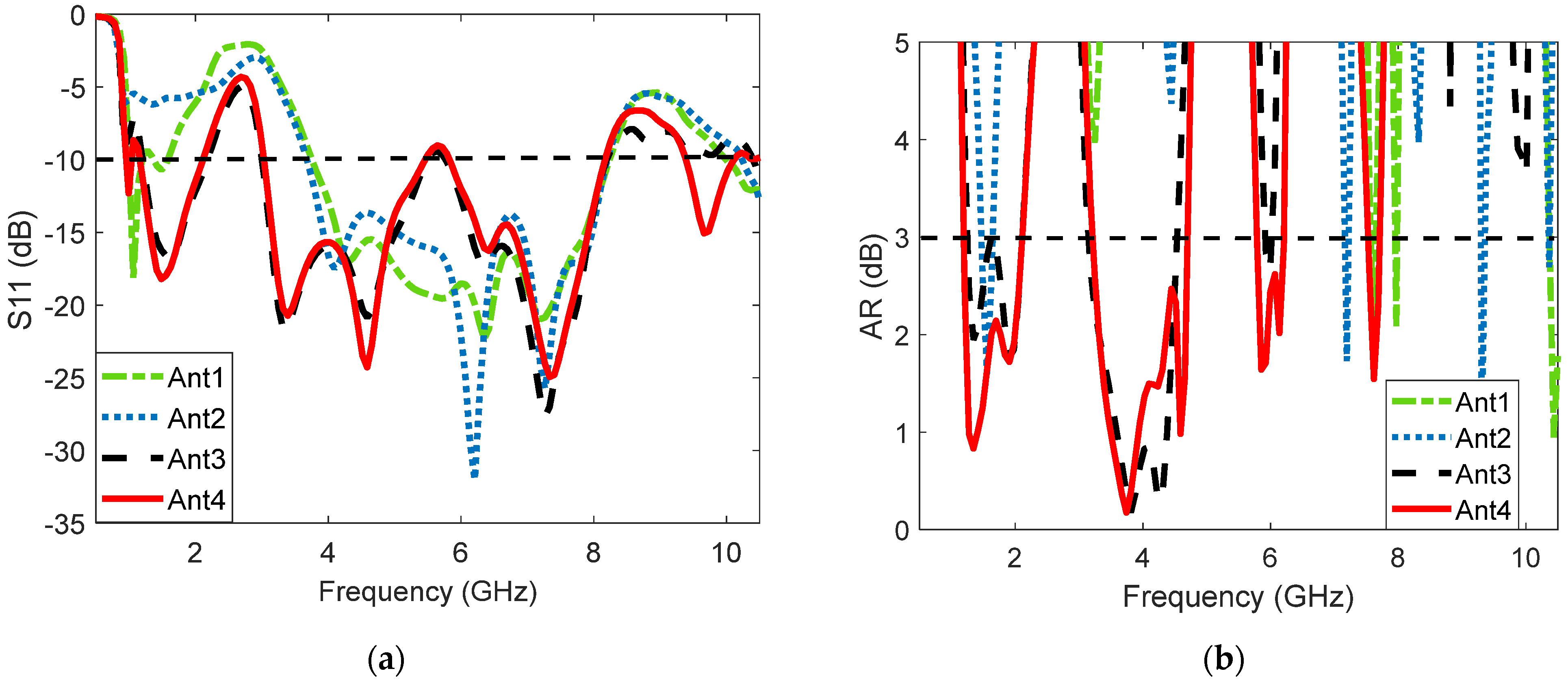
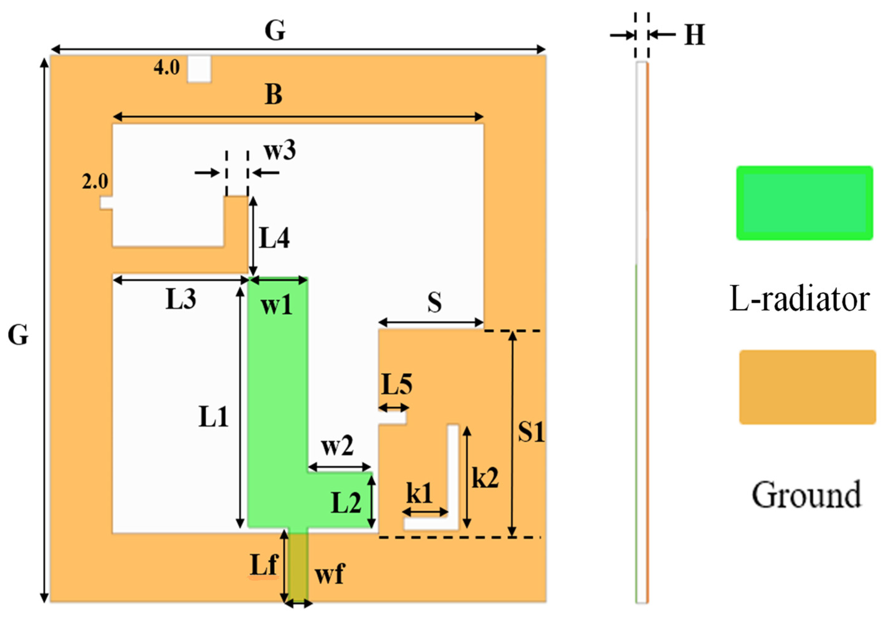
2. Structure and Analysis
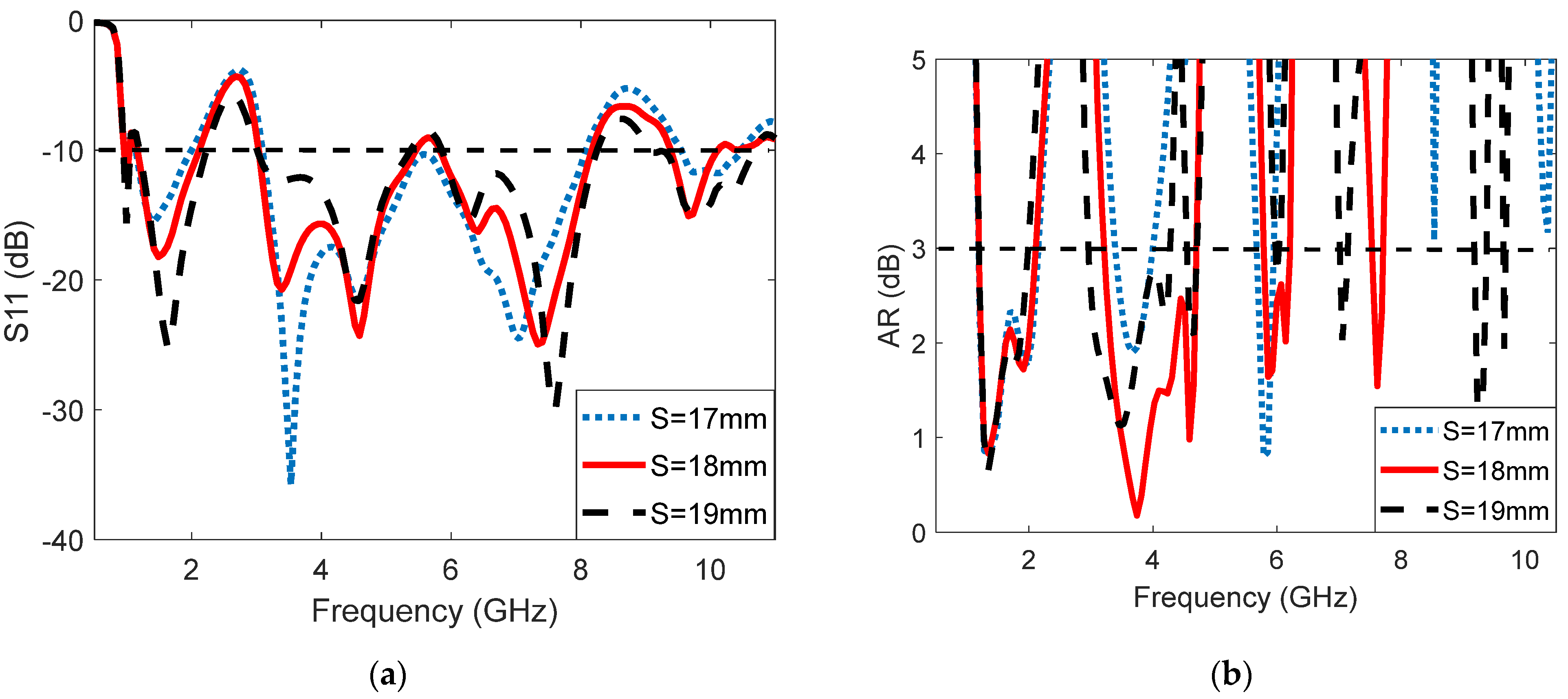
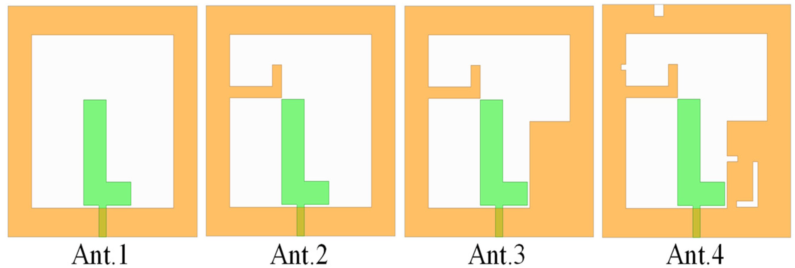
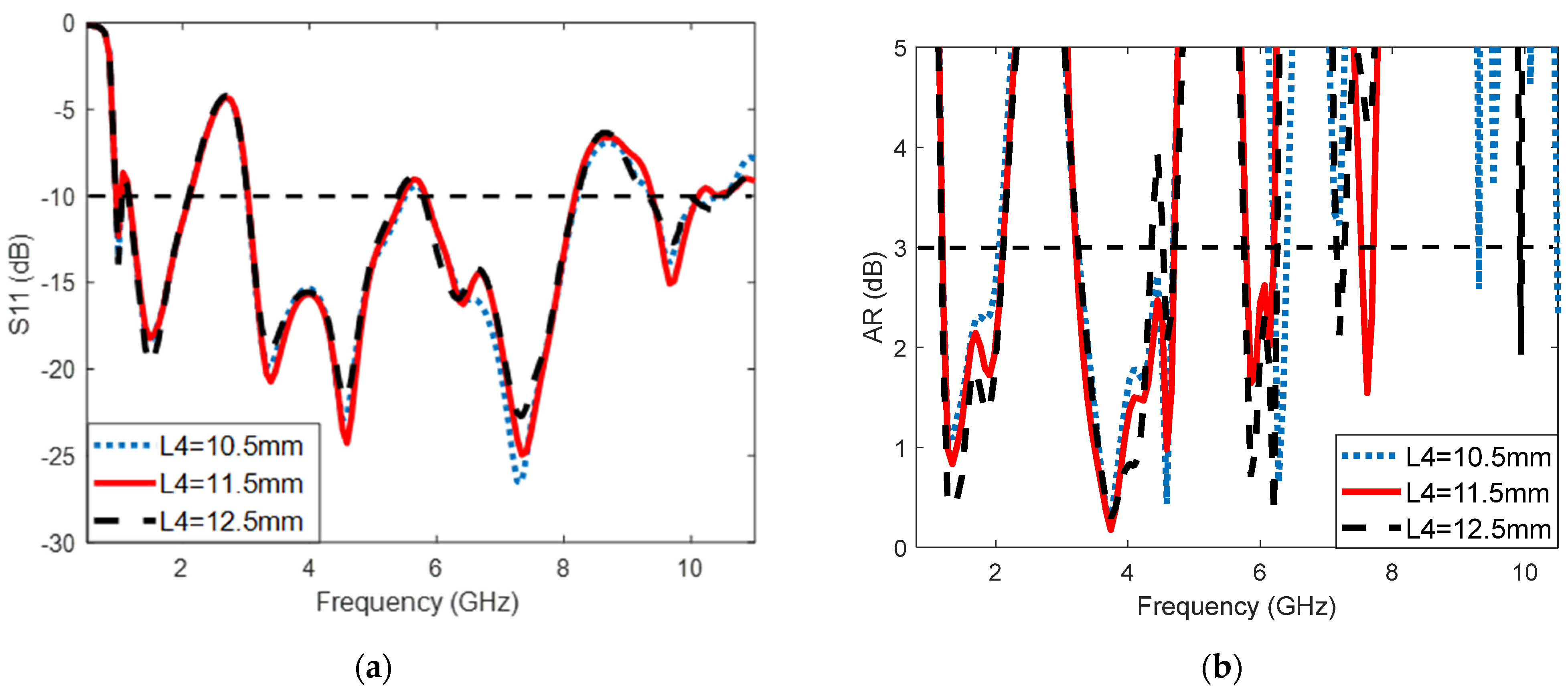
The geometry of the proposed antenna is schematically shown in Figure 1. The antenna is fed through a 50 Ω microstrip feedline. The feedline is connected to an L-shaped patch, acting as field excitation and radiator. The L-shaped patch is printed on an FR4 substrate with ε r = 4.4 and tan δ = 0.02 , and the frame ground is fabricated on the bottom of the substrate.
The side length of the substrate is G, and the thickness is H. To assess the performance of this antenna, a commercial solver, ANSYS HFSS, is used for simulation. The resultant values for each parameter are listed in Table 1.
The evolution process is illustrated in Figure 2. A square slot with side lengths of B is introduced in the ground plane, shown as Ant. 1, in Figure 2. An L-shaped stub is then protruded from the left side of the ground plane toward the center, and it is marked as Ant. 2. Following on, a rectangular patch is placed on the bottom right corner of the ground and seen as Ant. 3. At last, four slots are etched on the ground frame and shown as Ant. 4. In order to demonstrate the evolution of the antenna, the AR and impedance bandwidth of each antenna are simulated and plotted in Figure 3.
The basic structure is Ant. 1, which has a frame ground and an L-shaped radiator, as used in Ref. [30]. It is seen, from the simulated results, that Ant. 1 provides a wide impedance bandwidth in the range of 3.8–8.2 GHz. However, it is linearly polarized in this operation range. Even worse, the impedance matching is not good enough in the navigation bands. To improve the quality of circular polarization, an L-shaped branch is added to the upper left corner, as shown with Ant. 2 in Figure 2. Although the impedance bandwidth becomes worse in the low frequency around 1.5 GHz, the axial ratio is greatly improved. To create resonance in the navigation bands, a rectangular patch is placed at the lower right corner of the ground plane, as seen with Ant. 3. Apparently, the impedance bandwidth and axial ratio have been greatly improved. Therefore, the rectangular patch can improve impedance matching at lower and upper bands. By adding slots on the ground plane, the AR may be further improved, as seen with Ant. 4. The bandwidth does not see significant change, while the AR is greatly improved—particularly at 1–2 GHz and around 6 GHz.

3. Parametric Study

To examine the sensitivity of each parameter, a systematic study has been conducted. The purpose of doing this is to find the fabrication tolerance and, more importantly, to pinpoint the effects of these parameters on AR and bandwidth. We have chosen four parameters, i.e., the length of the L-shaped radiator L1, the L-shaped branch length L4, the width of the rectangular patch S, and the width of the narrow feeding line connecting to the coaxial cable. The first three parameters correspond to the evolution process, and the last parameter is chosen because it determines the input impedance, and therefore, in most cases, it is the most sensitive parameter.
The L-shaped patch acts as field excitation and a radiator. Letting L1 = 35.5, 36.5, and 37.5 mm, it is found that the reflection coefficients for these cases do not see significant variation, as shown in Figure 4. Only a slight change takes place in the 10 GHz band. For the axial ratio, the change occurs in the 7.6 GHz band. The criterium of −3 dB is not met for L1 = 37.5 mm. For the L-shaped branch, when changing the length, it is also found that the reflection coefficients do not change significantly, as shown in Figure 5. In addition, the axial ratio sees apparent change in the 4 GHz and 7.6 GHz bands. It is seen from Figure 6 that the width of the patch S does produce some effect on the reflection coefficients. However, the −10 dB bandwidths for each band do not change significantly. Its effect on the axial ratio happens in all four of the bands—particularly for the 4 GHz, 6 GHz, and 7.6 GHz bands.
The last parameter, wf, is the width of the feed. It is clearly seen from Figure 7 that the change in the width affects the reflection coefficients considerably. In other words, the impedance matching varies significantly with the change in wf. For the axial ratio, the change is much greater for the higher frequency bands than the lower frequency bands. It appears that the 4 GHz and 7.6 GHz bands are more sensitive to changes in the parameters.
It is seen, from the parametric study, that the most sensitive parameter on the impedance bandwidth is the width of the feedline wf. The width of the patch S also produces some effect on the impedance bandwidth. Other parameters have very limited effects on the impedance bandwidth. In comparison, the width of the patch S produces a considerable effect on the AR bandwidth. While the width of the feedline wf produces some effect on the AR bandwidth, other parameters have fewer effects on the AR bandwidth.

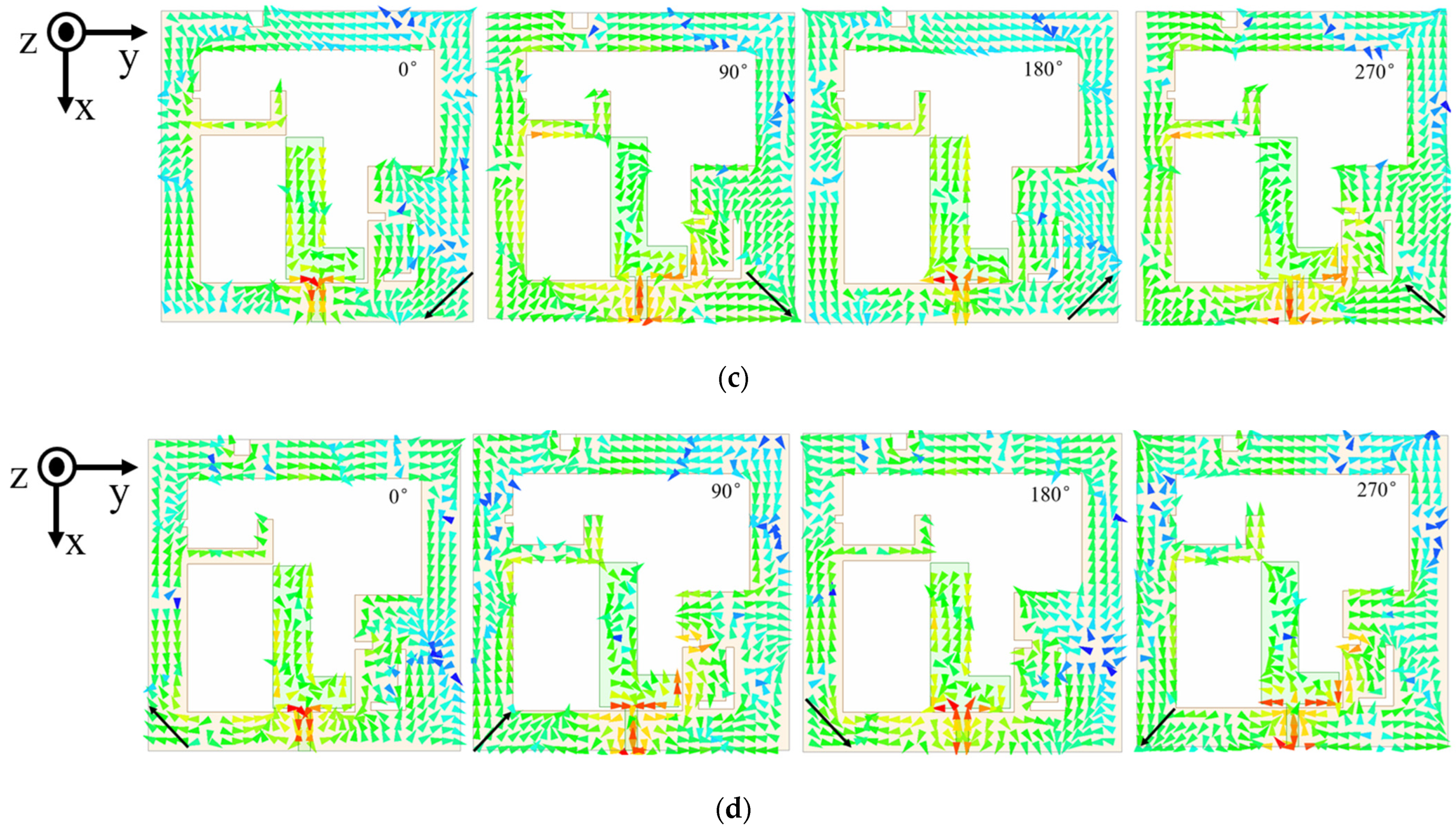
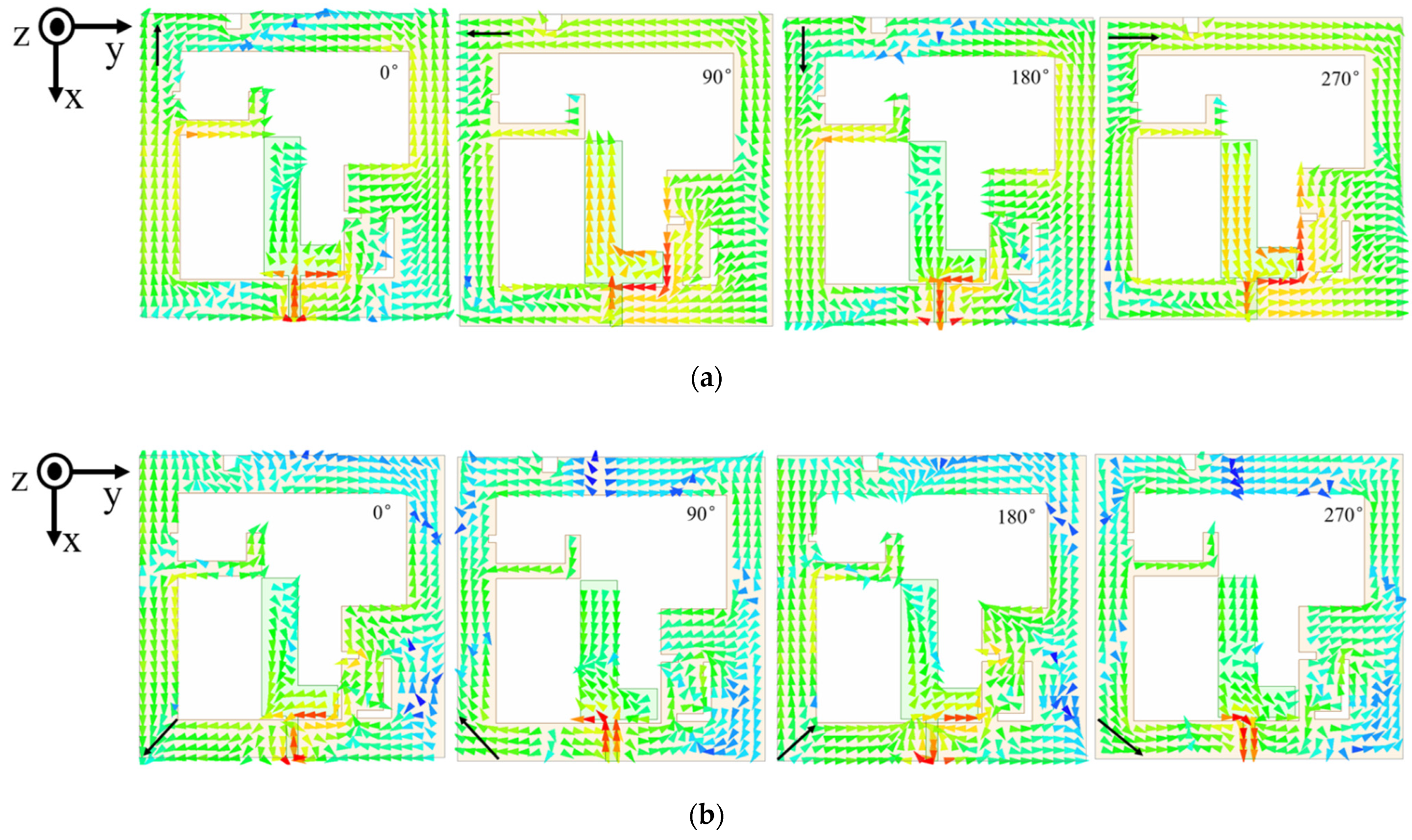
4. Currents Distribution

In order to shed more light on the process of generating circular polarization and determining the direction of the circular polarization, the surface current distributions are shown in Figure 8, where Figure 8a shows the current distributions of 0°, 90°, 180°, and 270° at 1.5 GHz. From the plot, it is seen that currents rotate, in the counterclockwise sense, as the phase increases, which means that the antenna radiates right-handed circularly polarized (RHCP) waves at low frequency bands. In addition, the current is distributed over the frame ground, indicating that the frame also functions as a radiator at 1.5 GHz. It has to be mentioned that most navigation satellite transmitting antennas are right-handed circularly polarized antennas.
The current distributions from 0° to 270°, at 4 GHz, are shown in Figure 8b. The current rotates clockwise with the increasing time phase, and the fields radiated LHCP in the +Z direction. For this frequency, however, most of the currents are located in the area of the L-shaped radiator and the patch on the left bottom corner. There are also some currents on the top part of the frame. Therefore, there are multi-resonance frequencies in this band, which is consistent with Figure 3.
Figure 8c shows the current distributions from 0° to 270° at 6 GHz. The current rotates counterclockwise with the increasing time phase, and the fields radiated RHCP in +Z direction. However, it has to be mentioned that the 6 GHz band also contains several resonances, and the bandwidth is relatively wide. Several areas contribute to the resultant polarization state. In this sense, this band is affected by several parameters, as discussed in the previous section.
The same observation can be made on the 7.6 GHz band, as seen in Figure 8d. However, the rotational sense is LHCP in the +Z direction. It is interesting to find that the rotational sense changes, alternatingly, with the frequency bands.

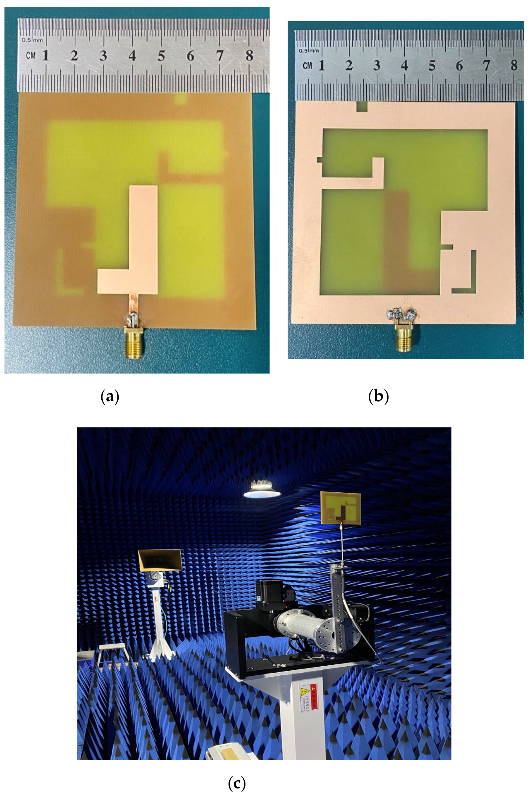
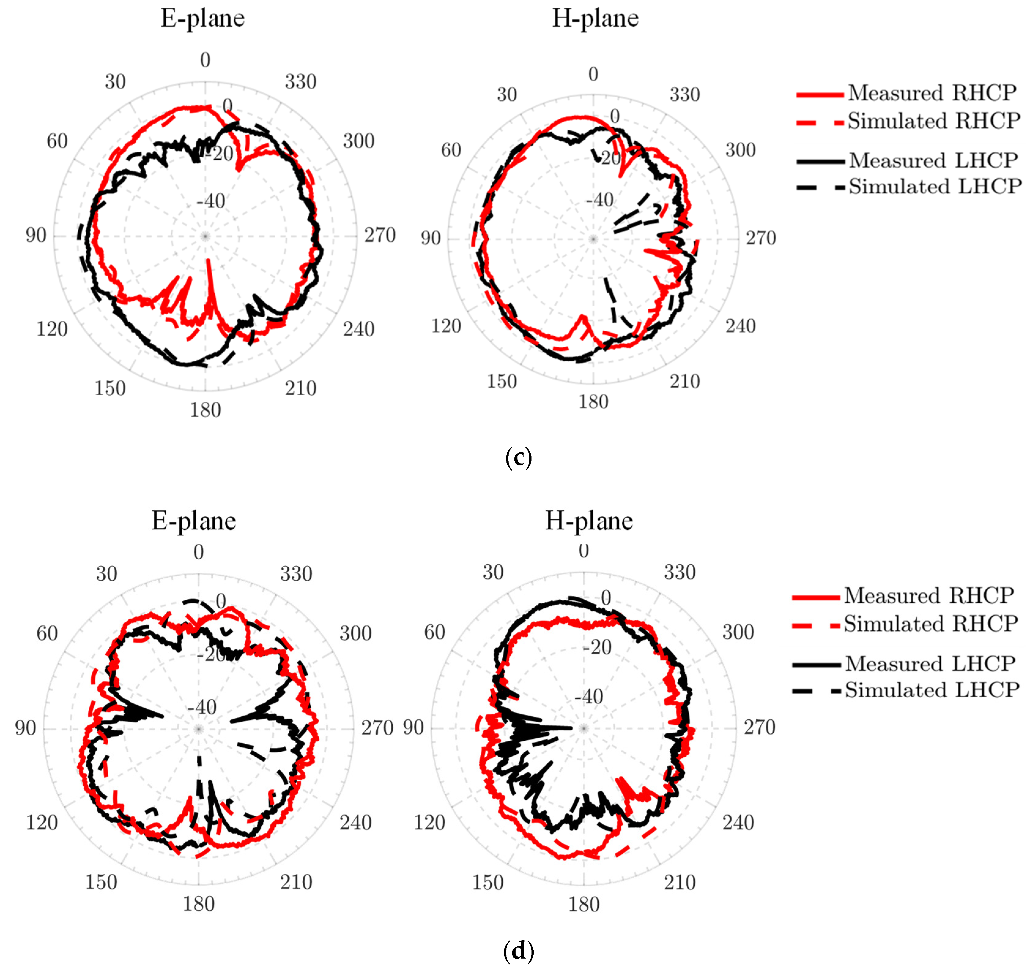
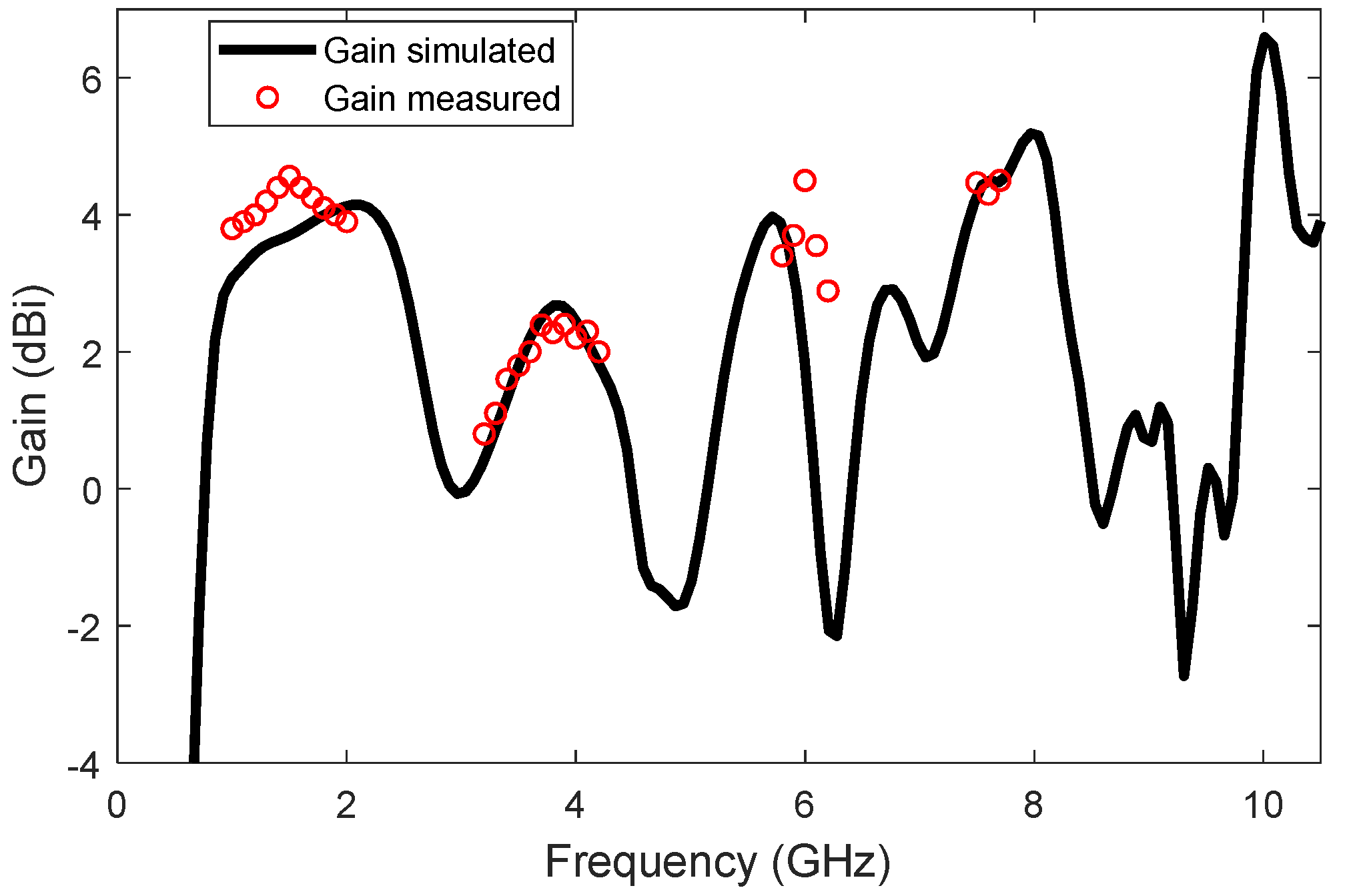
5. Measurement and Discussion

The antenna is fabricated using etching technology on an FR4 substrate. The prototype is shown in Figure 9a. The S-parameter is measured by an AV3672D vector network analyzer. The far field and gain are measured in a microwave anechoic chamber, as shown in Figure 9b. The axial ratio is retrieved from the radiation patterns.
The simulated and measured S parameters, as well as AR, are plotted in Figure 10a,b, respectively. For reflection measurement, the antenna is placed in the anechoic chamber, and the cable is connected to the VNA. Before measurement, the cable is calibrated. As can be seen from the results, four frequency bands have been successfully realized. The −10 dB bandwidths for the four bands are 75.8% (0.95–2.11 GHz), 55.8% (3.05–5.39 GHz), 39.9% (5.84–8.19 GHz), and 10.3% (9.14–10.68 GHz), respectively. The first band covers all four of the navigation systems (1.20 GHz–1.61 GHz). The second band covers several 5G bands. The third and fourth bands are for WIFI-6E and the satellite communication band.
The measured 3 dB bandwidths for AR are 59.4% (1.16–2.14 GHz), 35.8% (3.23–4.64 GHz), 8.4% (5.70–6.20 GHz), and 2.6% (7.51–7.71 GHz). The measured gains are 4.56, 2.28, 4.26, and 4.30 dBi at 1.5 GHz, 3.8 GHz, 6 GHz, and 7.6GHz, respectively. It can be observed that there is a good agreement between simulated and measured results. The slight difference is mainly due to the soldering error between the SMA connector and the feeder line. At the same time, when performing a far field test, the angle error between the turntables may also affect the test results. The measured results show that the proposed antenna can cover almost all navigation frequency bands, and it can cover 5G, N77, and N78 frequency bands at the same time.
The measured and simulated far-field radiation patterns, in E-plane and H-plane, at 1.5 GHz, 4 GHz, 6 GHz, and 7.6 GHz are plotted in Figure 11. From the radiation patterns, it is clear that the antenna can radiate RHCP at 1.5 GHz, LHCP at 4 GHz, RHCP at 6 GHz, and LHCP at 7.6 GHz in the +z direction. It can also be seen that the antenna radiates a bidirectional wave with the opposite circular polarization. The RHCP is realized in the +z direction, while LHCP is in the −z direction.
Gain measurement is conducted, by comparison, to standard-gain horn antenna. The measured gain versus the simulated gain is plotted in Figure 12. In the measurement, only the interested bands are measured. It can be seen that the measurement is in satisfactory agreement with the simulation. There are slight differences near 1.5 GHz and 6 GHz. However, the discrepancy is acceptable.
A comparison between this work and the designs in the literature is presented in Table 2. Looking at the size of the antenna, this design is moderately large. In terms of operation bands, this work provides four working bands. Particularly, the first three bands have more than 39% relative bandwidths. The first bandwidth is even greater than 75%. Regarding the axial ratio bandwidth, the first band provides a bandwidth of 59.4%, making it the widest design in Table 2. In addition, this design covers all the four navigation systems. Moreover, extra bands can be applied for 5G and WIFI-6E applications. Therefore, this design provides more communication bands with larger bandwidth over an area of moderately large.

6. Conclusions

A circularly polarized antenna with simple structure, multiple frequency bands, and a wide axial ratio bandwidth has been presented. The proposed antenna adds an L-shaped stub and a rectangular patch, on the basis of the L-shaped radiator and rectangular frame, which changes the current distribution by cutting grooves to achieve the superior performance of multiple frequency bands and the wide axial ratio bandwidth. The measured −10 dB bandwidth is 75.8% (0.95–2.11 GHz), 55.8% (3.05–5.39 GHz), 39.9% (5.84–8.19 GHz), and 10.3% (9.14–10.68 GHz), and 3-dB ARBWs are 59.4% (1.16–2.14 GHz), 35.8% (3.23–4.64 GHz), 8.4% (5.70–6.20 GHz), and 2.6% (7.51–7.71 GHz). Results show that the antenna can operate in the frequency bands from 1.16 to 2.14 GHz in RHCP for GNSS, from 3.23 to 4.64 GHz in LHCP for 5G, and from 5.925 to 7.125 GHz for WIFI-6E.

Author Contributions

Conceptualization, X.L.; methodology, H.W.; software, X.Y.; validation, J.W.; data curation, H.W.; writing—original draft preparation, H.W.; writing—review and editing, X.L.; funding acquisition, X.L., X.Y., and J.W. All authors have read and agreed to the published version of the manuscript.

Funding

This work is funded in part by the University Synergy Innovation Program of Anhui Province (GXXT-2021-027), the National Natural Science Foundation of China under the contract number of 61871003 and the open project of the state key laboratory of complex electromagnetic environment effects on electronics and information system under grant numbers of CEMEE2022Z0201B, CEMEE2021K0202A.

Conflicts of Interest

The authors declare no conflict of interest.

References

  1. Dahri, M.H.; Jamaluddin, M.H.; Khalily, M.; Abbasi, M.I.; Selvaraju, R.; Kamarudin, M.R. Polarization Diversity and Adaptive Beamsteering for 5G Reflectarrays: A Review. IEEE Access 2018, 6, 19451–19464. [Google Scholar] [CrossRef]
  2. Tubbal, F.E.; Raad, R.; Chin, K.-W. A Survey and Study of Planar Antennas for Pico-Satellites. IEEE Access 2015, 3, 2590–2612. [Google Scholar] [CrossRef] [Green Version]
  3. Chen, X.; Morton, Y.J.; Yu, W.; Truong, T.-K. GPS L1CA/BDS B1I Multipath Channel Measurements and Modeling for Dynamic Land Vehicle in Shanghai Dense Urban Area. IEEE Trans. Veh. Technol. 2020, 69, 14247–14263. [Google Scholar] [CrossRef]
  4. Zhong, Z.-P.; Zhang, X.; Liang, J.-J.; Han, C.-Z.; Fan, M.-L.; Huang, G.-L.; Xu, W.; Yuan, T. A Compact Dual-Band Circularly Polarized Antenna With Wide Axial-Ratio Beamwidth for Vehicle GPS Satellite Navigation Application. IEEE Trans. Veh. Technol. 2019, 68, 8683–8692. [Google Scholar] [CrossRef]
  5. Feng, G.; Chen, L.; Xue, X.; Shi, X. Broadband Circularly Polarized Crossed-Dipole Antenna With a Single Asymmetrical Cross-Loop. IEEE Antennas Wirel. Propag. Lett. 2017, 16, 3184–3187. [Google Scholar] [CrossRef]
  6. Liang, C.-F.; Lyu, Y.-P.; Chen, D.; Cheng, C.-H. Wideband Circularly Polarized Stacked Patch Antenna Based on TM11 and TM10. IEEE Trans. Antennas Propag. 2021. [Google Scholar] [CrossRef]
  7. Ding, K.; Gao, C.; Yu, T.; Qu, D. Broadband C-Shaped Circularly Polarized Monopole Antenna. IEEE Trans. Antennas Propag. 2015, 63, 785–790. [Google Scholar] [CrossRef]
  8. Cai, Y.-M.; Li, K.; Yin, Y.-Z.; Ren, X. Dual-Band Circularly Polarized Antenna Combining Slot and Microstrip Modes for GPS With HIS Ground Plane. IEEE Antennas Wirel. Propag. Lett. 2015, 14, 1129–1132. [Google Scholar] [CrossRef]
  9. Le, T.T.; Tran, H.H.; Park, H.C. Simple-Structured Dual-Slot Broadband Circularly Polarized Antenna. IEEE Antennas Wirel. Propag. Lett. 2018, 17, 476–479. [Google Scholar] [CrossRef]
  10. Xu, R.; Li, J.-Y.; Yang, J.-J.; Wei, K.; Qi, Y.-X. A Design of U-Shaped Slot Antenna With Broadband Dual Circularly Polarized Radiation. IEEE Trans. Antennas Propag. 2017, 65, 3217–3220. [Google Scholar] [CrossRef]
  11. Ellis, M.S.; Zhao, Z.; Wu, J.; Ding, X.; Nie, Z.; Liu, Q.-H. A Novel Simple and Compact Microstrip-Fed Circularly Polarized Wide Slot Antenna With Wide Axial Ratio Bandwidth for C-Band Applications. IEEE Trans. Antennas Propag. 2016, 64, 1552–1555. [Google Scholar] [CrossRef]
  12. Rusdiyanto, D.; Zulkifli, F.Y. Dual Band Circularly Polarized Microstrip Antenna Fed By Inverted-L Shaped With A Stub for GPS And WLAN Application. In Proceedings of the 2019 11th International Conference on Information Technology and Electrical Engineering, Pattaya, Thailand, 10–11 October 2019; IEEE: Pattaya, Thailand, 2019; pp. 1–4. [Google Scholar]
  13. Sharma, S.B.; Ugle, A.; Parikh, K. A Novel U-Slot Aperture Coupled Annular-Ring Microstrip Patch Antenna for Multiband GNSS Applications. In Proceedings of the 2020 14th European Conference on Antennas and Propagation, Copenhagen, Denmark, 15–20 March 2020; IEEE: Copenhagen, Denmark, 2020; pp. 1–3. [Google Scholar]
  14. Cao, Y.; Cheung, S.W.; Yuk, T.I. A Simple Planar Polarization Reconfigurable Monopole Antenna for GNSS/PCS. IEEE Trans. Antennas Propag. 2015, 63, 500–507. [Google Scholar] [CrossRef]
  15. Yuan, J.; Zheng, J.; Chen, Z.D. A Compact Meandered Ring Antenna Loaded With Parasitic Patches and a Slotted Ground for Global Navigation Satellite Systems. IEEE Trans. Antennas Propag. 2018, 66, 6835–6843. [Google Scholar] [CrossRef]
  16. Chen, X.; Fu, G.; Gong, S.-X.; Yan, Y.-L.; Zhao, W. Circularly Polarized Stacked Annular-Ring Microstrip Antenna With Integrated Feeding Network for UHF RFID Readers. IEEE Antennas Wirel. Propag. Lett. 2010, 9, 542–545. [Google Scholar] [CrossRef]
  17. Sun, X.; Zhang, Z.; Feng, Z. Dual-Band Circularly Polarized Stacked Annular-Ring Patch Antenna for GPS Application. IEEE Antennas Wirel. Propag. Lett. 2011, 10, 49–52. [Google Scholar] [CrossRef]
  18. Yang, H.; Fan, Y.; Liu, X. A Compact Dual-Band Stacked Patch Antenna With Dual Circular Polarizations for BeiDou Navigation Satellite Systems. IEEE Antennas Wirel. Propag. Lett. 2019, 18, 1472–1476. [Google Scholar] [CrossRef]
  19. Squadrito, P.; Livreri, P.; Di Donato, L.; Squadrito, C.; Sorbello, G. A Telemetry, Tracking, and Command Antennas System for Small-Satellite Applications. Electronics 2019, 8, 689. [Google Scholar] [CrossRef] [Green Version]
  20. Seo, D.C.; Sung, Y. Stacked Open-Loop Square Ring Antenna for Circular Polarization Operation. IEEE Antennas Wirel. Propag. Lett. 2015, 14, 835–838. [Google Scholar] [CrossRef]
  21. Yuan, J.; Chen, Z.; Chen, Z.; Li, Y. A Compact Dual-Band Microstrip Ring Antenna Using Multiring Ground for GPS L 1/ L 2-Band. IEEE Antennas Wirel. Propag. Lett. 2021, 20, 2250–2254. [Google Scholar] [CrossRef]
  22. Xu, Y.; Zhu, L.; Liu, N.-W. Design Approach for A Dual-Band Circularly Polarized Slot Antenna with Flexible Frequency Ratio and Similar In-Band Gain. IEEE Antennas Wirel. Propag. Lett. 2022. [Google Scholar] [CrossRef]
  23. Lee, S.; Yang, Y.; Lee, K.-Y.; Hwang, K.C. Dual-Band Circularly Polarized Annular Slot Antenna With a Lumped Inductor for GPS Application. IEEE Trans. Antennas Propag. 2020, 68, 8197–8202. [Google Scholar] [CrossRef]
  24. Sharma, A.; Das, G.; Gupta, S.; Gangwar, R.K. Quad-Band Quad-Sense Circularly Polarized Dielectric Resonator Antenna for GPS/CNSS/WLAN/WiMAX Applications. IEEE Antennas Wirel. Propag. Lett. 2020, 19, 403–407. [Google Scholar] [CrossRef]
  25. Ameen, M.; Thummaluru, S.R.; Chaudhary, R.K. A Compact Multilayer Triple-Band Circularly Polarized Antenna Using Anisotropic Polarization Converter. IEEE Antennas Wirel. Propag. Lett. 2021, 20, 145–149. [Google Scholar] [CrossRef]
  26. Yadav, A.; Singh, V.K.; Yadav, P.; Beliya, A.K.; Bhoi, A.K.; Barsocchi, P. Design of Circularly Polarized Triple-Band Wearable Textile Antenna with Safe Low SAR for Human Health. Electronics 2020, 9, 1366. [Google Scholar] [CrossRef]
  27. Li, J.; Shi, H.; Li, H.; Zhang, A. Quad-Band Probe-Fed Stacked Annular Patch Antenna for GNSS Applications. IEEE Antennas Wirel. Propag. Lett. 2014, 13, 372–375. [Google Scholar] [CrossRef]
  28. Li, B.; Yang, C.; Yang, Z.; Shi, J.; Li, J.; Zhang, A. Circularly Polarized Array with Enhanced Isolation Using Magnetic Metamaterials. Electronics 2019, 8, 1356. [Google Scholar] [CrossRef] [Green Version]
  29. Lai, H.W.; Wong, H. Substrate Integrated Magneto-Electric Dipole Antenna for 5G Wi-Fi. IEEE Trans. Antennas Propag. 2015, 63, 870–874. [Google Scholar] [CrossRef]
  30. Syrytsin, I.; Zhang, S.; Pedersen, G.F.; Morris, A.S. User-Shadowing Suppression for 5G Mm-Wave Mobile Terminal Antennas. IEEE Trans. Antennas Propag. 2019, 67, 4162–4172. [Google Scholar] [CrossRef] [Green Version]
  31. Xu, R.; Li, J.-Y.; Qi, Y.-X.; Yang, G.-W.; Yang, J.-J. A Design of Triple-Wideband Triple-Sense Circularly Polarized Square Slot Antenna. IEEE Antennas Wirel. Propag. Lett. 2017, 16, 1763–1766. [Google Scholar] [CrossRef]
Figure 1. Geometry and parameters of the proposed antenna.
Electronics 11 01133 g001
Figure 2. Evolution of the proposed antenna.
Electronics 11 01133 g002
Figure 3. Simulated results for Ant. 1–Ant. 4: (a) S11, (b) AR.
Electronics 11 01133 g003
Figure 4. Effect of L1 on antenna performance: (a) S11, (b) AR.
Electronics 11 01133 g004
Figure 5. Effect of L4 on antenna performance: (a) S11, (b) AR.
Electronics 11 01133 g005
Figure 6. Effect of S on antenna performance: (a) S11, (b) AR.
Electronics 11 01133 g006
Figure 7. Effect of wf on antenna performance: (a) S11, (b) AR.
Electronics 11 01133 g007
Figure 8. Surface current distributions of the proposed antenna at (a) 1.5 GHz, (b) 4 GHz, (c) 6 GHz, and (d) 7.6 GHz.
Electronics 11 01133 g008aElectronics 11 01133 g008b
Figure 9. Fabrication and measurement: (a) front view of the proposed antenna; (b) back view of the proposed antenna; (c) far field measurement in an anechoic chamber.
Electronics 11 01133 g009
Figure 10. (a) The simulated and measured S11. (b) The simulated and measured AR.
Electronics 11 01133 g010
Figure 11. The simulated and measured gain patterns, in E plane and H plane, at (a) 1.5 GHz, (b) 4 GHz, (c) 6 GHz, and (d) 7.6 GHz.
Electronics 11 01133 g011aElectronics 11 01133 g011b
Figure 12. The simulated and measured gain.
Electronics 11 01133 g012
Table 1. Dimension of the proposed antenna.
ParameterValue/mmParameterValue/mm
G80Lf11
B60W19.5
H1.6W211.5
L136.5Wf3
L28S18
L320S130
L411.5K18
L55K215.5
Table 2. Comparison of the GNSS CP antennas.
ReferencesSize (mm3)Number of BandsS11 < 10 dBAR < 3 dBApplications
[8]150 × 150 × 18212.7%, 10.1%3.3%,3.1%GPS
[9]101 × 64 × 1.52186.9%74.3%5G, WIFI-6E
[15]50 × 50 × 513.2%1.8%GPS, GLONASS
[19]47.7 × 47.7 × 5.8119.7%13.9%Telemetry tracking
and command system
[22]93.6 × 96 × 1214.75%,9.44%around 2.84GHz,5.24GHzWLAN
[23]130 × 130 × 31.52240.57%6.56%, 7.74%GPS
[24]120 × 120 × 29.6421.1%, 12.8%, 27.1%, 7.5%11.6%, 7.6%, 7.0%, 7.1%GPS, BDS, WLAN, Wi-MAX
[25]35 × 35 × 13.8313.0%, 18.2%, 14.7%3.53%, 1.73%, 13.62%Satellite application
[26]25 × 25 × 1323.4%,56.5%, 31.14%10.1%, 4.95%, 10.44%WLAN/C band
X/Ku band
[31]60 × 60 × 1.0344.0%, 70.9%35.9%, 44%, 6.3%WLAN, 5G
This work80 × 80 × 1.6475.8%, 55.8%, 39.9%, 10.3%59.4%, 35.8%, 8.4%, 2.6%GNSS, 5G, WIFI-6E
Publisher’s Note: MDPI stays neutral with regard to jurisdictional claims in published maps and institutional affiliations.

