1. Introduction
Self-driving technology for motor vehicles, such as the self-driving bus and automated guided vehicles (AGVs) in smart manufacturing, has become increasingly mature in recent years. To minimize the response times for some specific events, e.g., collisions, a detection service is deployed in AGVs. If the AGV data are saved only on the device, the management center does not know the device status or the mission progress. Therefore, managing multiple AGVs is necessary for smart manufacturing. Some AGV management systems have been proposed to guarantee safety during tasks. Monitoring the battery, for example, is the critical consideration in AGVs. AGV power comes from the batteries, and the battery management system (BMS) is important for performing tasks [
1]. If using cloud computing, the battery status information would be sent back to the cloud storage for administrators’ management. However, using a cloud BMS increases the response time because of the communication cost between the AGV and the cloud storage. On the other hand, traffic control is another issue for multiple AGVs applications. The cloud traffic controller provides centralized management to make sure that the traffic accidents do not come from the route coordination [
2]. Moving the decision maker from the device to the cloud site increases the cooperation between AGVs, but making decisions from the cloud would delay decisions. Therefore, we used a cloud service to realize centralized management, the Internet of Things [
3,
4,
5] to monitor AGVs’ status, and edge computation [
6] to minimize the communication cost for decision making. Thus, the proposed approach should be the best of both worlds by minimizing decision making delay and increasing the centralization of management.
Edge computing is used to shorten AGV response times after receiving the raw data from sensors, and an edge-based monitoring system (EMS) was developed to obtain the real-time status of each end device. If an emergency event is detected by an end device, appropriate actions are performed immediately without waiting for the data to be transmitted to a backend data center for evaluation and processing. This method can substantially shorten AGV response times. Moreover, to model unmanned vehicle deployments, Grafana was used to build an information visualization interface to rapidly deploy a visualization dashboard, enabling administrators to adjust the dashboard configuration with minimal information technology, reducing EMS maintenance costs after deployment.
Programmers can deploy customized procedures on drones to execute missions automatically. We extended the EMS from AGVs to drones to estimate the scalability of the proposed EMS. The EMS was first applied to AGVs used on a production line to remotely monitor and visualize their status during operation. However, the drone is another piece of automated guided equipment (AGE) that is used in various industries, such as agriculture [
7], disaster management [
8], and environmental monitoring and management [
9,
10]. The EMS was extended to include transportation of items using a drone. The data acquisition interface of the EMS was modified to connect to the drone’s flight control system to acquire flight information and environmental information during task execution. A comparison between the results presented in Grafana and the original log data indicated that the EMS processed data smoothly and could faithfully indicate vehicle status. Moreover, the system was easy to adjust and to apply for monitoring heterogeneous vehicles, simplifying smart manufacturing.
We propose the device monitoring framework named EMS based on edge computing. Our contributions are as follows:
Designing a framework with hybrid storage for saving heterogeneous device information.
Reducing the device’s response time by reducing unnecessary communication cost when abnormal events take place.
Providing the same system for AGVs and drones.
Dispatching missions with end devices to realize the unmanned control.
Some results related to AGVs and remote-control systems are discussed in
Section 2. The system’s development and the design of the proposed EMS framework are presented in
Section 3. The simulation results are arranged in
Section 4. The conclusion and future works are stated in
Section 5.
2. Related Works
An AGV is equipped with several batteries as its main power source. Its endurance can be increased by increasing the number of batteries, but this also increases its weight, and therefore, its power consumption. AGV task execution and the optimization of related resource allocations have been researched extensively. In recent years, novel technologies have been integrated into the power system, such as lithium batteries equipped with a BMS [
11,
12,
13], which have the advantages of smallness, high capacitance, and light weight; moreover, the battery’s status can be monitored for risk reduction during operations. Another example is lead-acid batteries, to which novel technologies have been applied for to optimize charging strategies.
In traditional service-based architecture, sensed data are transmitted to the application service layer for analysis. However, the time required for this process may cause excessive delays in generating options to immediately respond to an event. Chuixin and Hanxiang applied high speed network to AGVs to reduce the communication cost. However, the communication cost still takes place when the device data need to be sent back to the cloud storage [
14]. Lopez et al. proposed edge computing [
6], in which data processing operations are moved from the storage cloud to the device which generates the data (the "edge device"), enabling immediate processing. This idea has been applied to several applications. For example, Iván et al. considered the edge computing system in machine learning applications [
15], Muhammad et al. deployed agent level processors in each node in ad hoc networks to improve the immediacy of decision making [
16], and Guo and Nazir believe that one should consider the IoT and the computational intelligence of each process node in the library search process to decrease the response time [
17].
Edge computing studies focus on the design of edge devices, and typically emphasize optimizing devices for their intended purposes instead of developing universally applicable devices. For edge devices, additional hardware is not required for data analysis, but battery endurance must be considered. According to the results by Altaf et al., the positions of multiple drones could be traced by the flying ad hoc networks to realize the multiple controls [
18]. Thus, the device status and the control immediacy are more important in a 3D scenario than in a 2D environment.
3. System Development
The objective of this article was to build an EMS for an AGV management platform. With edge computing, AGV operating data were monitored in real-time and were used to instruct the AGV to take appropriate responsive actions [
19,
20,
21].
System Architecture
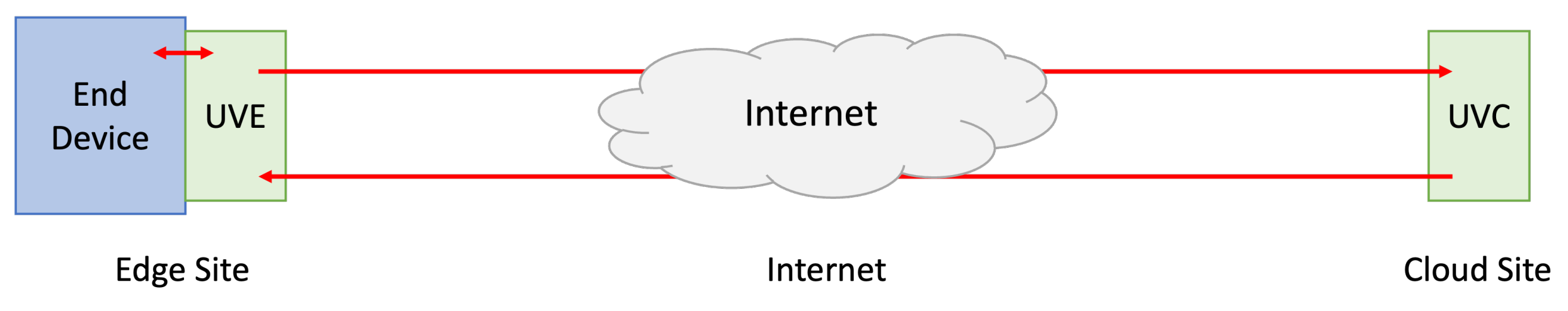
The system diagram of EMS is illustrated in
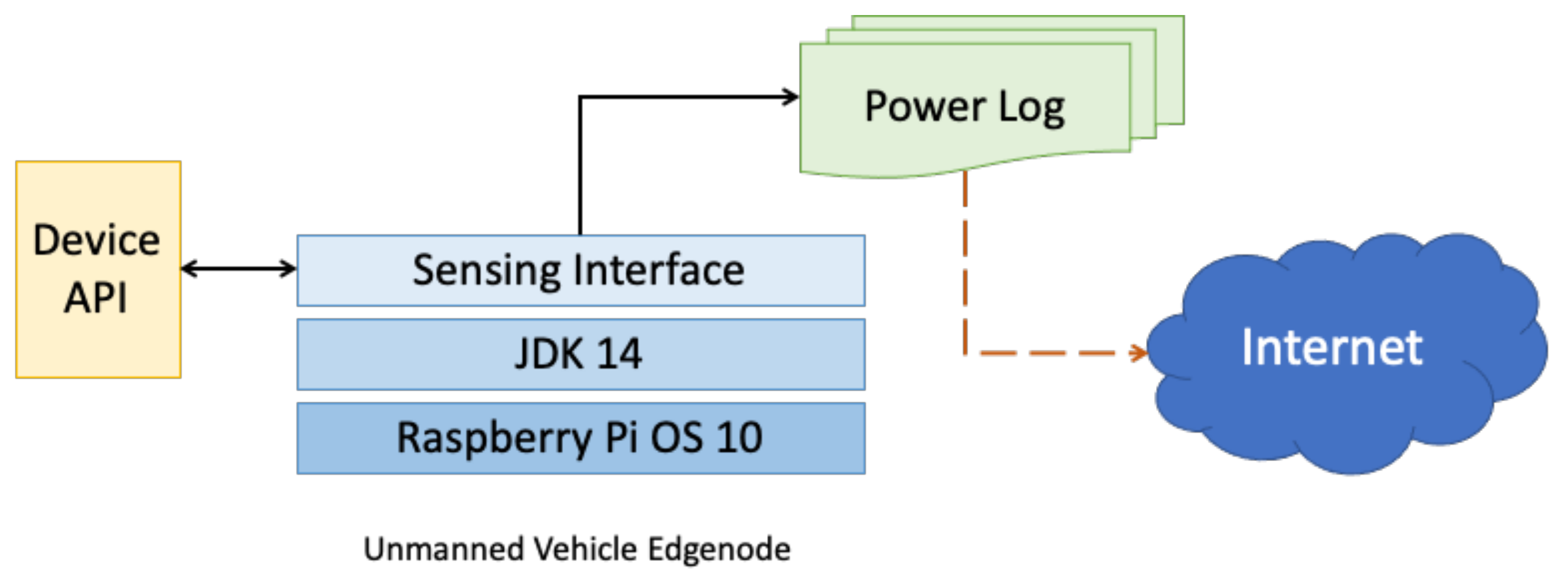
Figure 1, and the entire platform includes two parts in green: the unmanned vehicle edge node (UVE) and the unmanned vehicle controller (UVC). UVE is deployed in the end device on the left-hand-side of
Figure 2, and UVE provides the abilities of acquiring device information and sending the data back to the cloud site of EMS. Moreover, UVE could directly communicate with the end device based on the properties of the device information. On the other hand, controlling the job progress, communicating with UVE, and monitoring device status are major missions of UVC that is illustrated in the right-hand-side of
Figure 3.
As presented in
Figure 2, the edge site acquires device data regarding the AGV’s status using the device API. The sensing interface provides the ability to communicate with the end device via device API. When the device API outputs the device information, the sensing interface continuously captures the device status and organizes the information in the system’s log, and then the device log will be sent to UVC after some processes, e.g., checking the battery capacity and that the components are operating normally. The edge site was developed in Linux using Java. Java has excellent cross-platform compatibility; a compiled service can be executed by heterogeneous platforms using a Java virtual machine. Thus, the controller could dispatch services to the edge site for execution without secondary development, achieving job delivery with edge computing.
In addition to AGV data collected by the EMS, event detection and corresponding action execution services could be incorporated with a sensing interface to determine which events require immediate processing and to perform appropriate actions based on local analysis, increasing the efficiency of event responses. To avoid affecting the AGV’s power usage, the edge site was independently powered by the EMS through an external power supply.
Another component of EMS is UVC, as drawn in
Figure 3. The device information data are saved in the UVC, which is the major data process unit of the proposed EMS. A heterogeneous database is used in the EMS for the backend storage and visualizations of AGV, site, event, and status data. A MariaDB server designed for structured information was suitable for storing the data because the data have a fixed structure and are small. The sensed data regarding the AGV and its power are voluminous, whereas a single datum is small and sees substantial variation. Therefore, a relational database (RDB) may have poor access performance and was not suitable for the data storage in this application. Therefore, MongoDB, an event-driven document-oriented database, was adopted. Event-related information was saved in the JSON format, and information regarding each event was saved separately. For large numbers of events, MongoDB was more efficient than an RDB for accessing data for a single event.
Grafana was connected to the MongoDB and MariaDB servers and was used for visualization [
22,
23,
24]. As EMS administrators may not be information technology professionals, reducing the knowledge required for systems administration is key for real-world applicability. Grafana is open source; thus, only basic professional training in information technology is required for administrators to rapidly build a dedicated dashboard, enabling the simple construction of an observation interface.
4. Simulation
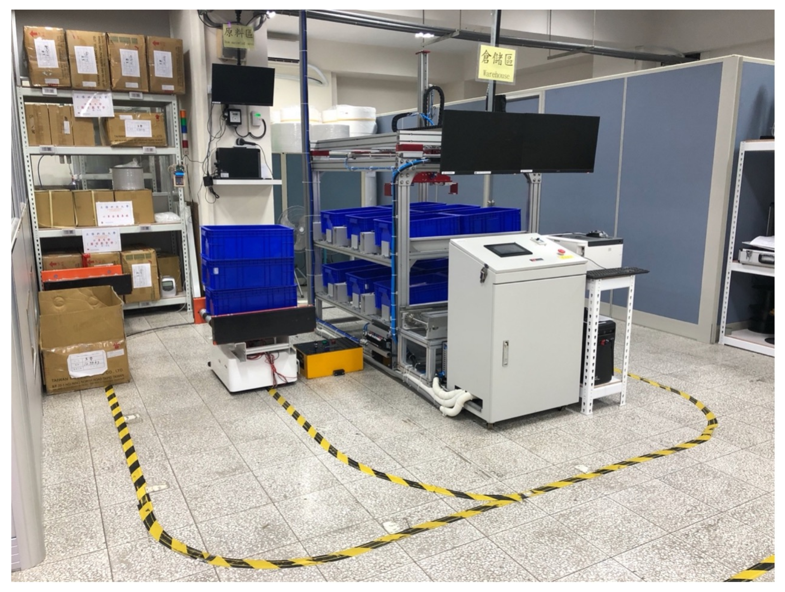
In the experiment, operational interactions between a face mask production line and line-side storage were investigated. The actual site and its route specifications are presented in
Figure 4 and
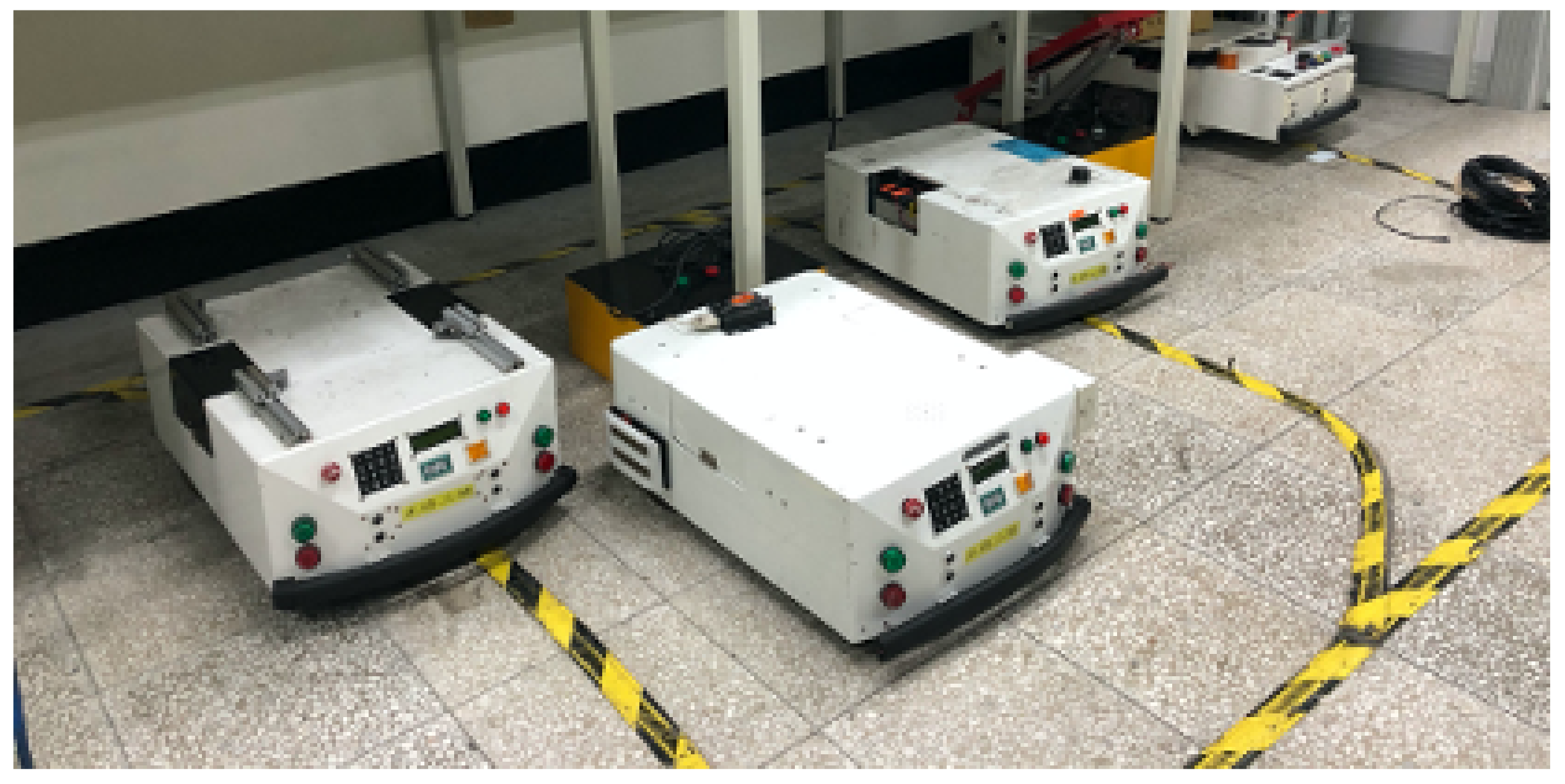
Figure 5, respectively. The AGV used to perform the practical task is presented in
Figure 6, and its specifications are listed in
Table 1. The AGV was not equipped with a BMS. The operation took approximately six to eight hours, and the operation time differed in accordance with the nature of the task.
The AGV was used to transport finished face masks from the production line to the line-side storage; it was also used to transport items for shipping. Yellow and black magnetic strips with ten RFID chips were laid on the driving routes to verify the location of the AGV.
Figure 4 shows that the product outlet of the production line was located near the paper box to the left. The products were carried on a conveyor belt and poured into the blue basket carried by the AGV. If the AGV had insufficient power, it was driven to the charging area. In
Figure 4, the yellow box on the right side of the AGV is the charging station and the working area for warehousing. Opposite to the AGV position in
Figure 4 is the warehouse’s shipping area, which is equipped with a gantry arm to place the face masks on the AGV from a designated storage location.
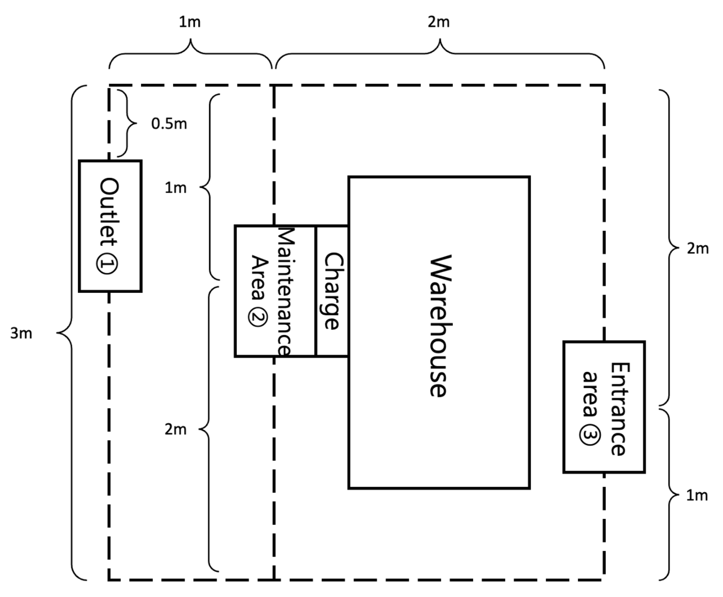
Figure 5 presents the details of the actual layout presented in
Figure 4. Two horizontal routes and three vertical routes are present when the spectator stands facing the storage control area. The site has an area of 3 m × 3 m, and the vehicle drives for 22 m to make a round trip (the outer leg and inner leg of the trip are 12 and 10 m, respectively). The AGV waits for approximately 15 min at the outlet for receiving. After receiving is completed, it stops at the warehouse entrance and waits for 2.5 min for the arm to clip the basket and place it into the storage area before placing the emptied basket back on the AGV. After these actions are completed, the AGV drives to the outlet for receiving.
4.1. Experiment Results
After the experimental apparatus was deployed, one experimenter monitored the EMS execution, and another experimenter visually verified the AGV’s motion accuracy. The primary procedures of the experimental task scenario are as follows:
Begin at the maintenance area and drive clockwise to the outlet (approximately 11.5 m).
Stop at the outlet for 15 min.
Drive from the outlet to the warehouse entrance area (5.5 m).
Wait at the warehouse entrance area for loading and unloading (approximately 2.5 min).
Drive from the warehouse entrance area to the outlet (16.5 m).
Stop at the outlet for 15 min.
Drive from the outlet to the warehouse entrance area (5.5 m).
Wait at the warehouse entrance area for loading and unloading (approximately 2.5 min).
Drive from the warehouse entrance area to the maintenance area (5 m).
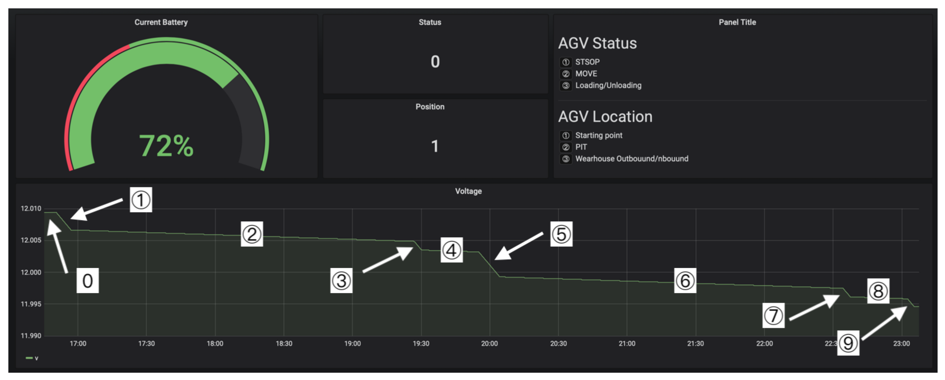
Figure 7 presents the Grafana visualization. The remaining battery power is shown at the top left corner; the low power threshold is 40%. “Status” at the top right corner indicates the AGV’s action status, and the status number is shown in “AGV Status” at the right. “Position” at the top right corner indicates the current location of “AGV Location” on the right. The line chart below presents the power consumption, the horizontal axis indicates time, and the vertical axis represents voltage.
The variation of the battery power is illustrated in the line chart below in
Figure 7. Ten points are plotted on
Figure 7 to indicate ten AGV statuses. The statuses marked from one to nine are related to the tasks listed in the above, and the data of each status are consistent with the real-world actions. The descriptions of all stages are listed as follows.
- Stage number 1
Move from the maintenance area to the outlet. This stage requires little battery for moving.
- Stage number 2
Stand by for loading objects. The AGV only requires little battery to maintain the system work.
- Stage number 3
Move from the outlet to the warehouse.
- Stage number 4
Stay in the warehouse for unloading objects. The unloading process is handled by the robotic arm that is on the top of warehouse area in
Figure 4, so AGV requires only minimum power to maintain the system.
- Stage number 5
Move from the warehouse area to the outlet.
- Stage number 6
Stay for loading objects. The power consumption in this stage is similar to that in Step 2.
- Stage number 7
Move to warehouse area that is similar to that in Step 3.
- Stage number 8
Unload objects using little battery power, which is similar to that in Step 3.
- Stage number 9
Move from the warehouse area to the maintenance area, using little battery power.
Stage zero indicates that the AGV is shutdown, so the battery power does not vary. The power variance in
Figure 7 is identical to that required by the AGV to move. The two longer, smooth segments represent the AGV is in the outlet and waits for loading objects, and two shorter sections are waiting for unloading objects in warehouse area. The results displayed with the EMS are consistent with estimates based on previous experience, indicating that the EMS could correctly report the AGV’s status.
4.2. Extended Application
The operating principle of drones is similar to that of AGVs; both use their own power to execute tasks. The drone must fly back for charging before it depletes its power reserves. If the AGV’s power is exhausted, it simply stops moving forward; the drone would fall out of the air. Therefore, the event response sensitivity required for the drone is higher than that for the AGV. The EMS was extended and used with a drone. The EMS was used to monitor the drone’s task execution status; task execution was represented with a visualization. Drones are often applied for scouting [
25,
26,
27] and shipping [
28,
29,
30]. They may also sense air data to infer the air pollution level [
31,
32]. Although they are more commonly used for scouting, the requirements for shipping are better suited to the advantages of an EMS. Therefore, goods transport using a drone was evaluated to assess extended EMS applications.
The vehicle model used in the experiment was the DJI M600 Pro; its specifications are listed in
Table 2.
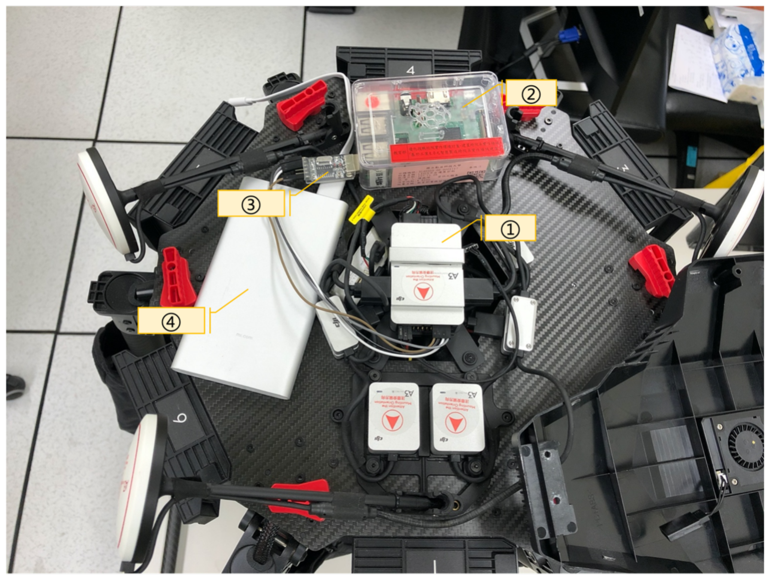
Figure 8 presents the drone with the EMS deployed. The power required for drones is much greater than that for AGVs. The flight time of drones can be extended by reducing weight; therefore, modern drones are equipped with high-capacity lithium batteries, a BMS, and an option generation system to overcome problems encountered during flight. Although drones can respond to flight events autonomously, the actions required for task execution events require additional processing. Thus, the integration of an EMS could improve the drone’s task execution. To adjust the EMS’ sensing interface for the edge site, data were acquired using the drone’s API. A Raspberry Pi was integrated in the EMS deployed in the drone and served as the edge site for the EMS (
Figure 8). As the weight of the drone affects its flight efficiency, the weight of the EMS was included in the total load weight provided to the drone for accurate computation of its services and the threshold power value for return flights.
Figure 8 presents the drone deployed with the EMS. The components relevant to EMS–drone interaction are as follows:
The flight control system (A3 PRO) of the drone.
The component of the edge site for the EMS, which can acquire A3 PRO data and external flight information.
The adapter connecting the flight control system to the EMS.
The external power supply connected to the EMS.
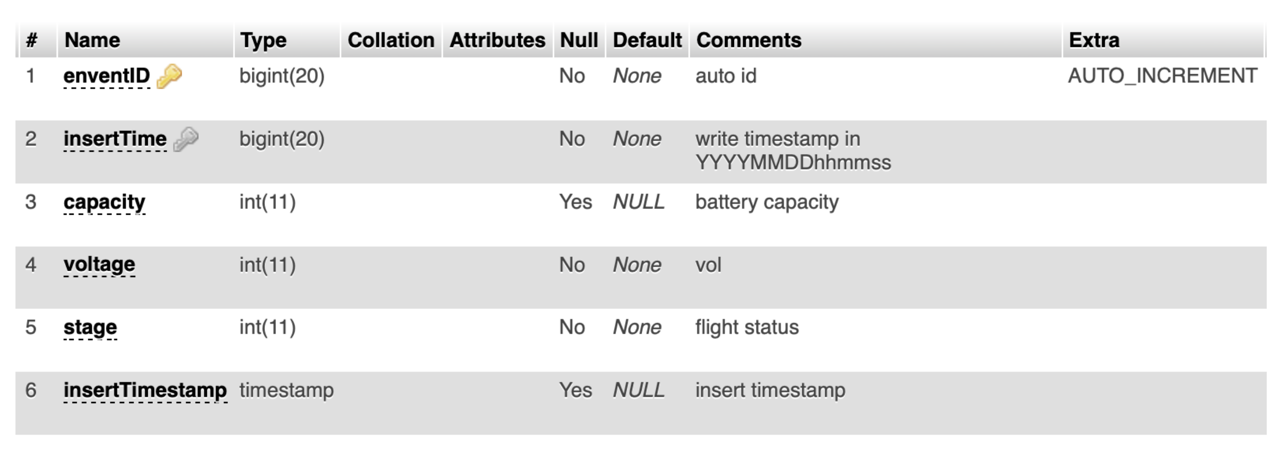
Figure 9 presents the schema used by the EMS edge site to record the flight status and data. All acquired data were first saved in this database and then examined separately to ensure data consistency. The data were included in the schedule and transmitted to the backend data storage center.
To adjust the UVE of the EMS, only the interface between the sensing interface and the device API in
Figure 2 and database field correspondence were modified. If an anomaly such as low power was detected, the EMS enabled the administrator to independently command an action, such as a return flight. The return flight action requires specific procedures, which are not as simple as those for AGVs. If the EMS activated the return flight procedures earlier than the drone did, the drone re-intervened. Conversely, if the EMS activated said procedures later than the drone, the return flight would be disrupted and re-activated. The flight events were conducted in accordance with the drone’s policies without intervention by the EMS, whereas the EMS handled task-related events while aiming to avoid interfering with the safety of the flight task.
Figure 10 presents the actual flight of the drone. The experiment was conducted in a field with an area of 160 m long by 45 m wide. Three students jointly performed the task. One student confirmed the flight status and held a remote control for human intervention should an emergency occur. Another student confirmed data collection and monitored the EMS operation. The other student visually observed the drone and made a video recording of the process.
Figure 11 presents the visualization results collected after the flight task had been accomplished. The interface was identical to that for the AGVs in
Figure 7; only the vehicle’s identification number and device status differed. Applying an EMS to monitoring drones is thus feasible by adjusting only the sensing interface. The EMS can provide greater universality if the setting values of the identification number and the status description column can be independently set as configuration profiles.
Figure 11 presents the seven stages of the drone flight from take-off to task completion and shutdown. The operation at each stage is as follows:
Turn on the vehicle and activate the system; low power consumption.
Component testing; high power consumption for testing rotor motion accuracy.
Enter standby status after completing preflight testing to receive operational commands.
Vertically move upward. This stage has the greatest power consumption (indicated by the increased slope in
Figure 11).
Move horizontally. In this stage, the drone travels the waypoint distance. With no crosswind, the power consumption is stable.
Vertically move downward. As the drone only provides sufficient lift to reduces the effects of gravity, the power consumption is lower than in the fourth and fifth stages.
Landing and system shutdown. The rotors consume no power after the flight task is completed, and battery power may rise slightly as a result.
Comparing the flight information saved by the EMS with the system log of the drone enables correct display of the drone flight status, including its power consumption and the action time in each stage; only the recorded time points of events were inconsistent. After verification, this was attributed to the inconsistent clock systems of the EMS and the drone. Therefore, the use of EMS with drones is feasible.
5. Conclusions
This study designed and developed an EMS for AGVs. EMS acquires device real-time information, and some pre-defined events could be checked directly from the acquired data. Therefore, the response time of sensing abnormal events could be reduced. EMS has been deployed on some AGVs, and the tour and job script were dispatched to the AGVs with EMS. After examining the device data acquired by EMS, the AGV motions were consistent with the EMS logs. Thus, EMS could correctly save the AGV’s status, and the process history could be reproduced by the EMS, which would be useful in the analysis of special events during tasks. Moreover, the EMS was modified to be deployed on drones, and the simulation results captured by drones were similar to those derived from the AGVs. Thus, the ability of cross-platform is another advantage of the proposed EMS.
An efficient communication framework EMS has been proposed in this study. Administrators could monitor the status of AGVs and drones during performing tasks. EMS currently provides the ability to monitor the device’s status, and the administrators could send commands to dynamically manipulate devices from the war room in the future. Therefore, WMS will provide two-way communication between administrators and end devices, and the device schedule could be more flexible and efficient.
Author Contributions
Conceptualization, C.-K.T. and F.-S.C.; methodology, C.-K.T.; software, X.-Y.L. and C.-K.T.; validation, C.-K.T. and F.-S.C.; formal analysis, C.-K.T.; investigation, X.-Y.L. and C.-K.T.; resources, X.-Y.L., C.-K.T. and F.-S.C.; data curation, X.-Y.L., C.-K.T. and F.-S.C.; writing—original draft preparation, X.-Y.L. and C.-K.T.; writing—review and editing, C.-K.T. and F.-S.C.; visualization, C.-K.T.; supervision, C.-K.T.; project administration, C.-K.T.; funding acquisition, C.-K.T. All authors have read and agreed to the published version of the manuscript.
Funding
This research was funded by Ministry of Science and Technology of the Republic of China grant number MOST 109-2221-E-167-030-MY3 and and MOST 110-2637-E-230-002-.
Conflicts of Interest
The authors declare no conflict of interest.
Abbreviations
The following abbreviations are used in this manuscript:
| AGE | Automated Guided Equipment |
| EMS | Edge-Based Monitoring System |
| UVC | Unmanned Vehicle Controller |
| UVA | Unmanned Vehicle Edge Node |
| AGV | Automated Guided Vehicle |
| BMS | Battery Management System |
| RDB | Relational Database |
References
- Shen, M.; Gao, Q. A review on battery management system from the modeling efforts to its multiapplication and integration. Int. J. Energy Res. 2019, 43, 5042–5075. [Google Scholar] [CrossRef]
- Okumuş, F.; Dönmez, E.; Kocamaz, A.F. A cloudware architecture for collaboration of multiple agvs in indoor logistics: Case study in fabric manufacturing enterprises. Electronics 2020, 9, 2023. [Google Scholar] [CrossRef]
- Yang, C.T.; Chen, H.W.; Chang, E.J.; Kristiani, E.; Nguyen, K.L.P.; Chang, J.S. Current advances and future challenges of AIoT applications in particulate matters (PM) monitoring and control. J. Hazard. Mater. 2021, 419, 126442. [Google Scholar] [CrossRef] [PubMed]
- Shen, J.H.; Chen, M.Y.; Lu, C.T.; Wang, R.H. Monitoring spatial keyword queries based on resident domains of mobile objects in IoT environments. Mob. Netw. Appl. 2020, 7, 208–218. [Google Scholar] [CrossRef]
- Shen, J.H.; Yu, C.J.; Lu, C.T.; Lin, W.; Yen, N.Y.; Huang, T.C.; Chu, H.R. Spatial air index with neighbor information for processing k-nearest neighbor searches in IoT mobile computing. J. Supercomput. 2020, 76, 6177–6194. [Google Scholar] [CrossRef]
- Garcia Lopez, P.; Montresor, A.; Epema, D.; Datta, A.; Higashino, T.; Ioana Iamnitchi, A.; Barcellos, M.; Felber, P.; Rivière, E. Edge-centric Computing: Vision and Challenges. ACM SIGCOMM Comput. Commun. Rev. 2015, 45, 37–42. [Google Scholar] [CrossRef]
- Ahirwar, S.; Swarnkar, R.; Bhukya, S.; Namwade, G. Application of drone in agriculture. Int. J. Curr. Microbiol. Appl. Sci. 2019, 8, 2500–2505. [Google Scholar] [CrossRef]
- Restas, A. Drone applications for supporting disaster management. World J. Eng. Technol. 2015, 3, 316. [Google Scholar] [CrossRef] [Green Version]
- Gallacher, D. Drone applications for environmental management in urban spaces: A review. Int. J. Sustain. Land Use Urban Plan. 2016, 3, 1–14. [Google Scholar] [CrossRef]
- Suchanek, G.; Wołoszyn, J.; Gołaś, A. Evaluation of Selected Algorithms for Air Pollution Source Localisation Using Drones. Sustainability 2022, 14, 3049. [Google Scholar] [CrossRef]
- Cheng, K.W.E.; Divakar, B.P.; Wu, H.; Ding, K.; Ho, H.F. Battery-management system (BMS) and SOC development for electrical vehicles. IEEE Trans. Veh. Technol. 2010, 60, 76–88. [Google Scholar] [CrossRef]
- Rahimi-Eichi, H.; Ojha, U.; Baronti, F.; Chow, M.Y. Battery management system: An overview of its application in the smart grid and electric vehicles. IEEE Ind. Electron. Mag. 2013, 7, 4–16. [Google Scholar] [CrossRef]
- Xiong, R.; Li, L.; Tian, J. Towards a smarter battery management system: A critical review on battery state of health monitoring methods. J. Power Sources 2018, 405, 18–29. [Google Scholar] [CrossRef]
- Chen, C.; Cheng, H. AGV Robot Based on Computer Vision and Deep Learning. In Proceedings of the 2019 3rd International Conference on Robotics and Automation Sciences (ICRAS), Wuhan, China, 1–3 June 2019; pp. 28–34. [Google Scholar]
- García-Magariño, I.; Nasralla, M.M.; Lloret, J. A Repository of Method Fragments for Agent-Oriented Development of Learning-Based Edge Computing Systems. IEEE Netw. 2021, 35, 156–162. [Google Scholar] [CrossRef]
- Khan, M.A.; Nasralla, M.M.; Umar, M.M.; Iqbal, Z.; Rehman, G.U.; Sarfraz, M.S.; Choudhury, N. A survey on the noncooperative environment in smart nodes-based Ad Hoc networks: Motivations and solutions. Secur. Commun. Netw. 2021, 2021, 9921826. [Google Scholar] [CrossRef]
- Guo, J.; Nazir, S. Internet of Things Based Intelligent Techniques in Workable Computing: An Overview. Sci. Program. 2021, 2021, 6805104. [Google Scholar] [CrossRef]
- Hussain, A.; Hussain, T.; Faisal, F.; Ali, I.; Khalil, I.; Nazir, S.; Khan, H.U. DLSA: Delay and Link Stability Aware Routing Protocol for Flying Ad-hoc Networks (FANETs). Wirel. Pers. Commun. 2021, 121, 2609–2634. [Google Scholar] [CrossRef]
- Zhang, T.; Nie, X.; Zhu, X.; Lim, E.; Ma, F.; Yu, L. Improved Camshift Algorithm in AGV Vision-based Tracking with Edge Computing. J. Supercomput.g 2022, 78, 2709–2723. [Google Scholar] [CrossRef]
- Lin, Z.; Ding, P.; Li, J. Task Scheduling and Path Planning of Multiple AGVs via Cloud and Edge Computing. In Proceedings of the 2021 IEEE International Conference on Networking, Sensing and Control (ICNSC), Xiamen, China, 3–5 December 2021; Volume 1, pp. 1–6. [Google Scholar]
- Wang, C.; Lv, Y.; Wang, Q.; Yang, D.; Zhou, G. Service-Oriented Real-Time Smart Job Shop Symmetric CPS Based on Edge Computing. Symmetry 2021, 13, 1839. [Google Scholar] [CrossRef]
- Amirudin, M.Z.; Fahmi, R.; Utami, E.; Mustafa, M.S. Evaluasi Penggunaan Prometheus dan Grafana Untuk Monitoring Database Mongodb. J. Inform. Polinema 2021, 7, 43–50. [Google Scholar]
- Cheunta, W.; Chirdchoo, N.; Chaona, S. Transformation of an Offline to an IoT-based Real-time River Water Quality Monitoring System. 2020. Available online: https://publication.npru.ac.th/jspui/handle/123456789/812 (accessed on 6 March 2022).
- González, I.; Portalo, J.M.; Calderón, A.J. Configurable IoT Open-Source Hardware and Software IV Curve Tracer for Photovoltaic Generators. Sensors 2021, 21, 7650. [Google Scholar] [CrossRef] [PubMed]
- Adão, T.; Hruška, J.; Pádua, L.; Bessa, J.; Peres, E.; Morais, R.; Sousa, J.J. Hyperspectral imaging: A review on UAV-based sensors, data processing and applications for agriculture and forestry. Remote Sens. 2017, 9, 1110. [Google Scholar] [CrossRef] [Green Version]
- Comba, L.; Biglia, A.; Aimonino, D.R.; Gay, P. Unsupervised detection of vineyards by 3D point-cloud UAV photogrammetry for precision agriculture. Comput. Electron. Agric. 2018, 155, 84–95. [Google Scholar] [CrossRef]
- Tsouros, D.C.; Bibi, S.; Sarigiannidis, P.G. A review on UAV-based applications for precision agriculture. Information 2019, 10, 349. [Google Scholar] [CrossRef] [Green Version]
- Sopper, C.; Woodworth, A. Inflatable Packaging for Use with UAV. U.S. Patent No. 10,131,428, 20 November 2018. [Google Scholar]
- Jung, S.; Kim, H. Analysis of amazon prime air uav delivery service. J. Knowl. Inf. Technol. Syst. 2017, 12, 253–266. [Google Scholar]
- Abdullah, A.; Jaafar, J.; Tahar, K.N.; Razali, M.H. Shipping Container Counting Approach Using Unmanned Aerial Vehicle (UAV) and ArcGIS. Built Environ. 2019, 16, 15–26. [Google Scholar] [CrossRef]
- Kristiani, E.; Chen, Y.A.; Yang, C.T.; Huang, C.Y.; Tsan, Y.T.; Chan, W.C. Using deep ensemble for influenza-like illness consultation rate prediction. Future Gener. Comput. Syst. 2021, 117, 369–386. [Google Scholar] [CrossRef]
- Kristiani, E.; Yang, C.T.; Huang, C.Y.; Ko, P.C.; Fathoni, H. On construction of sensors, edge, and cloud (ISEC) framework for smart system integration and applications. IEEE Internet Things J. 2020, 8, 309–319. [Google Scholar] [CrossRef]
| Publisher’s Note: MDPI stays neutral with regard to jurisdictional claims in published maps and institutional affiliations. |
© 2022 by the authors. Licensee MDPI, Basel, Switzerland. This article is an open access article distributed under the terms and conditions of the Creative Commons Attribution (CC BY) license (https://creativecommons.org/licenses/by/4.0/).


