Article

Volatile Memristor in Leaky Integrate-and-Fire Neurons: Circuit Simulation and Experimental Study

Faculty of Technical Sciences, University of Novi Sad, 21000 Novi Sad, Serbia
*
Author to whom correspondence should be addressed.
Electronics 2022, 11(6), 894; https://doi.org/10.3390/electronics11060894
Submission received: 31 December 2021 / Revised: 2 February 2022 / Accepted: 11 February 2022 / Published: 13 March 2022
(This article belongs to the Section Circuit and Signal Processing)

Abstract

:
In this paper, circuit implementation of a leaky integrate-and-fire neuron model with a volatile memristor was proposed and simulated in the SPICE simulation environment. We demonstrate that simple leaky integrate-and-fire (LIF) neuron models composed of: volatile memristor, membrane capacitance and neuron resistance can mimic spatial and temporal integration, firing function and signal decay. The existing leaky term originates from the recovery of the initial resistive state in the memristor in the spontaneous reset cycle, which is essential for emulating the forgetting process in all-memristive neural networks (MNNs). Furthermore, a diffusive perovskite memristor was used to validate the model where intrinsic memristors’ capacitance acts as neuron membrane capacitance. Good agreement with experimental and simulation results was observed. Volatility, as an inherent property of specific memristors, eliminates the need for usage of an additional peripheral circuit which will reinitialize device state, thus allowing the development of energy-efficient, large scale complex memristive neural networks. The presented circuit level model of LIF neurons can facilitate the design of MNNs.

1. Introduction

The application of memristors as part of artificial neural networks (ANN), especially spiking neural networks (SNN) has been extensively studied in recent years [1,2,3,4] due to their unique performances such as: adjustable conductance, multilevel resistance states, fast operation speed, low dissipation, and prominent scaling potential [2,5]. Memristive synapse, for instance, allows implementation of Spike Time Dependent Plasticity (STDP) learning rule [6] as a result of existing ability to memorize state and process information. Furthermore, memristors can be implemented in neural networks in the form of various memristive synapse circuits: single memristor (1M), two memristors (2M), one memristor-one transistor (1M-1T), four memristor synapse circuit (4M), etc. [1,2]. Nowadays, various memristive neuron models are available in the literature: Hodgkin–Huxley [7], FitzHugh–Nagumo [8], Hindmarsh–Rose [9], integrate-and-fire model [6], and leaky integrate-and-fire model [10]. Although the well-known Hodgkin–Huxley model [11] presents the most accurate biologically plausible neuron model, the memristive interpretation of this model requires the existence of rare local-activity behaviour reported only in a few physically realized devices [12,13].
On the other hand, the leaky integrate-and-fire model (LIF), is the most commonly used neuron model in spiking neural networks, [4,14], due to its simple realization, with the ability to perform the following essential neuron functionalities: signal integration, firing function and decay of local gradient potential (LGP). Memristive LIF neurons may require additional peripheral circuits: Schmitt trigger-based amplifier-STBA [15], comparator, and pulse generator [16] depending on the properties of memristor itself, which should discharge the capacitor, the element that mimics neural membrane capacitance, and reset the memristor state.
Recently, an all-memristive neural network was presented with a simple memristive LIF neuron circuit and additional membrane capacitance and axon resistance, where leaky functionality was realized using volatility in diffusive memristor, while drift memristor was used in a synaptic circuit composed of one memristor and one transistor (1M-1T) [17].
Although the volatile characteristics of memristors’ response were considered originally as unwanted, they have become more interesting recently due to the valuable feature, specifically useful in advanced neuromorphic architectures [17,18,19], selectors [20], in security applications as random generators [21], etc. Volatile memristors can be included either as part of a neuron cell circuit of a memristive neural network [17] or in combination with a non-volatile drift memristor for emulation of synaptic activity [18].
Aiming to standardize the characterization techniques, novel experimental protocols have been proposed recently [22], revealing some of the following effects: number of programming pulses, programming amplitude, polarity, overall input energy on resistive RAM (ReRAM) relaxation response. Available literature reports on the existence of both metastable-volatile and stable-non-volatile states within the same memristive device, dependent on the electrical potential gradient and device history [22,23].
Furthermore, a modelling methodology that accounts for bidirectional volatility was presented in [24], predicting a transient change of memristance through the data-driven analytical approach. In a recent study [25], physical models of the filamentary type of volatile resistive switching devices were presented accounting for Ag nanoparticles motion, which defines disruption and formation of the filament. This model is numerical and based on Monte Carlo simulations and molecular dynamics, whereas the same group of authors presented the analytical model [26], also for volatile memristors confirmed through measurement of ac characteristics and filament disruption dynamics. Application of this physical-based model as ReRAM synapse is demonstrated consisting of a single volatile and non-volatile memristor, mimicking short-term memory effect. Other physical models of volatile/diffusive memristors are also available and based on: electrical, mechanical, thermal effects and electrochemical reaction on filament dynamics [17,18].
Starting from the circuit-level SPICE model, which incorporates both non-volatile and volatile effects in memristor [23], in this paper we included our new window function [27,28] in the memristor’s model. The memristor’s model was then used in the SPICE simulation of a simple LIF artificial neuron circuit for all-memristive neural networks. Numerical results show that the model can mimic spatial-temporal integration, firing function and leaky functionality of a biological neuron. Results of conducted simulations were verified through carried out experiment on perovskite Pt/BaTiO3/Pt diffusive thin film memristor due to the fact that perovskite materials have already proven as good candidates for an active material in diffusive memristors [16]. For the realization of the LIF circuit, internal capacitance of memristor was used to mimic membrane capacitance in a biological neuron and shunt resistor was used as neuron resistance. A good agreement between numerical and experimental findings was observed. As far as our knowledge, this is the first circuit-based SPICE model of simple LIF neuron with volatile memristor which can be used in all-memristive neural networks. Validation of the proposed model was performed by comparison of simulated and experimental results obtained as a response of perovskite volatile memristor in the LIF neuron circuit. This circuit model of LIF neuron allows decoupling of memristive and capacitive influence of neuron response, without the usage of additional optimization tools, such as genetic algorithm [15], and can be potentially used for simulation of complex large memristive neural networks.

2. Materials and Methods

Simulations of volatile memristor and leaky integrate-and-fire artificial neuron circuits were performed in the SPICE simulating environment (LTspice version). Pt/BaTiO3/Pt (BTO) diffusive/volatile memristors were fabricated by spin-coating deposition technique of stable precursor solutions [29], on silicon substrate coated with platinum Pt(~150 nm)/TiO2(~40 nm)/SiO2(500 nm) (Vin Karola Instruments, Norcross, GA, USA). Top Pt electrode (~100 nm) was deposited by sputtering (LeyboldHeraeusL560Q) on BTO (~100 nm) film. The dynamical response of the LIF circuit was experimentally studied with a measurement setup consisting of NI USB 6351 data acquisition card (National instruments, Austin, TX, USA) and SDG1025 arbitrary waveform generator (Siglent Technologies). SDG1025 is used to supply predefined waveforms to the LIF circuit, while NI USB 6351 is used for the measurement of memristor current and voltage. Memristor current was calculated based on the voltage drop measured across the series resistor (resistor is utilized as a shunt or current sensing resistor). The LabVIEW virtual instrument is designed for simultaneous control of the waveform generator and data acquisition card. Timing characteristic and relaxation time were estimated using Keithley 2410 High-Voltage Source Meter (Tektronix) also controlled with LabVIEW, while frequency analysis of capacitance was performed using Hioki IM3590 impedance analysed (HiokiE.E. Corporation, Nagano, Japan) in frequency range from 1 Hz–100 Hz using the equivalent circuit of parallel connection between capacitor and resistor. Electrical measurements were performed at room temperature in laboratory conditions.

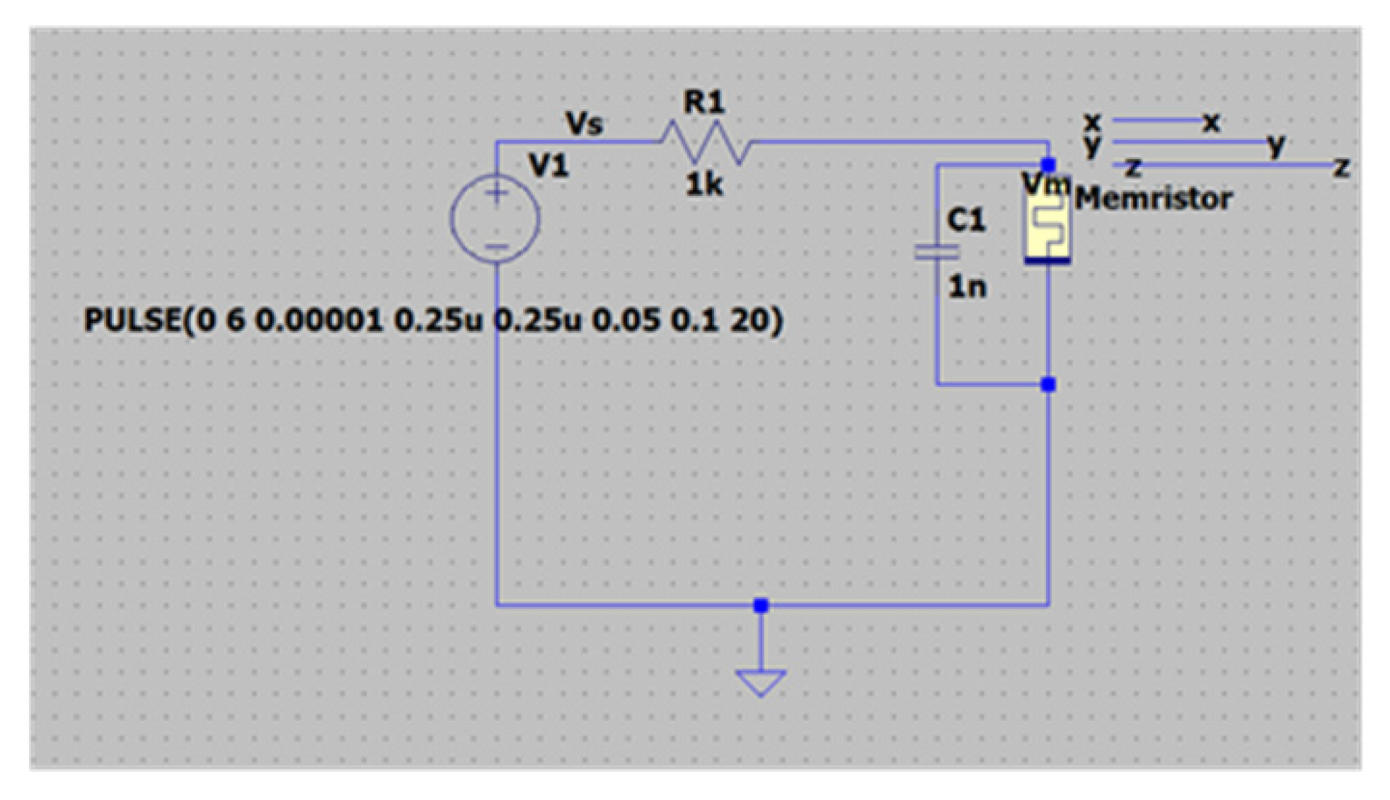
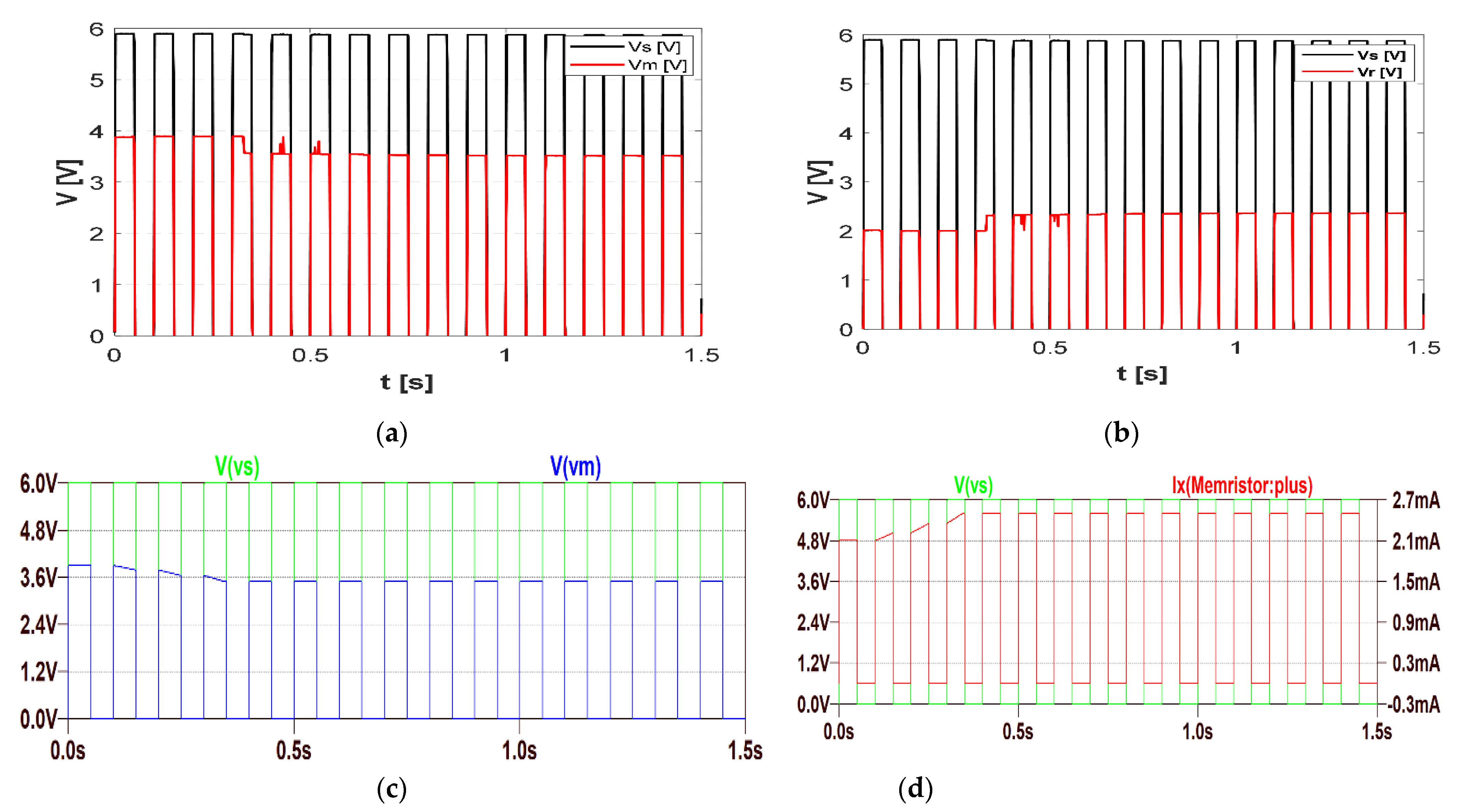
3. Simulation of LIF Neuron with Volatile Memristor

Starting from the reported SPICE model which can incorporate memristor volatility [23], we included our new window function
f N ( x ) = 1 ( 2 x 1 ) 2 1 ( 2 x 1 ) 2 + ( 2 x 1 ) 2 N   ,
where parameter N corresponds to parameter p of original Joglekar [30] and Prodromakis [31] window functions. The properties of novel window functions compared to other window functions most often used in literature are listed in Table 1.
In addition to the properties listed in Table 1, the novel window function f N ( x ) has the first 2 N 1 consecutive derivatives equal to zero at x = 1 / 2 . Since f N ( 1 / 2 ) = 1 and f N ( x ) 1 , it follows that f N ( x ) has flattened maximum at x = 1 / 2 . The function f N ( x ) is shown in Figure 1a for N = 1 ~ 10 . Based on the results from [27], the specific advantage of the proposed novel window function is the possibility to determine exact closed-form analytical solutions, expressing the dependence of the charge q (flux φ) on the state variable x, in the case of the used model of memristor:
q ( x ) = 1 4 k [ ln x 1 x 2 n = 1 N 1 ( 2 x 1 ) 2 n + 1 2 n + 1 ] ,
φ ( x ) = 1 4 k [ R o f f ln ( 2 x ) R o n ln ( 2 2 x ) + R o f f n = 3 2 N ( 1 2 x ) n n R o n n = 3 2 N ( 2 x 1 ) n n ] .
In this way, when our model is used in numerical simulations, we do not have to numerically solve the state equation d x / d t = k f ( x ) i . Instead, for current-controlled (voltage-controlled) memristor, from i ( t ) ( u ( t ) ) we obtain q ( t )   ( φ ( t ) ) , and for each value of the charge q (flux φ) we can numerically solve nonlinear algebraic equation q ( x ) ( φ ( x ) ) by x, and substitute this x in the state-dependent Ohm’s law of memristor v M ( t ) = R M ( x ) i M ( t )   ( i M ( t ) = G M ( x ) v M ( t ) ) . With respect to the monotonicity of the functions q ( x ) and φ ( x ) , there exists only one solution x ( 0 , 1 ) in both cases. The influence of the window function on current–voltage characteristics is presented in Figure 1b.
The model of the volatile memristor is composed of four cells: terminal cell, x-module, y-module and z-module, which realize coupled differential equations [23]. Terminal cell of the model as originally proposed by Biolek [32], brings the well-known current –voltage relation of memristors:
v M ( t ) = R M ( x ) i M ( t ) ,
where v M ( t ) and i M ( t ) represent memristor voltage and current, respectively. Resistance R M ( x ) depends on state variable x and values of High Resistance State, HRS, R O F F and Low Resistance State R O N :
R M ( x ) = R O N x + R O F F ( 1 x )
Additional module cells: x, y and z are composed of controlled current and voltage sources, used to implement coupling between differential equations, resistors and capacitors ( R x , C x ,   C y ,   R z ,   C z ), which determine the rate of volatile and non-volatile switching, time constant and leaky function. For more details see [23]. It is important to note that parameters of module cell x, y and z as well as the cell circuit itself, do not have physical interpretation and are only used to implement corresponding differential equations [23,35]. In this paper, we modified the equation for the current of controlled sources using a new window function f N ( x ) , therefore obtaining the following form for the x-cell controlled current source:
I C ( x ) = i M μ V R O N D 2 1 ( 2 x 1 ) 2 1 ( 2 x 1 ) 2 + ( 2 x 1 ) 2 N   ,
where μ V stands for dopant mobility, and D represents the thickness of the active layer. The controlled current source in y-cell is obtained by analogy.
As recently demonstrated, volatile memristors are suitable candidates for realizing Leaky integrate-and-fire artificial neuron circuit [16,17], as besides integration they could implement the “leaky” function of biological neurons after the actuation signal (input stimulus) is turned off. Here, we incorporated the volatile memristor SPICE model of a memristive artificial neuron, proposed in the recent paper presenting neurons in an all-memristive neural network [17]. The LIF neuron circuit, see Figure 2, is composed of neuron resistance R, neuron capacitance C and memristor M. Voltage source, VS, as stimulus generator, generates input signals (pulses) on voltage divider circuit formed of a neuron resistance and parallelly connected memristor and capacitor. Memristor models the variable ion channel conductivity, while the capacitor is used to implement cell membrane capacitance [17]. For a large on-to-off resistance ratio of memristor, a capacitor is charged through input resistance R, and the capacitor voltage value is increased. Eventually, capacitor voltage reaches the memristors threshold voltage value, switching it to LRS (on-state), which presents the onset of a capacitor discharging through the memristor. Abrupt changes of memristance are detected as the “firing” event in the artificial neuron. After the pulse train voltage is turned off, the volatile memristor turns to HRS (off-state), which eliminates the need for additional reset circuits.
Results of the SPICE simulations of LIF neuron with volatile memristor are given in Figure 3, parameters values were implemented from [23], while external components equal to: neuron resistance is R = 10 Ωk and membrane capacitance is initially set to C = 50 nF and later variated demonstrating their influence on neuron dynamics. SPICE code (LTspice version) used for simulation of the volatile memristor is included in Appendix A. Values of memristor’s subcircuit model parameters are given in Table 2, while independent and controlled source values follow from the model’s equation [23].
The neuron circuit is stimulated with multiple subsequent voltage pulses of the following characteristics: pulse duration 1 ms, pulse period 2 ms and amplitude 0.5·V (subthreshold value). Results, given in Figure 3 are shown for two pulse trains with five consecutive pulses and a resting period of 180 ms. Firing occurs at the t f ~ 5   ms detected as memristor’s current increase, Figure 3 (middle graph, Ix-memristor current in referent direction) and discharging of the capacitor (bottom graph), i.e., decay of voltage across parallel circuit formed from memristor and capacitor ( v M ). This behaviour is classified as memristors’ threshold switching initiated by the pulse input stimulus, where the required time to reach the threshold corresponds to integration time in neuron dynamics [17]. Resting period t r between the pulses is chosen to demonstrate the volatility effect in the LIF neuron circuit. Namely, following the increase rate of memristance R M after the switching, Figure 3 (top graph), turns back to the initial resistive state value during the resting period t r , simulating decay of local graded potential (LGP), i.e., “leaky” or forgetting function in the biological neuron. This initial value of memristance is a biological counterpart to the resting state of LGP. Relaxation or decay time allows the implementation of STM in artificial neural networks [17]. Following, second pulse train in the simulations, starting from t r , induces same effect: charging of membrane capacitance, and transition of memristor’s state.
It is worth noticing that memristance transient response highly depends on input stimulus energy, device history, switching threshold values [22] and on-to-off ratio. Respectively, volatile phenomenon, yet not entirely revealed can be considered as spontaneous reset process and returning the device in an initial state.
It is known in the literature [16], that the spatial integration function of an artificial neuron can be validated as a circuit response under external stimulation with different amplitudes, presenting summed spatial stimulus signals. Namely, biological action potential has uniform amplitude, thus the sum of multiple input signals arriving at the same cell can be modelled with the alteration of signal amplitudes. LIF model of a neuron implemented in SPICE environment can also demonstrate spatial integration functionality, e.g., after increasing amplitude of pulse train input signals from 0.5 V to 1 V (see Figure 4a), a rise of spike current is observed, from ~90 µA (Figure 3) to ~320 µA (Figure 4a), respectively. For larger stimulus amplitude, firing event occurs faster as fewer pulses are required for memristor to reach the threshold value.
The temporal integration function of a biological neuron allows summation of signals with different frequencies, which will consequently generate a different spike response [16]. This process is also possible to emulate using the proposed LIF model in the SPICE environment, as higher values of input frequencies induce larger response current, i.e., increased stimulus frequency from 500 Hz to 2 kHz, see Figure 4b,c for comparison, induces 60% current response increase. This behaviour is recognized as temporal signal high pass filtering and originates from diffusion processes in volatile memristor, as dynamical modulation of memristance [16].
Neuron resistance and membrane capacitance values also have an immense impact on firing dynamics [17], which could be observable using the proposed SPICE model.
Starting from membrane capacitance, larger values result in extra pulses required to generate the spike, see Figure 4a,b for comparison for the same stimulus signal due to higher time constant of capacitance charging. Spike current is increased due to the larger amount of stored charge in the capacitor. On the other hand, neuron resistance value in the model influences on the time constant of the capacitor charging (required time to turn on the memristor), i.e., spike time occurrence (integration time) and spike amplitude (Figure 4b vs. Figure 4d). Neuron resistance can be used to model synaptic weight, larger values correspond to lower weight and vice versa [17].

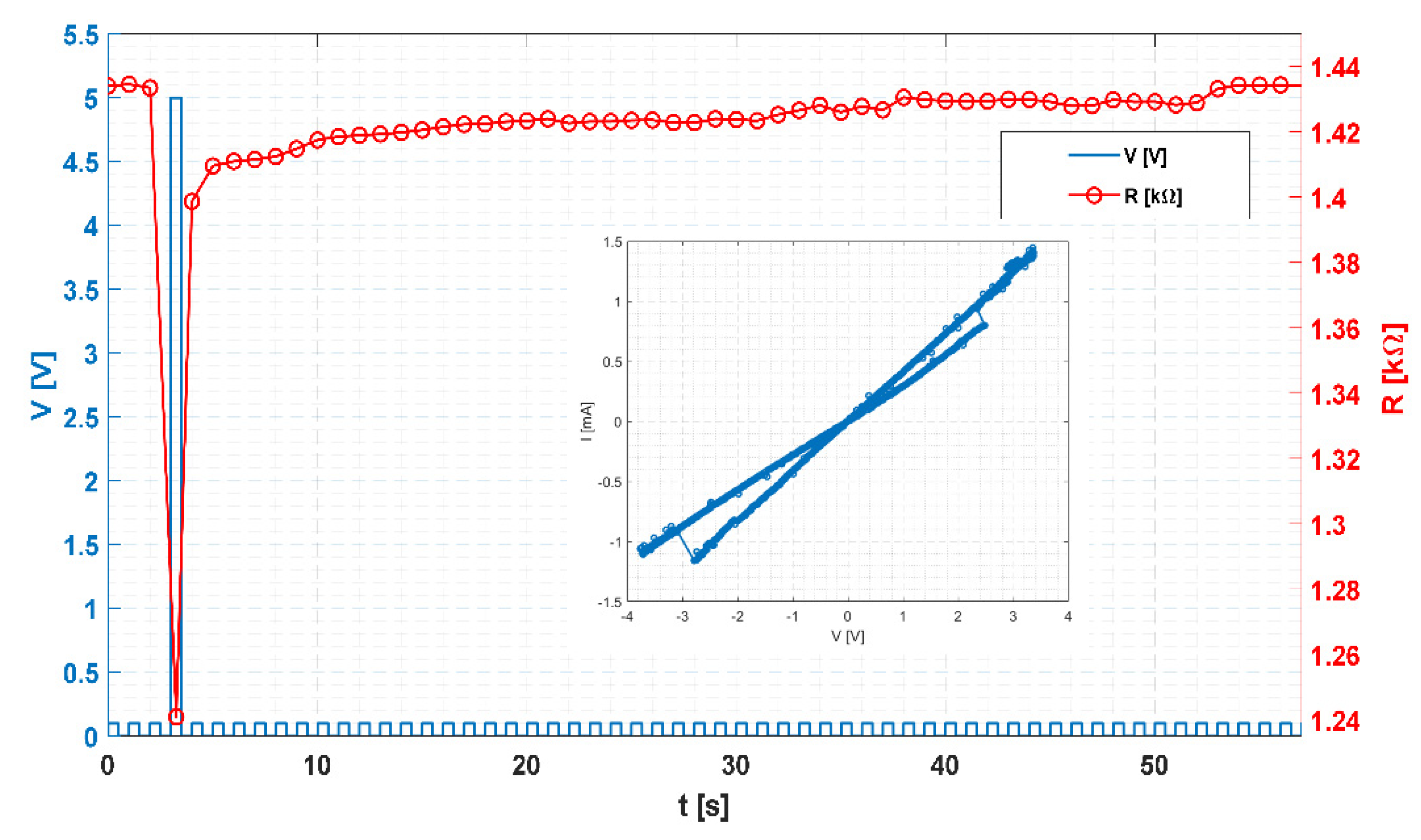
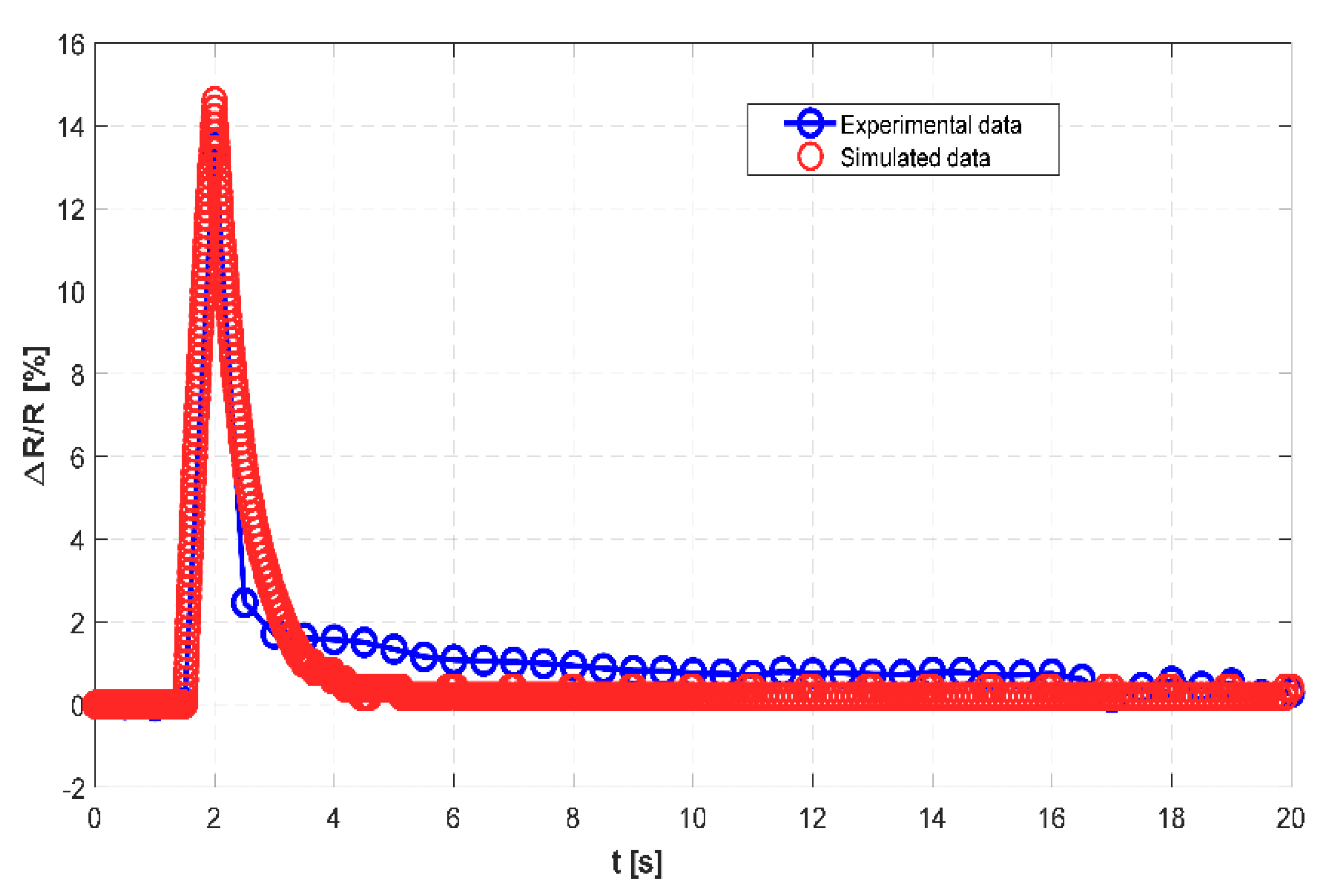
4. Experimental Results and Discussion

In the following section, we report experimental results performed on perovskite BTO thin film memristor, by analysing device response on consecutive multiple reading pulses, and single writing pulse in order to test volatility behaviour. We also examined the dynamic response of LIF artificial neurons composed of physical memristor with intrinsic capacitance value and external shunt resistance. Experimental results are compared with numerical results from LIF memristive SPICE model.
Firstly, a typical volatility test [17,18], was performed on a BTO memristor composed of a train of reading pulses and a single writing pulse, as is shown in Figure 5, where red circles correspond to measured resistance values. Initial resistance R0 of this device is ~1.43 kΩ estimated by application of low-voltage reading pulses of 0.1 V, prior to writing event. BTO memristor was further stimulated using a single above-threshold pulse with the amplitude of 5 V, which switches the memristors in LRS state (~1.2 kΩ). Afterwards, a sequence of low-voltage reading pulses was applied, revealing finite characteristic relaxation time τr ~60 s. After this time, the device returns to the initial state R0. This behaviour is typical for volatile memristors, indicating that after the stimulus is turned off, the device returns to the HRS state in a finite time period. In realized Pt/BTO/Pt device, diffusion of oxygen vacancies could lead to changes of electrical properties within the material [36], which resembles the ionic diffusion process controlling neuron channel conductance [37]. Both analogue-type switching [16] and threshold switching [38,39] was observed in volatile memristors [40]. Due to the low off-to-on resistance ratio (~1.5) and moderately steep transition between the resistance states (Figure 5 inset), realized device could be classified as an analogue switching volatile device [40].
In Figure 6 we included both simulated and experimental values of normalized resistance response upon the previously explained shown pulse train cycles. Simulation was performed in LTspice simulator on volatile memristor model, presented in Section 3, with the following parameters: RON = 1.5 kΩ, ROFF = 2 kΩ, uV = 10−10 cm2/Vs, D = 100 nm corresponding to sample properties. As fitting parameters, we used electrical parameters of x-module Cx, Rx, i.e., components of the volatile cell, which determines the amount of volatile switching and relaxing period [23], respectively. Results, illustrated in Figure 6, show good agreement between experimental and simulated data. Existing discrepancies in the decay rate may originate from intrinsic device capacitance as well as the parasitic capacitance induced through measurement setup.
For a simple LIF circuit, an additional capacitor and resistor are included in the neuron model. Recent studies show that external capacitance can lead to a prominent delay in integration time [17], thus we use the intrinsic memristor’s capacitance, whose value is estimated to ~1 nF, using an impedance analyzer for the frequency range of interest. The extracted simulation parameters and frequency-dependent capacitance value were used as input parameters for SPICE simulation of LIF neuron, Figure 7.
The firing dynamic of the artificial neuron circuit could be analyzed using pulse train stimulation as proposed in [16,17]. In this experimental study, we applied multi-pulse voltage stimulation, Vs (frequency 10 Hz, amplitude 6 V, pulse duration 50 ms), Figure 8. Actuation voltage is divided between shunt resistor R and memristor-capacitor parallel connection. In the experimental setup as described in the materials and method section, current response is estimated according to values of voltage across constant resistor R, Vr, see Figure 8b. During the fourth pulse (see Figure 8a), the voltage across the memristor (including intrinsic capacitance), Vm drops down from ~3.8 V to ~3.5 V which occurs as a consequence of memristor switching to LRS state (RON ≈ 1.5 kΩ). Namely, pulse actuation induces conduction modulation within diffusive memristor, which will eventually turn the device to on state and change the Vm value. At the same time, ~0.33 s, the current through the circuit increases starting from 2 mA to 2.36 mA, which is determined according to values of voltage Vr across constant resistor od 1 kΩ (see Figure 8b). An increase in current during pulse stimulation is interpreted as a firing event [16,17], yet due to the limited performance of BTO physical devices, specifically low off-to-on resistance ratio, this is not a very pronounced effect. It is worth noting that the amplitude of actuation voltage in our experimental studies was chosen in order to more easily reveal switching time, as for lower voltage values, the off-to-on resistance ratio of the diffusive memristor is decreased.
The additional peripheral circuit could be placed after the artificial neuron, in order to distinguish a spike event from an integration period. Solutions using comparator and pulse generator [16] or Schmitt trigger-based amplifier [15], already presented in literature, allow spike events to occur only when the input signal reaches the predefined threshold value. Certainly, improved performances of volatile memristor eliminate the need for a peripheral circuit in LIF neuron as presented in [17].
In Figure 8c,d SPICE simulation results of the LIF circuit are illustrated with the parameters extracted from normalized resistance timing characteristics (Figure 6) and properties of the BTO memristor. Regarding memristor voltage value transition, the initial voltage value is 3.69 V, while the final state amounts to 3.49 V, reached at 0.32 s (Figure 8c). Moreover, SPICE simulation results allow extraction of memristor current, without the need for usage of optimization tools for separation of memristive and capacitive effect which is required in the circuit design process [15]. Figure 8d illustrates memristors’ current (Ix(Memristor:plus)) increases at ~0.32 s from 2.11 mA to 2.49 mA, which is in good agreement with the experimental analysis (see Figure 8b for comparison). Gradual changes of simulated memristors voltage and current values (Figure 8c,d) before reaching the stable state can not be detected through experimental results due to limitations of measuring equipment. After the pulse train is turned off the device returns to its initial state in finite relaxation time.

5. Conclusions

In summary, we have implemented our new window function in the existing model of the volatile memristor in the SPICE simulation environment and included it in a simple leaky integrate-and-fire neuron circuit applicable in all-memristive neural networks. Simple LIF circuit uses inherent volatility of resistive switching element to provide decay of local gradient potential, as a leaky term in short term memory, therefore no additional blocks are required. Performed simulations demonstrate that the model can capture biological neuron dynamic: spatiotemporal integration task, firing function and leakage, i.e., forgetting functionality. The neuron model can also illustrate the influence of neuron resistance (synaptic weight) and membrane capacitance on firing behaviour and integration time. Verification was performed through comparison with an experimental study using Pt/BaTiO3/Pt diffusive/volatile memristor. In a physical LIF circuit, the intrinsic capacitance of the diffusive memristor is utilized as an integration element. Results show good agreement between model and experimental study for both resistance decay rate of volatile memristor itself and firing behaviour of LIF circuit. Demonstrated SPICE simulation of LIF allows decoupling of individual component influence of spiking behaviour and contributes to the enhancement of design of complex memristive neuromorphic architectures.

Author Contributions

Conceptualization, N.M.S. and S.D.; methodology, N.M.S. and D.L.S.; software, N.M.S.; validation, N.M.S., J.S.B. and S.D.; investigation, N.M.S., D.L.S. and S.D.; resources, N.M.S., S.D. and J.S.B.; data curation, N.M.S. and J.S.B.; writing—original draft preparation, N.M.S., J.S.B., S.D. and D.L.S.; writing—review and editing, N.M.S., J.S.B., S.D. and D.L.S.; visualization, D.L.S., J.S.B. and N.M.S.; supervision, S.D. All authors have read and agreed to the published version of the manuscript.

Funding

This work was supported in part by the European Union’s Horizon 2020 Research and Innovation Programme under the Grant Agreement 856967, and in part by the Serbian Ministry of Education, Science and Technology Development and the Faculty of Technical Sciences, the Department of Power, Electronics and Communication, under Grant “Razvoj i primena savremenih metoda u nastavi i istraživačkim aktivnostima na Departmanu za energetiku, elektroniku i telekomunikacije”, 2022.

Data Availability Statement

The data presented in this study are available on request from the corresponding author.

Acknowledgments

Authors are thankful to Branimir Bajac from Biosense Insititute, the University of Novi Sad for providing samples of Pt/BaTiO3/Pt for experimental study.

Conflicts of Interest

The authors declare no conflict of interest. The funders had no role in the design of the study; in the collection, analyses, or interpretation of data; in the writing of the manuscript, or in the decision to publish the results.

Appendix A

SPICE CODE for volatile memristor
*Volatile Memristor Model
*Copyright 2021 FTS UNS MEMR Research Group
.param Ron=1 Roff=100k uv=1e-10 D=10n qp=300e-9 qn=-300e-9 Rint=15k
+ k={uv*Ron/D**2} deltaR={Roff-Ron} p=10
.param x0={(Roff-Rint)/(Roff-Ron)} y0={(Roff-Rint)/(Roff-Ron)} z0=0
*New window functions
.func fours(x)={(1-(2*x-1)**2)/(1-(2*x-1)**2+(2*x-1)**(2*p))}
.func
iy(y,v,z)={if(v>0,if(z>qp,I(Emem)*uv*Ron*fours(y)/D**2,0),if(z<qn,I(Emem)*uv*Ron*fours(y)/D**2,0))}
.subckt memristor_vol 1 2 x y z
*terminal cell
Roff 1 aux {Roff}
Emem aux 2 value={-deltaR*v(x)*I(Emem)}
*end of terminal cell
*x-module
Gx 0 x value={I(Emem)*uv*Ron*fours(v(x))/D**2}
Cx x 0 0.5 IC={x0}
Rx x 3 1
Enov 3 0 value={v(y)}
*end of x-module
*y-module
Gy 0 y value={iy(v(y),v(x),v(z))}
Cy y 0 1 IC={y0}
*end of y-module
*z-module
Gch 0 z value={I(Emem)}
Cz z 0 1 IC={0}
Rz z 0 0.1
*end of z-module
.ends memristor_vol

References

  1. Krestinskaya, O.; James, A.P.; Chua, L.O. Neuromemristive circuits for edge computing: A review. IEEE Trans. Neural Netw. Learn Syst. 2020, 31, 4–23. [Google Scholar] [CrossRef] [PubMed] [Green Version]
  2. Xu, W.; Wang, J.; Yan, X. Advances in memristor-based neural networks. Front. Nanotechnol. 2021, 3, 20. [Google Scholar] [CrossRef]
  3. Sung, C.; Hwang, H.; Yoo, I.K. Perspective: A review on memristive hardware for neuromorphic computation. J. Appl. Phys. 2018, 124, 151903. [Google Scholar] [CrossRef] [Green Version]
  4. Schuman, C.D.; Potok, T.E.; Patton, R.M.; Birdwell, J.D.; Dean, M.E.; Rose, G.S.; Plank, J.S. A survey of neuromorphic computing and neural networks in hardware. arXiv 2017, arXiv:1705.06963. [Google Scholar]
  5. Zhang, Y.; Wang, X.; Friedman, E.G. Memristor-Based circuit design for multilayer neural networks. IEEE Trans. Circuits Syst. I Regul Pap. 2018, 65, 677–686. [Google Scholar] [CrossRef]
  6. Pantazi, A.; Woźniak, S.; Tuma, T.; Eleftheriou, E. All-Memristive neuromorphic computing with level-tuned neurons. Nanotechnology 2016, 27, 355205. [Google Scholar] [CrossRef] [PubMed]
  7. Chua, L. Memristor, Hodgkin-Huxley, and edge of chaos. Nanotechnology 2013, 27, 383001. [Google Scholar] [CrossRef] [PubMed]
  8. Gerasimova, S.A.; Belov, A.I.; Korolev, D.S.; Guseinov, D.V.; Lebedeva, A.V.; Koryazhkina, M.N.; Mikhaylov, A.N.; Kazantsev, V.B.; Pisarchik, A.N. Stochastic memristive interface for neural signal processing. Sensors 2021, 21, 5587. [Google Scholar] [CrossRef] [PubMed]
  9. Tan, Y.; Wang, C. A simple locally active memristor and its application in HR neurons. Chaos 2020, 30, 053118. [Google Scholar] [CrossRef]
  10. Rozenberg, M.J.; Schneegans, O.; Stoliar, P. An ultra-compact leaky-integrate-and-fire model for building spiking neural networks. Sci. Rep. 2019, 9, 11123. [Google Scholar] [CrossRef] [Green Version]
  11. Hodgkin, A.L.; Huxley, A.F. A quantitative description of membrane current and its application to conduction and excitation in nerve. J. Physiol. 1952, 117, 500–544. [Google Scholar] [CrossRef] [PubMed]
  12. Yi, W.; Tsang, K.K.; Lam, S.K.; Bai, X.; Crowell, J.A.; Flores, E.A. Biological plausibility and stochasticity in scalable VO2 active memristor neurons. Nat. Commun. 2018, 9, 4661. [Google Scholar] [CrossRef] [PubMed]
  13. Ascoli, A.; Demirkol, A.S.; Tetzlaff, R.; Slesazeck, S.; Mikolajick, T.; Chua, L.O. on local activity and edge of chaos in a NaMLab memristor. Front. Neurosci. 2021, 15, 651452. [Google Scholar] [CrossRef] [PubMed]
  14. Kornijcuk, V.; Lim, H.; Seok, J.Y.; Guhyun, K.; Seong, K.K.; Kim, I.; Choi, B.J.; Jeong, D.S. Leaky integrate-and-fire neuron circuit based on floating-gate integrator. Front. Neurosci. 2016, 10, 212. [Google Scholar] [CrossRef] [PubMed]
  15. Guo, T.; Pan, K.; Sun, B.; Wei, L.; Yan, Y.; Zhou, Y.N.; Wu, Y.A. Adjustable leaky-integrate-and-fire neurons based on memristor-coupled capacitors. Mater. Today Adv. 2021, 12, 100192. [Google Scholar] [CrossRef]
  16. Yang, J.; Wang, R.; Wang, Z.; .Ma, Q.; Mao, J.; Ren, Y.; Yang, X.; Zhou, Y.; Han, S. Leaky integrate-and-fire neurons based on perovskite memristor for spiking neural networks. Nano Energy 2020, 74, 104828. [Google Scholar] [CrossRef]
  17. Wang, Z.; Joshi, S.; Savel’ev, S.; Song, W.; Midya, R.; Li, Y.; Rao, M.; Yan, P.; Asapu, S.; Zhuo, Y.; et al. Fully memristive neural networks for pattern classification with unsupervised learning. Nat. Electron. 2018, 1, 137–145. [Google Scholar] [CrossRef]
  18. Wang, Z.; Joshi, S.; Savel’ev, S.; Jiang, H.; Midya, R.; Lin, P.; Hu, M.; Ge, N.; Strachan, J.P.; Li, Z.; et al. Memristors with diffusive dynamics as synaptic emulators for neuromorphic computing. Nat. Mater. 2017, 16, 101–108. [Google Scholar] [CrossRef] [PubMed] [Green Version]
  19. Lu, Y.-F.; Li, Y.; Li, H.; Wan, T.Q.; Huang, X.; He, Y.H.; Miao, X. Low-Power artificial neurons based on Ag/TiN/HfAlOx/Pt threshold switching memristor for neuromorphic computing. IEEE Electron Device Lett. 2020, 41, 1245–1248. [Google Scholar] [CrossRef]
  20. Midya, R.; Wang, Z.; Zhang, J.; Savel’ev, S.E.; Li, C.; Rao, M.; Jang, M.H.; Joshi, S.; Jiang, H.; Lin, P.; et al. Anatomy of Ag/Hafnia-based selectors with 1010 nonlinearity. Adv. Mater. 2017, 29, 1604457. [Google Scholar] [CrossRef] [PubMed] [Green Version]
  21. Jiang, H.; Belkin, D.; Savel’ev, S.E.; Lin, S.; Wang, Z.; Li, Y.; Joshi, S.; Midya, R.; Li, C.; Rao, M.; et al. A novel true random number generator based on a stochastic diffusive memristor. Nat. Commun. 2017, 8, 882. [Google Scholar] [CrossRef] [PubMed] [Green Version]
  22. Giotis, C.; Serb, A.; Stathopoulos, S.; Michalas, L.; Khiat, A.; Prodromakis, T. Bidirectional volatile signatures of metal–oxide memristors—Part I: Characterization. IEEE Trans. Electron Devices 2020, 67, 5158–5165. [Google Scholar] [CrossRef]
  23. Berdan, R.; Lim, C.; Khiat, A.; Papavassiliou, C.; Prodromakis, T. A memristor SPICE model accounting for volatile characteristics of practical ReRAM. IEEE Electron Device Lett. 2014, 35, 135–137. [Google Scholar] [CrossRef]
  24. Giotis, C.; Serb, A.; Stathopoulos, S.; Prodromakis, T. Bidirectional volatile signatures of metal-oxide memristors—Part II: Modeling. IEEE Trans. Electron Devices 2020, 67, 5166–5173. [Google Scholar] [CrossRef]
  25. Wang, W.; Laudato, M.; Ambrosi, E.; Bricalli, A.; Covi, E.; Lin, Y.H.; Ielmini, D. Volatile resistive switching memory based on Ag ion drift/diffusion part I: Numerical modelling. IEEE Trans. Electron Devices 2019, 66, 3795–3801. [Google Scholar] [CrossRef]
  26. Wang, W.; Laudato, M.; Ambrosi, E.; Bricalli, A.; Covi, E.; Lin, Y.H.; Ielmini, D. Volatile resistive switching memory based on Ag ion drift/diffusion—Part II: Compact modelling. IEEE Trans. Electron Devices 2019, 66, 3802–3808. [Google Scholar] [CrossRef]
  27. Dautovic, S.; Samardzic, N.; Juhas, A.; Ascoli, A.; Tetzlaff, R. On Window Functions for Ideal Generic Memristor. 2022; unpublished. [Google Scholar]
  28. Dautovic, S.; Samardzic, N.; Juhas, A.; Ascoli, A.; Tetzlaff, R. Simscape and LTspice models of HP ideal generic memristor based on finite closed form solution for window functions. In Proceedings of the 28th IEEE International Conference on Electronics Circuits and Systems (ICECS), Dubai, United Arab Emirates, 28 November–1 December 2021. [Google Scholar]
  29. Bajac, B.; Vukmirovic, J.; Tripkovic, D.; Djurdjic, E.; Stanojev, J.; Cvejic, Z.; Škorić, B.; Srdić, V.V. Structural characterization and dielectric properties of BaTiO3 thin films obtained by spin coating. Process. Appl. Ceram. 2014, 8, 219–224. [Google Scholar] [CrossRef]
  30. Joglekar, Y.N.; Wolf, S.J. The elusive memristor: Properties of basic electrical circuits. Eur. J. Phys. 2009, 30, 661–675. [Google Scholar] [CrossRef] [Green Version]
  31. Prodromakis, T.; Peh, B.P.; Papavassiliou, C.; Toumazou, C. A versatile memristor model with nonlinear dopant kinetics. IEEE Trans. Electron. Devices 2011, 58, 3099–3105. [Google Scholar] [CrossRef]
  32. Biolek, Z.; Biolek, D.; Biolkova, V. SPICE model of memristor with nonlinear dopant drift. Radioengineering 2009, 18, 210–214. [Google Scholar]
  33. Kvatinsky, S.; Friedman, E.G.; Kolodny, A.; Weiser, U.C. TEAM: ThrEshold adaptive memristor model. IEEE Trans. Circuits Syst. I Regul. Pap. 2013, 60, 211–221. [Google Scholar] [CrossRef]
  34. Singh, J.; Raj, B. An accurate and generic window function for nonlinear memristor models. J. Comput. Electron. 2019, 18, 640–647. [Google Scholar] [CrossRef]
  35. Li, Q.; Serb, A.; Prodromakis, T.; Xu, H. A memristor SPICE model accounting for synaptic activity dependence. PLoS ONE 2015, 10, e0120506. [Google Scholar] [CrossRef] [PubMed] [Green Version]
  36. Dawson, J.A. Dynamical insights into oxygen diffusion in BaTiO3 and SrTiO3. Phys. Status Solidi B 2020, 257, 1900422. [Google Scholar] [CrossRef]
  37. Chang, T.; Jo, S.; Wei, L. Short-Term memory to long-term memory transition in a nanoscale memristor. ACS Nano 2011, 5, 7669–7676. [Google Scholar] [CrossRef] [PubMed]
  38. Sokolov, A.S.; Ali, M.; Riaz, R.; Abbas, Y.; Ko, M.J.; Choi, C. Silver-Adapted diffusive memristor based on organic nitrogen-doped graphene oxide quantum dots (N-GOQDs) for artificial biosynapse applications. Adv. Funct. Mater. 2019, 29, 1807504. [Google Scholar] [CrossRef]
  39. Abbas, H.; Abbas, Y.; Hassan, G.; Sokolov, A.S.; Jeon, Y.R.; Ku, B.; Kang, C.J.; Choi, C. The coexistence of threshold and memory switching characteristics of ALD HfO2 memristor synaptic arrays for energy-efficient neuromorphic computing. Nanoscale 2020, 12, 14120–14134. [Google Scholar] [CrossRef] [PubMed]
  40. Wang, R.; Yang, J.; Mao, J.; Wang, Z.; Wu, S.; Zhou, M.; Chen, T.; Zhou, Y.; Han, S. Recent advances of volatile memristors: Devices, mechanisms, and applications. Adv. Intell. Syst. 2020, 2, 2000055. [Google Scholar] [CrossRef]
Figure 1. (a) Proposed novel window function in the used model of memristor; (b) Current–voltage characteristics of model with novel window function for N = 1, 2 and 3. Simulation parameters: i(t) = Imcos(ωt), Im = 1 mA, ω = 2π rad/s, ROFF = 1 kΩ, RON = 100 Ω, k = 104 C−1.
Electronics 11 00894 g001
Figure 2. Memristive leaky integrate–and–fire artificial neuron and biological neuron counterpart.
Electronics 11 00894 g002
Figure 3. Simulated response of LIF circuit with volatile memristor on voltage pulse actuation: Memristance R M (upper graph), memristor’s current i M (middle graph) and the voltage across memristor v M (bottom graph).
Electronics 11 00894 g003
Figure 4. Simulation of firing dynamics of memristive LIF artificial neuron under different stimulus and variable membrane capacitance and neuron resistance. (a) V a = 1   V ,     T o n = 1   ms , T p = 2   ms , C = 50   nF , R = 10   k Ω ,     I m a x = 320   µ A ; (b) V a = 1   V , T o n = 1   ms ,     T p = 2   ms , C = 500   nF , R = 10   k Ω ,     I m a x = 600   µ A ;   (c) V a = 1   V ,     T o n = 0.25   ms ,     T p = 0.5   ms , C = 500   nF , R = 10   k Ω , I m a x = 1   mA ;   (d) V a = 1   V , T o n = 1   ms ,     T p = 2   ms , C = 500   nF , R = 5   k Ω , I m a x = 2.68   mA .
Electronics 11 00894 g004
Figure 5. Volatility test of BTO memristor: reading pulses with low amplitude combined with single writing pulse. Inset- current-voltage characteristics of perovskite memristor.
Electronics 11 00894 g005
Figure 6. Simulated and experimental data of normalized resistance change upon a single writing pulse.
Electronics 11 00894 g006
Figure 7. LIF neuron simulation circuit with volatile memristor.
Electronics 11 00894 g007
Figure 8. Experimental (a,b) and simulated response of LIF neuron circuit with volatile memristor under multiple pulses voltage actuation. (a) Voltage across memristor-experimental analysis; (b) voltage across constant resistor-experimental analysis; (c) voltage across memristor–simulation analysis; (d) memristor current–simulation analysis.
Electronics 11 00894 g008
Table 1. Comparison between different window functions.
Different Window FunctionsJoglekar [30]Prodromakis [31]Biolek [32]Kvatinsky [33]Singh
[34]
This Paper
SymmetricYesYesYesNot necessarilyYesYes
Resolve boundary conditionsNoPractically YesYesPractically YesYesPractically Yes
Accounts for non-linear effectsPartiallyPartiallyPartiallyYesPartiallyPartially
Scalability 0 ≤ fmax (x) ≤ 1NoYesNoNoYesPartially *
Fits memristive device modelL/N/TEAML/N/TEAML/N/TEAMTEAML/N/TEAML/N/TEAM
Note: L—Linear ion drift, N—Non-linear ion drift, TEAM—Threshold adaptive memristor. * Easily extended to Yes using multiplicative constant.
Table 2. Memristor’s subcircuit model parameters.
R x C x C y R z C z
1   Ω   0.5   F 1   F 0.1   Ω 1   F
Publisher’s Note: MDPI stays neutral with regard to jurisdictional claims in published maps and institutional affiliations.

