Article

Enhanced Robots as Tools for Assisting Agricultural Engineering Students’ Development

by
Dimitrios Loukatos
*,
Maria Kondoyanni
,
Ioannis-Vasileios Kyrtopoulos
and
Konstantinos G. Arvanitis
Department of Natural Resources Management and Agricultural Engineering, Agricultural University of Athens, 75 Iera Odos Str., Botanikos, 11855 Athens, Greece
*
Author to whom correspondence should be addressed.
Electronics 2022, 11(5), 755; https://doi.org/10.3390/electronics11050755
Submission received: 26 January 2022 / Revised: 22 February 2022 / Accepted: 26 February 2022 / Published: 1 March 2022
(This article belongs to the Special Issue Trends in Educational Robotics)

Abstract

:
Inevitably, the rapid growth of the electronics industry and the wide availability of tailored programming tools and support are accelerating the digital transformation of the agricultural sector. The latter transformation seems to foster the hopes for tackling the depletion and degradation of natural resources and increasing productivity in order to cover the needs of Earth’s continuously growing population. Consequently, people getting involved with modern agriculture, from farmers to students, should become familiar with and be able to use and improve the innovative systems making the scene. At this point, the contribution of the STEM educational practices in demystifying new areas, especially in primary and secondary education, is remarkable and thus welcome, but things become quite uncertain when trying to discover efficient practices for higher education, and students of agricultural engineering are not an exception. Indeed, university students are not all newcomers to STEM and ask for real-world experiences that better prepare them for their professional careers. Trying to bridge the gap, this work highlights good practices during the various implementation stages of electric robotic ground vehicles that can serve realistic agricultural tasks. Several innovative parts, such as credit card-sized systems, AI-capable modules, smartphones, GPS, solar panels, and network transceivers are properly combined with electromechanical components and recycled materials to deliver technically and educationally meaningful results.

1. Introduction

New technologies that continuously appear have a strong impact on people’s lives, reshaping the professional sectors; even the farming sector has been altered during the last years, exploiting new techniques for agricultural production, such as IoT, automation systems, and robotics. Big agricultural manufacturing companies, have in their agendas the evolution to Agriculture 5.0 for the next decade, assuming that robots are the next, cleverer generation of farm machines [1], making the understanding of smart systems a necessity, especially for the people involved in the farming sector, such as farmers, students at agricultural universities, and agronomists. Agricultural robots’ acceptability increased in the COVID-19 era due to the labor shortage and social distancing [2], although the need for robots will not be temporary and will affect the fruit and vegetable production methods post-pandemic [3].
As indicated by teams of experts such as the USA National Research Council, agricultural education should assist in the creation of a 21st-century workforce able to address many of the modern critical economic and environmental challenges [4]. The most important of the pillars of Agriculture 5.0, such as programming, networking, global positioning systems (GPS), enhanced data processing, interconnection, autonomy, artificial intelligence (AI), human–robot interaction, and the use of smart devices [5], are present in a modern agricultural robotic vehicle. Similar vehicles can also contribute to the study of renewable energy sources, such as solar panels. For these reasons, students of agricultural engineering should understand the way that these systems operate, in order to become better prepared for their role in a digitally transformed agricultural sector. Unfortunately, robotic systems for farming purposes are quite complex and need a combination of different components and the precise synchronization of subsystems in order to work in field conditions and tackle the challenges of a real environment [6], and thus their understanding is also a quite challenging task.
Educational robotics and the STEM (Science, Technology, Engineering, and Mathematics) approach, in general, have proven their capability to engage students in the implementation of minimal systems and to the understanding of their functionalities [7,8]. The development of a robotic system, as an educational activity, contributes to the ability to design a system, combine different components, and solve real challenges, such as economic and environmental limitations, safety issues, and construction constraints [9]. The mutual benefits of combining STEM practices and agricultural education objectives are many and significant [10,11]. Nevertheless, there are problems that should be faced, such as the lack of a general model to share common principles and the lack of collaborative scripts to split students into effective sub-teams. Similarly, the incorporation/documentation of the DIY (Do-It-Yourself) culture to the robotic curricula is not efficient enough, despite its high value in delivering better learning outcomes through the interaction with real-world objects and the experience of construction [8]. Furthermore, the engineering concept remains more difficult to communicate [11,12]. Additionally, there is an apparent gap between demonstrating systems to secondary education and university students [13]. Students in higher education need to learn about systems beyond the class environment, which can work in actual field conditions and tackle real problems, thus meaning the construction of larger and smarter robots. It is worth mentioning that these robotic vehicles are performing better than initially expected. Indeed, an additional outcome is that similar university laboratory efforts can lead to results with considerable commercial perspectives, such as in the case of the Thorvald multipurpose robot [14].
In this regard, the purpose of this research is to highlight the feasibility and benefits of utilizing modern technologies that university students should know, in order to make them more effective in their future professional role of understanding/evaluating/creating innovative agricultural systems. The latter goal is served by letting engineering students get acquainted with the main design/implementation steps and the structural parts of custom robots that exhibit behaviors similar to the commercial ones. For this reason, students of agricultural engineering were involved in the development of two autonomous robotic vehicles of realistic size, one vehicle for spraying and inspecting the plants and another for carrying a plastic pallet with the harvested fruits, operations that are amongst the most important ones in modern agricultural robotics [15]. Thankfully, as the technology advances, the products get better, and the costs drop, making the necessary components widely available for low-cost construction implementations. Added to this, the relevant supporting communities are flourishing, and many open software platforms exist for efficiently programming the controlling parts of the discussed robots [16].
This article is the last one delivered by our team that discusses the implementation of experimental agricultural robots of realistic potential and, in contrast with the previous, more technical ones, provides a better view from an educational perspective. More specifically, by utilizing as the source of material these robotic constructions, the current study is acting as a magnifying lens that focuses on the details of the process of meticulously combining a wide set of both innovative and conventional electronic, electric, mechanical, and recycled components, in order to create two comparatively simple and cheap robots that are capable of typical real-world agricultural operations. In this way, students and future professionals are better motivated and prepared for the digital transformation of agriculture. Finally, the corresponding evaluation results are also reported. In other words, this research does not intend to provide the directions for delivering fully functional commercial products but rather to put emphasis on the steps of obtaining efficient and useful engineering skills through participation in the construction of agricultural robotic vehicles and to highlight the impact of similar activities on students’ professional development.
The rest of this article is organized as follows: Section 2 highlights the pedagogical settings and the technical background. Section 3 presents the role of the robots’ key implementation elements and provides directions that guide, motivate, and facilitate students through the deployment process. Section 4 is dedicated to characteristic technical experiences and evaluation results from the technological and educational perspective. Finally, Section 5 contains the most important concluding remarks.

2. Methodology

In response to the dynamics previously described, the research approach being presented is an attempt to highlight methods for increasing the efficiency of agricultural engineering education by combining innovative technical content outcomes with well-performing pedagogical practices.

2.1. Educational Settings

During the almost three-year-long period of the core robotic activities, four groups of people were involved:
  • Professors of agricultural engineering;
  • Students during their final thesis;
  • Students during their internship period;
  • Students during their curricular activities.
The latter category of students attended a combination of the courses: “Applications of Informatics in Agriculture”, “Measurements and Sensors”, “Electronics and Microprocessors”, “Precision Agriculture”, “Applications of Artificial Intelligence in Agriculture”, “Automatic Control Processes”, and “Applied Automatic Control”. Most students were from 20 to 25 years old, both males and females, while some postgraduates were slightly above 50 years old. In each semester, lasting about 4 months, approximately 25% of each lecture was dedicated to hands-on activities for the development of different parts of the robotic vehicles.
The objective of getting involved in the design and implementation of electric robotic vehicles of realistic size was difficult to be addressed by simply dividing students into typical STEM laboratory teams (i.e., four teams of 3–4 persons each, per classroom). Furthermore, due to the heterogeneity of the participating people and the occasional spacial and temporal constraints caused by the COVID-19 pandemic, not all the students had to contribute to the same degree in the implementation of these robots. Despite these difficulties, a team formation process was necessary as it increases cooperation efficiency.
More specifically, targeted at creating effective sub-teams, the students were encouraged to express their interests; they openly discussed during the ice-breaking and brainstorming phase and took part in short tasks to reveal their styles and personalities, with emphasis on the crafting and programming fields, as well seeking information, presenting, and coordinating skills. During the team assembly, a dominant priority was to select people of diverse, but complementary, characteristics for participating in each group. This approach of forming the teams followed to a certain degree the methods and the objectives described in [17].
The professors (typically one or two persons) supervised the overall team assembly process. Typically, to more efficiently addressing the quite complex and diverse technical subtasks, 1–2 members of each team were responsible for assisting in the electromechanical layout and the wiring of the robotic vehicle; 1–2 students were responsible for assisting in the programming of the embedded computers supporting the robots′ operation; similarly, 1–2 members of each team were responsible for assisting in the development of the application for remote interaction; and 1–2 students were responsible for assisting in adding machine learning functionality. Finally, one person in each team was responsible for the coordination and documentation tasks, and for reporting the most recent findings of the team.
During the project, students were free to experiment with a variety of components similar to these that were finally fit on the robotic vehicles, (e.g., spare motors and drivers, chain wheels, embedded boards, cameras, GPS, radio interfaces, and the pairing software modules). Students had the freedom to motivate each other and learn through participation in the development of experimental software and hardware parts, while the better performing variants were incorporated into the final robotic vehicle platforms. The project follows the principles of the project-based learning model (PBL) [18], while it exploits the methods of the collaborative learning (CL) model [19]. The collaborative learning characteristics are also apparent since the students within the teams expressed their ideas and opinions and worked together to search for information, understand techniques, experiment, and implement the robotic vehicle control tasks. The more experienced students orchestrated peer learning [20] activities, thus assisting their professors. The whole methodology being adopted aims for the students to develop both hard skills (i.e., more technical ones) and soft skills such as creativity, teamwork, communication, self-confidence, and problem-solving capabilities.

2.2. Technical Background and Content

The proposed work is based on the analysis of the process of implementing agricultural robots of a realistic role and size. Thankfully, many agricultural operations are not too heavy or too complex, and thus can be performed by comparatively small and lightweight robotic constructions. Typical examples of such paradigms are spraying, fruit transportation, and crop scouting. Large, conventional farming equipment is difficult for farmers to buy on a limited budget, but smaller machines can be utilized instead [21,22], often working in swarms. The latter units also reduce the soil compaction effect [23] and, if electric, there are no polluting residues by fossil fuel engines on the crops. For these reasons, there is a strong motive for effectively addressing such simple but important agricultural operations. In this regard, two basic variants of experimental robotic vehicles were discussed, one for facilitating the fruit harvesting process by carrying a plastic pallet bin and automatically following the farmer, and another for autonomous spraying over the plants while performing, in parallel, plant scouting operations using a precise thermal camera module. Several innovative but cost-effective parts, such as credit card-sized systems, AI-capable modules, smartphones, GPS, solar panels, and network transceivers were combined with electromechanical components and recycled materials, in order to provide meaningful results.
More specifically, the first robotic project objective was the delivery of a lightweight harvester assisting vehicle, capable of both remote-manual and autonomous operation. This vehicle is described in detail in [24]. This prototype electric robotic vehicle is made of wood and metal. It is a simple three-wheel layout with two drive wheels (of 10 inches, in diameter), one at each side, and one tilling wheel (of 8 inches, in diameter) at the end of its rectangular frame, all equipped with pneumatic tires. The motors for the drive wheels were selected so the robot could match the speed of a slow-walking man on a typical farm terrain, while carrying a typical plastic pallet bin full of fruits. This robot is equipped with a GPS unit and a camera capable of performing machine vision tasks, in order to find its path among the plants and to identify the harvester/farmer. High-level control is kept using either voice commands or a tangible interface.
Similarly, the second robotic project targeted the delivery of a lightweight and flexible spraying vehicle, which is described in detail in [25]. This electric vehicle is a tall construction, intended to pass over young plants, mainly for inspecting and spraying them with fertilizers or pesticides/herbicides. The frame of this vehicle is cubic and made of wood. The front part of this spraying vehicle robot is equipped with two drive wheels, for differential steering, while two caster wheels are fixed in its rear end. As in the previous construction, two separate motors, one per side, are used for driving the robot. There are two spraying reservoirs fixed, one at each side. The front side is equipped with low-pressure spraying nozzles and a set of electric centrifugal pumps. This second robotic project uses almost the same mechanics and identical controls as the harvester-assisting vehicle, and thus is capable of efficient maneuvering among the plantation lines combining machine vision and GPS information. In addition to that, it can host a high-quality thermal camera for the detailed inspection of plants.
Both projects can offer valuable engineering experiences of both visual and textual programming of smartphone devices and embedded systems. These systems are equipped with cost-effective modules, such as inertial measurement units (IMUs) or compass units, that are widely used in modern agricultural applications (e.g., in precision agriculture); thus, all students should be familiar with them. In parallel, basic techniques for combining electric motors with mechanical parts, sensors, and efficiently driving them can be introduced. Networking experiences include understanding the role of the basic communication protocols, with an emphasis on wireless solutions and client–server architectures. The efficient position report process through a GPS or even a real-time kinematic (RTK) assisted system is also demystified. Finally, students can have the opportunity to become familiar with a working AI system and its training process, emphasizing machine vision techniques and voice command interception. The robotic variants being discussed herein performed better than expected, sometimes reaching the performance of their commercial counterparts, but this comparison is beyond the scope of this study.

3. Key Implementation Elements and Directions

In line with the dynamics previously described, this section provides directions and analyzes the role of the key elements that were used for creating comparatively simple but efficient robots.

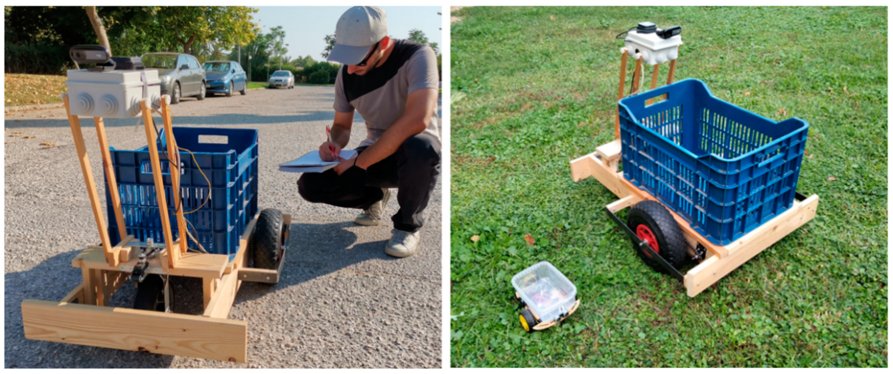
3.1. Realistic Operations Assignment

A good practice for keeping students interested in the various implementation stages of the discussed robotic constructions is to assign them simple but realistic operations, matching the corresponding activities in the agricultural fields. As mentioned in Section 2.2, many of these operations are of a light character, but this does not make them less important for the farmers. The degree that the selected operations (i.e., fruit transportation, spraying, crop scouting) are successfully implemented is central to students’ willingness to continue the specific robotic project. In this regard, technically speaking, the vehicles being constructed are designed to carry 15–20 kg cargos, or to spray, or to provide detailed plant-specific information (e.g., via precise thermal cameras), in actual agricultural field conditions, for a considerable amount of time (e.g., for at least two hours). Participants in the robotic projects should be inventive enough to implement these agricultural operations at least adequately and cost-effectively. As depicted in the left part of Figure 1, human dimensions, and even human force and speed, are used as a standard for comparing the robots being created.
These robots are of a much larger size compared with the ones used for typical STEM activities designed for K-12 students, even if they have many common design principles, as depicted in the right part of Figure 1.

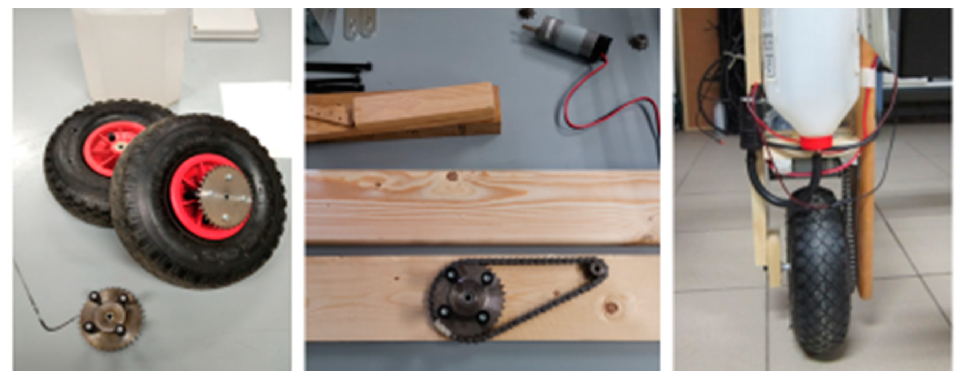
3.2. Use of Alternative Vendors and Recycling

There is a plethora of candidate components that can be used for constructing the main body of the robots and many alternative sources for supplying the necessary electromechanical equipment at affordable prices. More specifically, while the high-tech stores selling microcontrollers and innovative electronics also offer electric motors, cables, gears, screws, chains, wheels, tires, joints, and other useful accompanying parts, sometimes these components are quite expensive therein. On the contrary, these parts can be easily found, at very low prices, in local hardware stores, which are the preferred marketplace of typical craftsmen and workers. Beyond that, further parts can be bought by local malls and be slightly modified to fit the original design specifications.
The proposed robotic constructions not only favor the use of simple materials (such as wood or metal) but also encourage the reuse of retired electrical/mechanical parts and/or the utilization of recycled materials. Indeed, old parts and materials, literally “thrown away”, can turn out to be treasures throughout the whole implementation process through minor modifications. For instance, an old centrifugal car windshield pump can be turned into an efficient sprayer pump, if combined with low-pressure nozzles. Similarly, a windshield motor can work as a wheel-driving motor for the vehicle and the stepper motor borrowed from an old printer can also be used to build an accurate servo component. In this regard, Figure 2 provides good insight of the components that were used for constructing the agricultural robots discussed in this article.

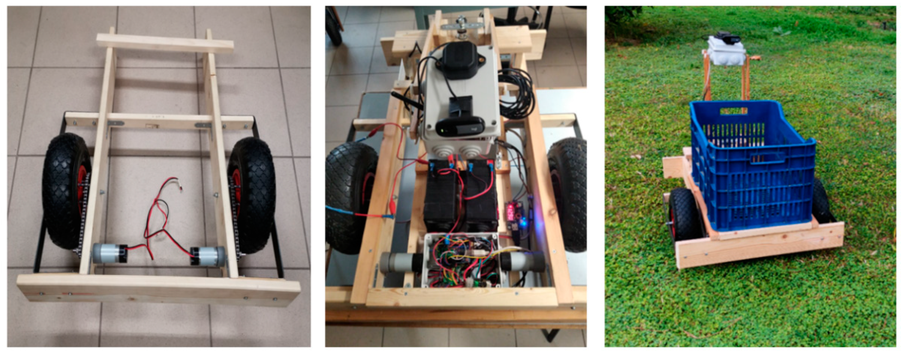
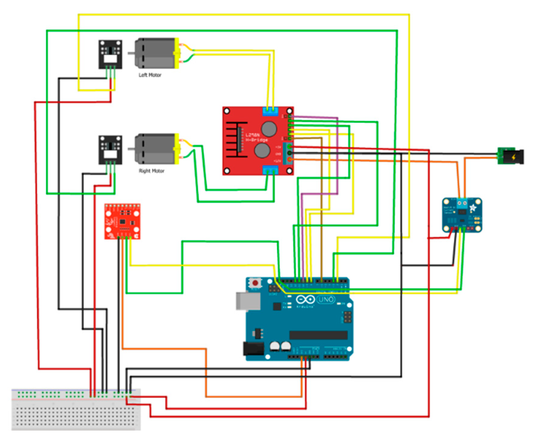
3.3. Simple but Robust Electromechanical Layout

As with the smaller scale constructions, the design of the robotic vehicles is kept as simple as possible, in order to be easily implemented by quite inexperienced persons and using simple tools. Wooden frames assisted by metal parts (i.e., joints, screws, threaded rods, bolts) are a safe choice as they are lightweight, quite flexible, and resistant to mechanical stress constructions. Furthermore, robustness can be added by placing stabilizing rods, if necessary. Wood is a quite cheap material, easy to work with, and “forgives” many of the assembly mistakes that students may make. A rectangular or a cubic frame equipped with three wheels eliminates the need for a complicated suspension mechanism, while the selection of thick pneumatic tires absorbs the terrain anomalies and withstands mud. The vehicles can surpass small obstacles without any wheel losing contact with the ground. The differential steering technique is followed to allow the robots to turn, by simply altering the rotational speed of the left drive wheel compared to that of the right drive wheel, accordingly. Figure 3 and Figure 4, especially their left and middle parts, provide explanatory material referring to the construction stages of the fruit transportation (harvester assisting) electric vehicle and the spraying (and crop scouting) vehicle, respectively.

3.4. Low-Level Controlling Mechanism

To control the low-level functions, such as stabilizing the speed of the drive wheels at a specific level, regardless of the terrain anomalies, an Arduino microcontroller is the preferred choice. This type of microcontroller has a built-in analog to digital converter (ADC) and can handle easily hardware interrupts and generate adjustable output, via the pulse width modulation (PWM) technique. The Arduino unit, typically the Uno model [26] (or the Mega model [27], for handling more signals), was adequate for driving the motors and the sprayers (through the necessary high-power electronics) and for intercepting the actual speed feedback signals, through the photo interrupters attached to the gears of the driving motors. The control of the motors was achieved through a custom proportional, integral, and derivative (PID) functionality, using the Arduino IDE environment. Furthermore, assistive data, such as ultrasonic distance sensor readings, IMU readings, and amperage and voltage readings, were easily gathered using simple sensors attached to the Arduino unit. This low-level control mechanism was connected (i.e., via serial/ USB connections) to a more advanced unit, typically implemented using a Raspberry Pi [28], which was responsible for the high-level functions.

3.5. Provision for “Smart”, High-Level Functions

Apart from the elementary control and data report functions that have to be repeated many times per second and are assigned to the low-level (i.e., Arduino-based) unit, more composite operations, which are more challenging for the students, require more powerful units to be performed fluently, such as the Raspberry Pi 3 and 4 models. Indeed, the Raspberry Pi is a quite powerful unit thus allowing the hosting and the exploitation of advanced software methods and hardware tools. For instance, artificial intelligence (AI) and especially its machine learning (ML) branch functionality, can drastically assist the path/farmer following processes, but demand high amounts of processing power. Furthermore, the robust operation of any modern robot presupposes the fusion of data provided by different sensing units (e.g., machine vision data, GPS, and IMU data) and the handling of external signals (e.g., the user’s commands), and thus methods of intercepting multiple streams of heterogeneous information simultaneously should be implemented. The communication with the low-level unit and the keeping of log files are also mandatory operations. Referring to the robotic vehicle cases being explained in this article, the latter tasks are performed quite easily by fast-performing Linux-based systems, via shell and Python scripts and libraries, C code parts, and via programming techniques using threads and network sockets. The following subsections, from Section 3.6, Section 3.7, Section 3.8, Section 3.9, Section 3.10 and Section 3.16 , provide explanatory material that highlights the high-level functionality introduced herein.

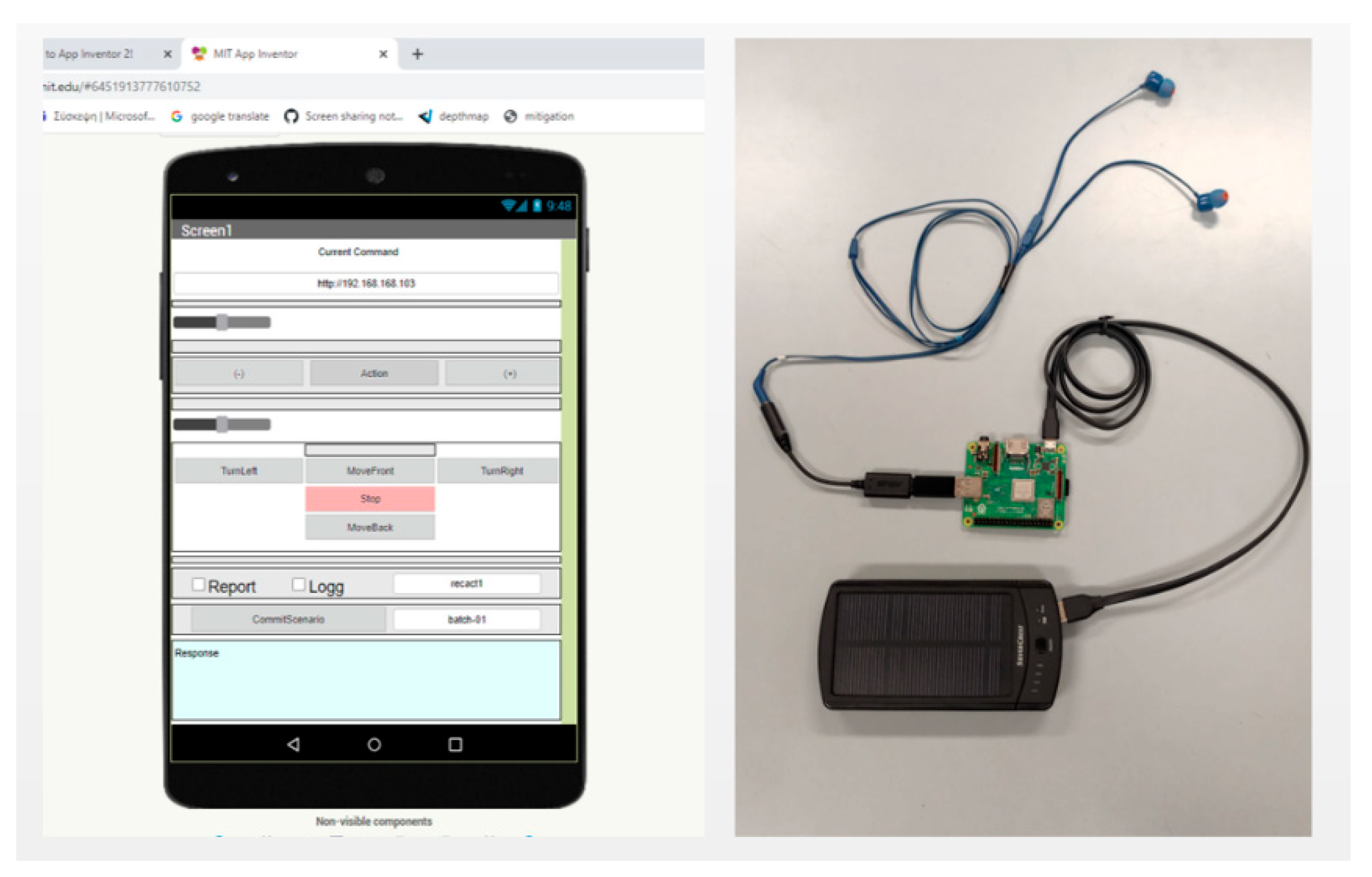
3.6. Control via Smartphones/Tablets

For controlling the robotic vehicle remotely, a mobile application was developed using the MIT App Inventor visual programming environment [29]. This cloud-based tool allows even people with minimal programming knowledge to implement efficient applications for smartphones or tablets, as it has a very easy-to-use interface. Through the latter tool, an Android Package Kit application (.apk) was built and installed on a smartphone running on the Android operating system. The left part of Figure 5 depicts the designer view of the MIT App Inventor environment while creating a robot-controlling application variant. Typically, the communication with the robot is done through a Wi-Fi link, at a frequency of 2.4 GHz, exploiting the radio interface of the tablet/smartphone. The effective range of such a communication link is comparatively limited. For better modularity purposes, a separate wireless access point (AP) module can be placed close to or on the vehicle if the smartphone is not programmed to work as such an AP. This application is suitable for conventional manual control of the robot, via its touch screen, or even for advanced control options (e.g., through voice commands), as explained in Section 3.7. Beyond that, debugging and log collection options are available, as explained in Section 3.9.

3.7. Voice Command Options

Without a doubt, the preferred way people communicate is by speaking to each other. The plan was to combine this experience of a person talking to a robotic vehicle as if it were a real, individual human being. Through an Android application, implemented using the MIT App Inventor visual programming environment, one can speak to the smartphone, giving instructions regarding the robot′s movement (turn, forward, backward) and/or starting or stopping critical functions such as spraying. According to the pilot implementation, the voice commands were sent to the robot just by pressing a button that enables a cloud-based function of Speech-to-Text. A popup window appeared, then the user started talking, giving specific orders, and the generated text that Google produced was delivered as a command string to the controlling unit of the robot, typically via a Wi-Fi interface.
Apart from this arrangement, other (locally running—offline) speech recognition methods were used involving the Python API of the SOPARE software [30] and even machine learning techniques using the Edge Impulse platform [31]. The presence of environmental noise was a critical unpleasant factor reducing the accuracy of the voice commands process. An effective solution was achieved by seeking and utilizing noise cancelation components, such as the ASUS AI Noise-Cancelling Mic Adapter [32], via USB. The right part of Figure 5 depicts the latter module, along with a small headset, connected to a Raspberry Pi unit, and a power bank, all parts of the operator’s portable voice command equipment.

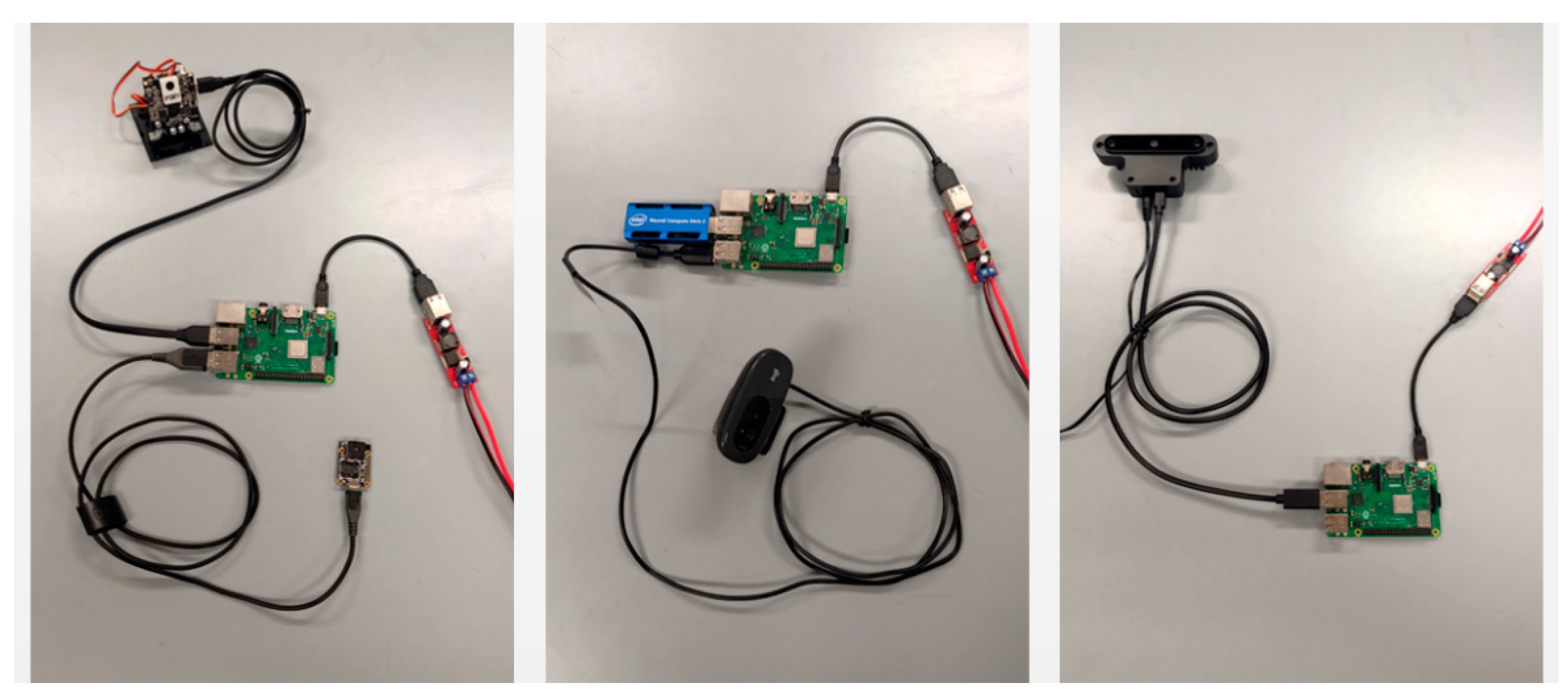
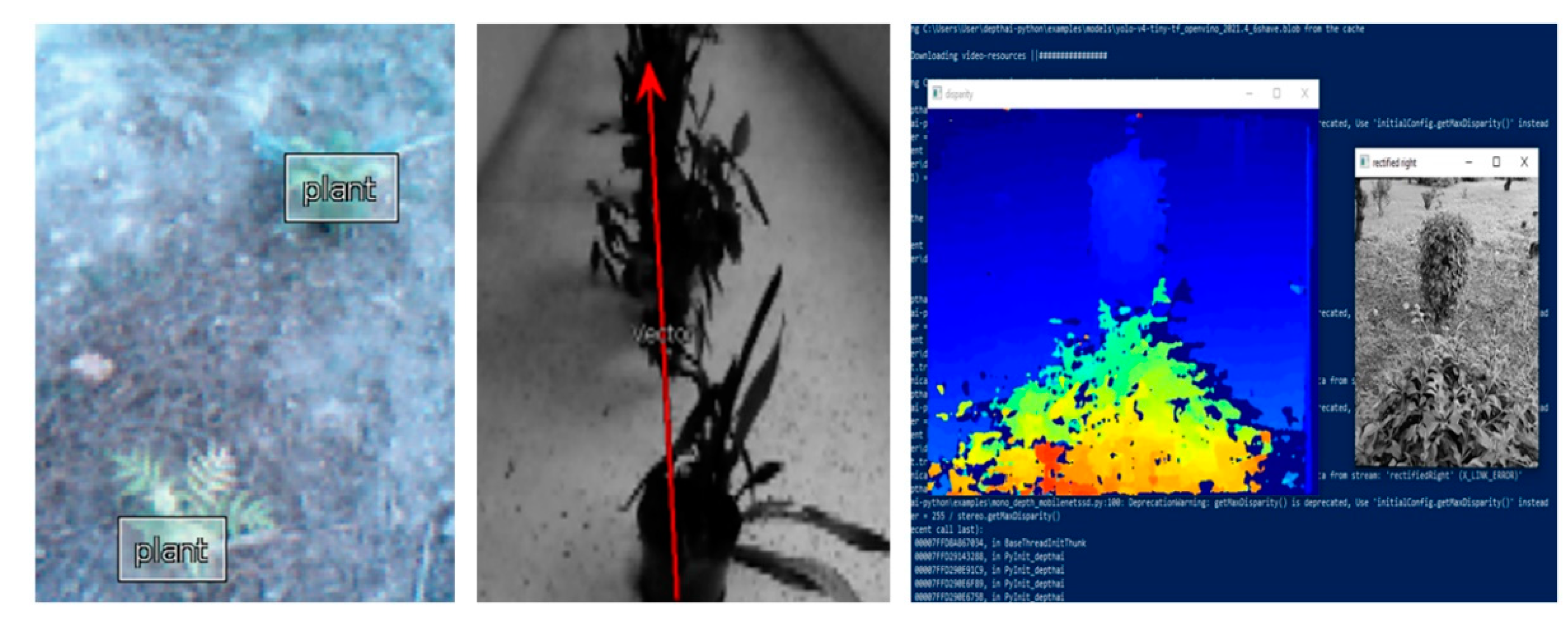
3.8. Machine Vision Options

Artificial intelligence (AI) can be utilized through a variety of simple or less simple components to provide improved autonomy for the robotic vehicles. Focusing on machine vision, initial experiments involved a camera that detects objects according to their color differences (Pixy2 camera [33]) and/or is able to intercept objects that are placed at a specific line. This camera provides an interface in C language or Python, for both Arduino IDE and Raspberry Pi environments, with the latter being preferable due to its USB connectivity characteristic. Apart from the simple Pixy2 camera, experiments were performed using a USB camera connected to a Raspberry Pi unit, assisted by a neural network operations accelerator, namely an Intel® NCS2 USB module [34]. Trained using machine learning (neural networks) through a large amount of learning data, the camera intercepts what it “sees” and can select which path or plant or person to follow. The main challenges are finding the right way to stay on the line and/or how to recognize and follow the human (farmer). To tackle these tasks, through suitable training and platform-dependent model extraction, another user-friendly solution was the use of the Edge Impulse platform. Further experiments involved a Luxonis OAK-D [35] stereovision camera which, apart from the depth map information, is capable of performing additional high-rate (i.e., up to 30 fps) machine vision (objects’ identification) operations while connected to the Raspberry Pi unit. In all cases, the comparatively simple demonstration algorithm included a typical sequence of path/plant/human identification, trajectory correction, and, possibly, action (e.g., spraying) steps. Figure 6 depicts the discussed machine vision modules, i.e., the simple Pixy2 camera, a conventional USB camera assisted by an Intel® NCS2 USB module (for fast CNN processing), and a Luxonis OAK-D module, all installed on a hosting Raspberry Pi unit.

3.9. Efficient Monitoring Functions

The ability of students and future professionals to select the optimal combination of the innovative components available for composing the best solution of a specific problem is cultivated gradually via their participation in characteristic performance evaluation activities of the digitally transformed agricultural processes. As the farming robots discussed in this article comprise many of the innovation elements of modern agriculture, the study of the performance of these vehicles is valuable towards the development of the latter ability. For this reason, the proposed implementations include and encourage the study of mechanisms for measuring the accuracy of the movements of each robot as well as its energy footprint, its response times to commands, and its requirements in bandwidth. The above goal is facilitated by the Raspberry Pi unit that can record (and transmit) large amounts of detailed performance data, co-assisted by the Arduino-provided information, and can host third-party monitoring services and tools. The topic of the positioning accuracy is directly linked with the presence of a machine vision system and the implementation of a fluent GPS mechanism. The GPS technology is very important for monitoring the spatio-temporal diversity of the agricultural processes, and thus is further explained separately in Section 3.10.

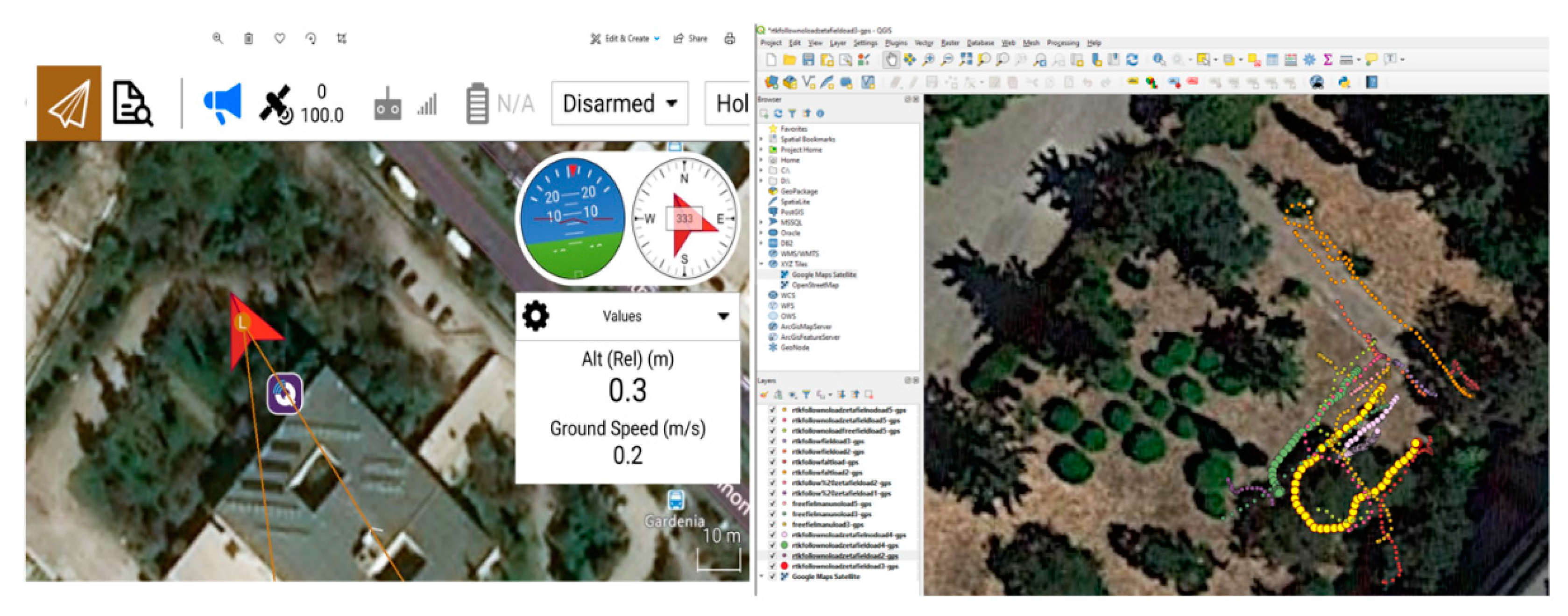
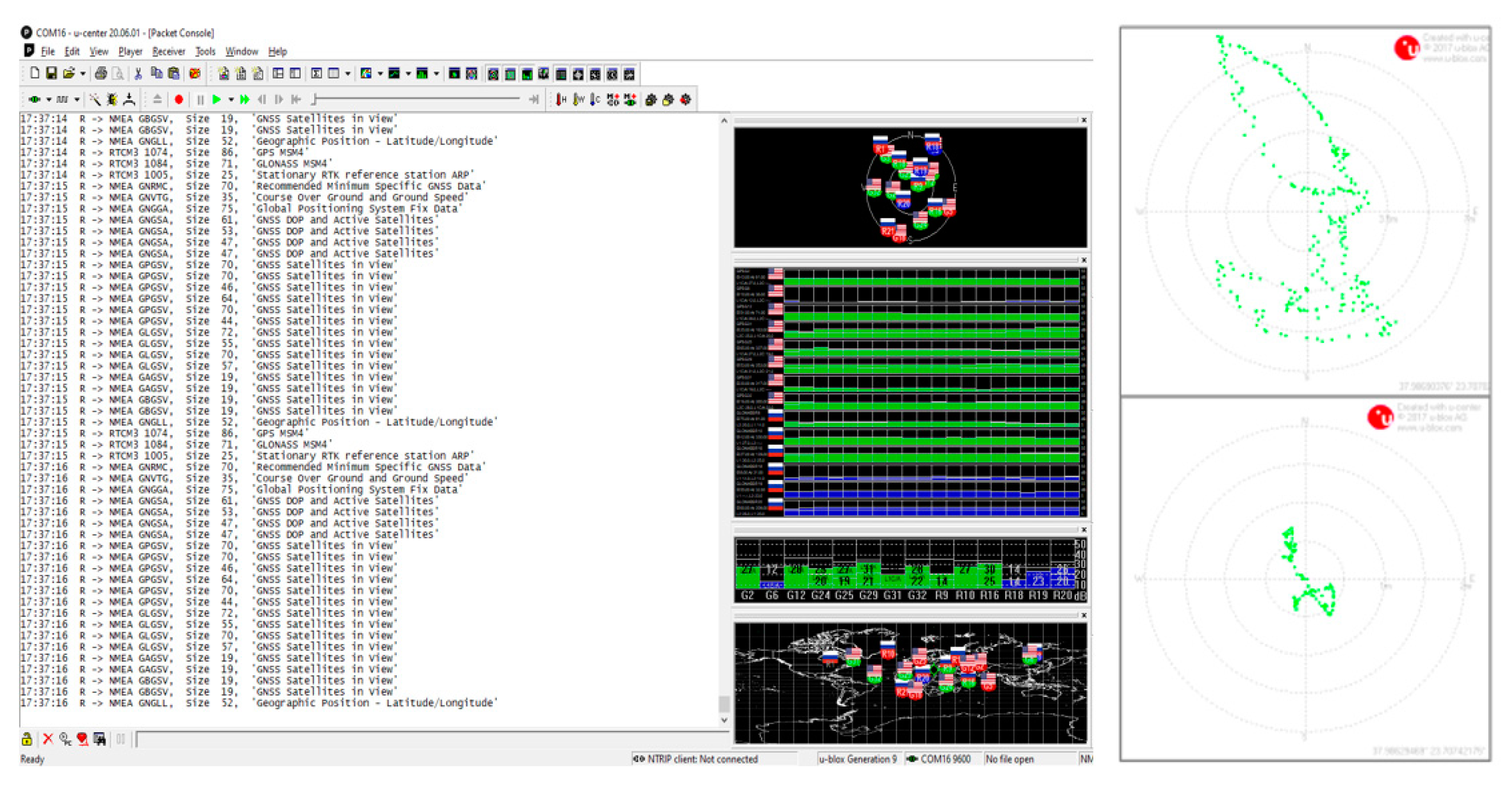
3.10. Efficient GPS Functionality

The GPS is the dominant method to determine distances and collect information about latitude, longitude, and elevation. This functionality is very useful for agriculture and thus the robots studied herein can easily host a GPS unit. A GPS module can be connected to an Arduino microcontroller via TTL serial, SPI, or I2C interfaces. Nevertheless, to not push Arduino, which may already be over-utilized by other tasks, for simplicity, and as a USB port is also the standard communication port for many GPS devices, this option was selected for connecting (and powering) the GPS module on the robot to its Raspberry Pi unit. Even a GPS with a serial output (only) can be hosted by the Raspberry Pi, assisted by a cheap USB-to-serial adapter. The choice of USB allows for faster performance evaluation, via textual or graphical output, through well-known or custom tools, such as the gpsd [36] that runs directly on the Raspberry Pi or the u-center [37] that runs on a Windows machine. The performance of the GPS is directly related to the number of satellites it “sees” in the sky, and its ability to accept correction signals for another device (RTK functionality). The latter parameters are of high didactic meaning to be observed by the students as results may vary drastically depending on the weather conditions and the quality of the modules being used. Most experimental configurations involved u-blox M8 and M9 devices [38].

3.11. Larger Driving Circuits, Batteries, and Assistance by Solar Panels

In order to support the larger electric motors of the discussed farming robots, thicker cables and more powerful and efficient driving circuits had to be used, preferably exploiting MOSFETs (metal–oxide–semiconductor field-effect transistors) and being capable of handling 5–7 amperes per channel. Apart from this, adequate power sources (batteries) were needed. The choice of batteries is vital as they provide energy for driving the vehicle, for its control unit(s), and for the sensors and the actuators being present. The selected option was a pair of sealed acid-lead batteries, of a deep discharge type, with a voltage of 12 V and a standard capacity of 7.2 Ah. They provided autonomy of about three hours for the robotic vehicles. Compared to internal combustion engines, batteries produce minimal emissions. At the same time, no money was spent on the purchase of fossil fuel, as one or two 12 V solar panel units (rated at 15 W each) were added to facilitate the autonomy of the vehicles and to minimize their environmental footprint. Lithium–polymer (LiPo) batteries are lighter and better performing but require more careful treatment and are more expensive than the acid-lead ones, and thus were not preferred for the specific experimental implementations. Despite that, LiPo-based power banks remained a useful option for feeding the critical controlling parts of the robots.

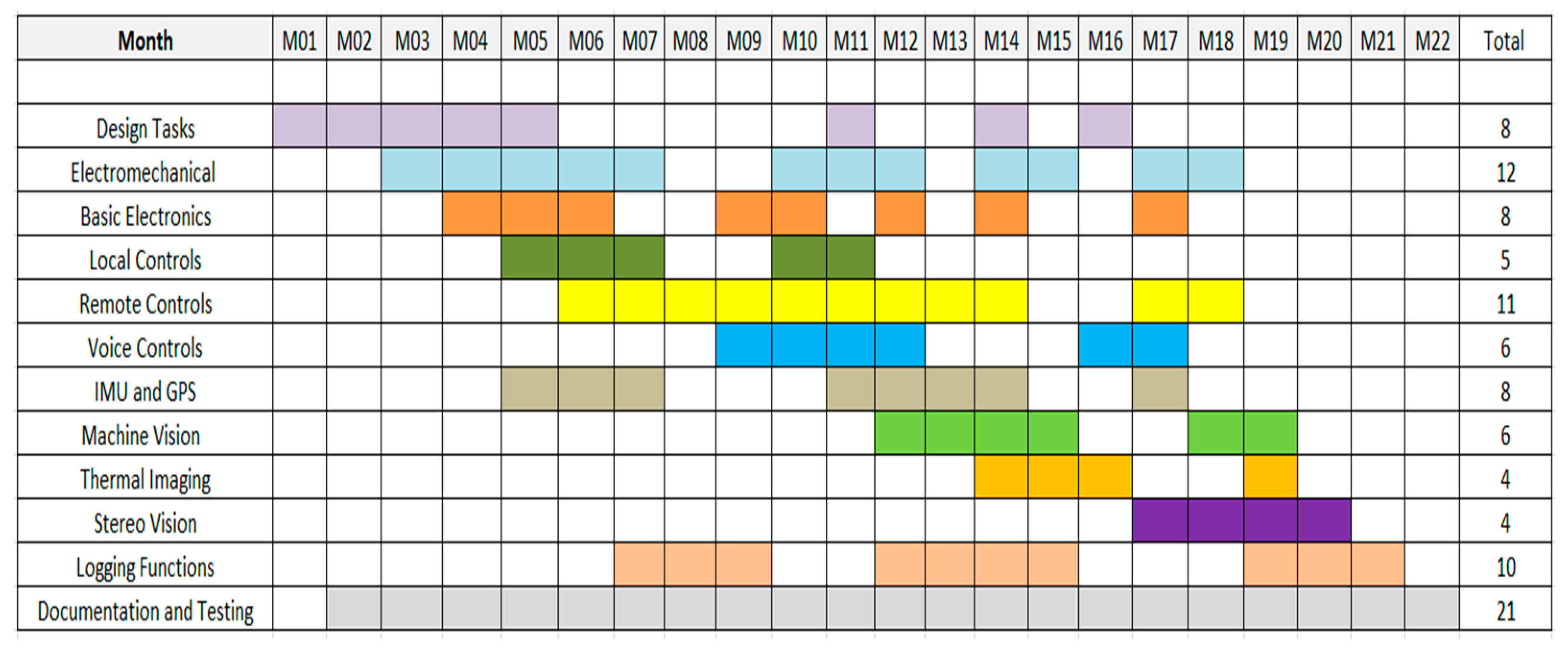
3.12. Modularity and Reusability

The selection of an Arduino-based unit for the low-level tasks, connected through USB and/or serial links with a Raspberry Pi unit, for the more composite (i.e., high-level) tasks, and communication with the user is adopted by both robotic vehicle examples presented herein. Both systems are designed to be user-friendly: they can host many innovative electronic components, they are easy-to-find, and both have flourishing supporting communities, many of which are offering educationally-oriented content. These conditions encourage fast prototyping development. Furthermore, the Arduino part can be programmed easily, even remotely, using the pairing Raspberry Pi unit connected to it [39]. These reasons counterbalance any potential disadvantage (e.g., the increased size, power consumption, and/or the higher energy/financial cost) that the Arduino–Raspberry combination might have compared to more compact and commercially oriented, embedded computer solutions.
The control units comprise two plastic boxes being interconnected, one for the Arduino and one for the Raspberry Pi, accompanied by or hosting further discrete modules, such as AI cameras, GPS/IMU units, and motor drivers. These units (and the accompanying electromechanical parts, of course) can be reused and orchestrate a wide variety of prototype constructions, according to the university laboratory settings, thus reducing the total financial cost of the educational curricula implementation. The modular character also encourages the parallel, and thus faster, development of robots’ diverse parts, as well as the study of the behavior of different combinations of modules. It is important to mention that, as with the basic electromechanical layout of the robots, the complexity of their electronics and functions should be kept low to a decent degree, because any technical implementation always requires more effort and time than what was initially planned.

3.13. COVID-19 Restrictions Considerations

The constraints of the COVID-19 pandemic have shifted the education approach to online learning, in order to cope with the lockdowns and social distancing. Findings of relevant studies indicate that students are positive in online classes, as they are more flexible and can still improve their technical skills [40]; furthermore, the combination of remote programming and hybrid lessons has demonstrated feasibility for university lessons [39]. Every challenge, such as the COVID-19 pandemic, can be seen as an opportunity for increasing creativity and rearranging teaching methods, from both an educational and technical perspective. These methods should provide to a certain degree the remote involvement of students in controlling, programming, and monitoring the main boards (e.g., Arduino, Raspberry Pi) activities, from their laptop or even from their tablet/smartphone. In the case of the two robotic vehicles being presented, many of these activities are addressed successfully via virtual network computing (VNC), secure shell (SSH), and virtual private networking (VPN) technologies and services that are implemented using cloud platforms and the high-level Raspberry Pi unit which is hosted on the robots, in a way similar to that described in [39]. For instance, the remote user, through the VNC environment, can access the Raspberry Pi and invoke the Arduino IDE environment in order to program the Arduino microcontroller, can provide driving commands via the smartphone, and can inspect the behavior of the robot through a web camera installed on it.

3.14. Priority for Safety

The cables are put into channels and the electrical parts (boards) and the batteries are protected in waterproof plastic boxes, typically of IP65 standard. Twisted pair cables and/or shielded cables are also used for critical (mainly analog) signal transfer, for eliminating interference phenomena. The cables should be of an adequate size, wherever necessary, for tackling the increased amperage needs of the robotic motors. Furthermore, efforts were made in order to eliminate the sharp edges of the construction. While the low vehicle’s maximum speed is not capable of causing serious harm, the comparatively large size of the prototypes (similar to that of a small table) and weighting 25–30 kg, should make people around them quite cautious. The implementation of functions of manual overdrive for the vehicles (typically via smartphones) is an apparent priority, while the placement of a stop switch on each robot has many times proven its value.

3.15. Fluent Documentation and Versioning

Documentation plays an important role in research and in developing projects, for tracking the process, solving problems, improving the quality, organizing, and assessing. Mainly, fluent documentation maintains and transfers knowledge by describing the parts of a system and its construction steps, assembly, programming, and operation. Occasional difficulties should be meticulously described and provided with solutions, to save time in a potential future implementation and minimize redundancies.
Figure 7 depicts a typical documentation example, that of the wiring diagram of an early (and thus non-optimal) version of the low-level control unit, made using the fritzing design environment, which is widely used in Arduino specific projects. The diagram includes the left and the right driving motors, along with a set of pairing rotational speed feedback sensors, a motor driver chip, an IMU unit (more composite navigation units of this type were fit later on the Raspberry Pi unit), and a current metering module.
All the participating teams had to present their progress to the whole at specific time intervals (e.g., every two weeks) and compose a final presentation referring to the robot’s subsystems which were under their responsibility, while a repository was created containing all the relevant explanatory material being gathered during the robot’s deployment process as well as all implementation versions, from the earliest to the latest ones. The main idea behind this organization is that everyone (the old team members also included) who would like to continue the development of the discussed vehicles do not to have to start from point zero.

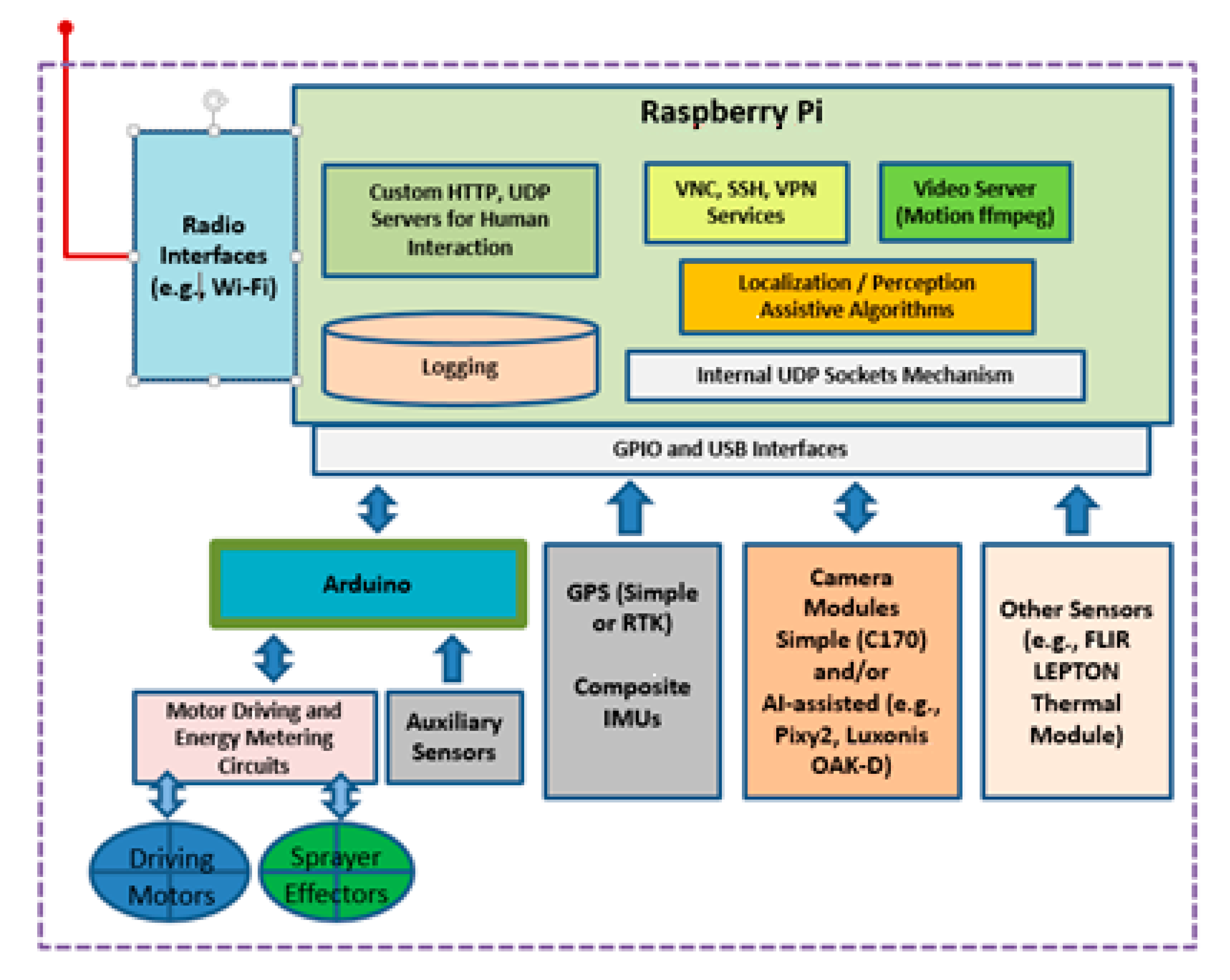
3.16. Components’ Interoperation Overview

After having separately highlighted the most important elements participating in the deployment of agricultural robots, an overview of their interoperation as a functioning whole is given. The emphasis is mainly put on maximizing usability and simultaneously maintaining simplicity and cost-effectiveness, in an educationally-friendly manner. The latter friendliness works to facilitate and to encourage the participation of the students in the selected design, implementation, and evaluation activities, fostering the acquisition of a good mixture of professional skills. Figure 8 summarizes exactly the interoperation of the various components, in order to provide an efficient and easy-to-understand functionality for the robots.
The most apparent characteristic towards simplicity, modularity, and user educational friendliness is the extended use of USB interfaces for easily connecting various sensing alternatives on the controlling unit. From a GPS module to a stereovision and AI-capable camera, such as the Luxonis OAK-D, or a sensitive thermal camera module, such as the FLIR Lepton 3.5 [41], this type of interface provides fluent connectivity via the necessary and easy to find and modify Python and/or C language libraries. The behavior of these modules can initially be understood and/or checked by third party software (via Linux or Windows operating system machines) prior to their final installation in the robot’s brain.
The main interface between the Arduino and Raspberry Pi is also of USB type, while a second serial interface is also used. This arrangement, apart from on-the-fly programming through the Arduino IDE environment which is running on the Raspberry Pi unit, allows for a wide set of debugging options. For instance, the information generated from the Arduino unit can be easily inspected through the serial monitor and/or the serial plotter components of the Arduino IDE, or via a conventional Linux-based serial console utility such as the minicom. Furthermore, during the intermediate implementation steps, the response of the low-level control unit (i.e., the Arduino) to the commands from the high-level control unit (i.e., the Raspberry Pi), can be fine-tuned by sending equivalent user-generated commands utilizing the simple serial interface.
The data provided by the advanced sensing elements, such as the RTK-capable GPS or the Pixy2/OAK-D cameras, are internally converted inside the Raspberry Pi unit to internal UDP flows that are feeding a central localization and perception software entity that can also intercept the external requests from the human operator. This fusion of information is used for the optimal maneuver and control of the robot and for relevant actions, such as spraying decisions at the presence of “green” targets beneath the vehicle. As in case of USB signals, these information flows can be easily inspected, emulated, or modified, using simple TCP/IP socket programming, typically using Python language and/or Linux shell scripts, as mentioned in Section 3.5. Finally, the Raspberry Pi is the ideal environment for hosting well-known monitoring services, facilitating the learners and the programmers, such as video streaming, VNC, SSH, and VPN, as explained in [39].

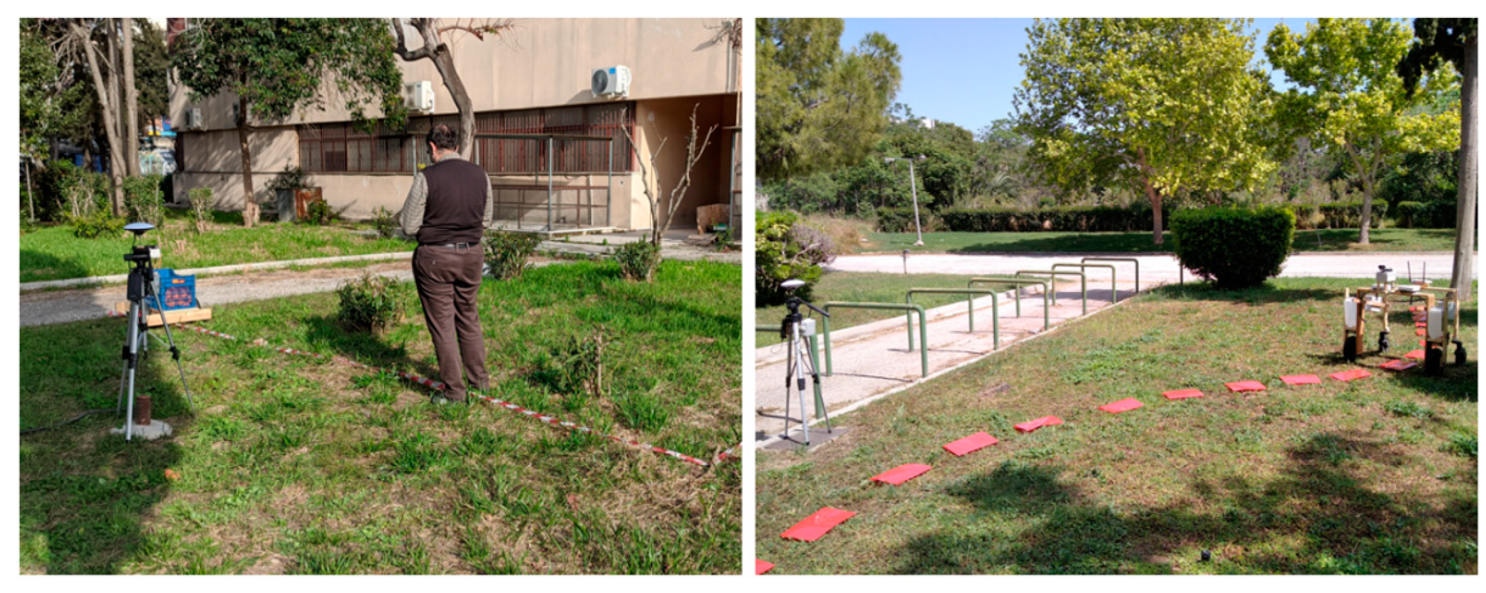
4. Experimentation, Results, and Evaluation

The two agricultural robot projects that comprise the basis for structuring this article provide a fruitful environment for learning experiences and multilevel skill assessment, covering a wide range of technical and pedagogical issues. This section does not intend to advertise the best possible performance achieved by the robots of interest, but rather to indicate the feasibility and the usefulness of the process of gathering and inspecting a wide variety of sensing and vehicle performance data. The latter objective is facilitated by the participation in the design, implementation, and testing of the robots and is of great importance as it assists students to develop critical skills and become more effective in proposing optimally working solutions for modern farmers.

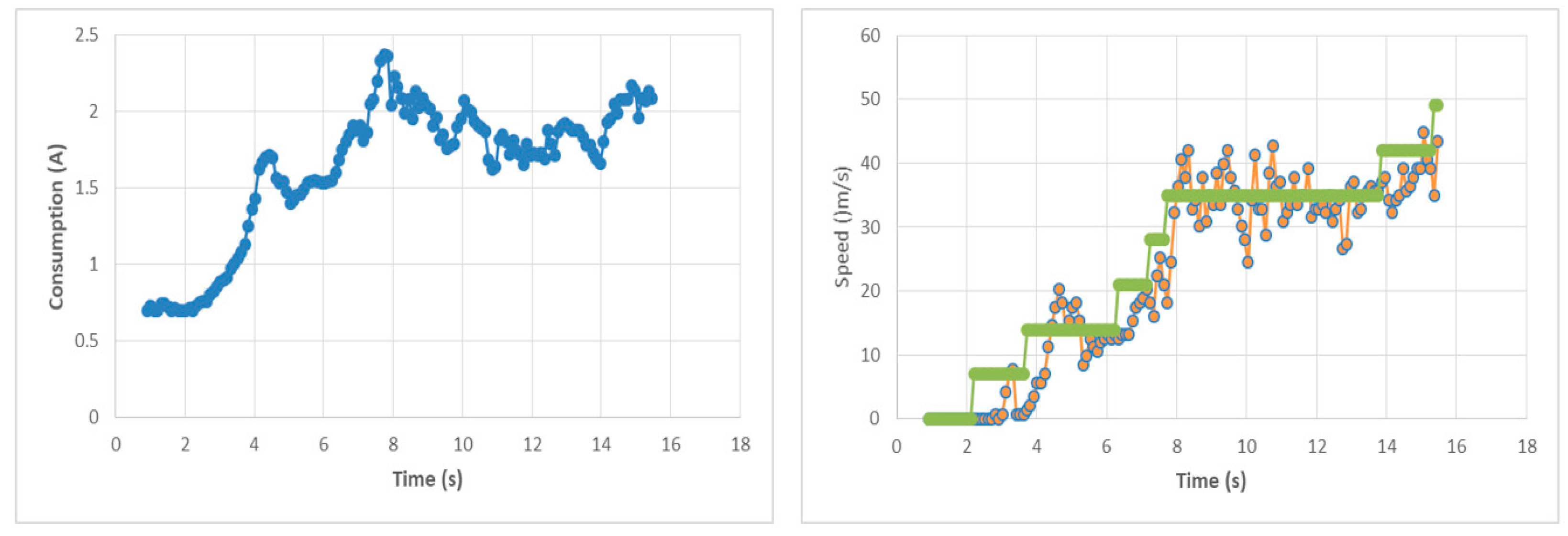
4.1. Technical Experimentation Aspect

The parts comprising the robotic vehicles were tested separately as well as the complete robots as functioning entities, in both indoor and outdoor environments, with the latter ones to be more challenging for the students. After an initial stage of testing including manual controls, locally via buttons, switches, and potentiometers fixed on the robots, the necessary operating commands were given via a remote computer console and finally using the smartphone’s touch screen. At a later stage, the vehicles responded to simple commands like “turn right” or “set speed at 0.40 m/s”, which were given by the operator’s voice, using the Android phone or a Raspberry Pi unit and the properly developed AI software [31,42]. Typically, the delay (networking and processing) in the robot’s response to these commands was below 1 s, while the success ratio to voice commands varied from below 50% to almost 90%, according to the equipment being used (e.g., good microphones and the ASUS Noise-Cancelling Mic Adapter) and to the presence/absence of noise.
The operating distance of the robots (in the manual mode), in most cases was limited by the potential of the radio link being used, i.e., it was up to 150 m in open space, when using Wi-Fi radio transceivers. This range limit was more than adequate, from an educational perspective, as its increased bandwidth capabilities were ideal for supporting the quite demanding remote video streaming and the VNC environment that required almost 1 Mbps of aggregate rate to function fluently. Further experiments utilized LoRa and UMTS radio techniques for extending the manual-mode operating range of the robotic vehicle, but this incurred quite complicated network settings that could distract students’ attention and thus were beyond the main priorities of this work.
It should be noted that students had the opportunity to experiment with several GPS device modules, which are very practical tools during the agricultural operations, even prior to installing them on the robots. The impact of the sky view conditions on their performance, especially with the absence of RTK correction signals, was remarkable. Accuracies from several meters down to a few decimeters were experienced, while the hiring of an RTK correction signal resulted in bounded deviation values of a few centimeters. Figure 9 depicts instances of the GPS modules (u-blox M8 and M9 devices) performance inspection and adjustments, using the u-center environment, via a USB connection with the hosting system.
The experimentation with machine vision techniques required the exploitation of data flows generated by the diverse camera modules. Figure 10 depicts characteristic screenshots of the diverse streaming information provided by the discussed machine vision modules, i.e., plants identification (Pixy2), vector extraction (Pixy2), and depth map extraction (Luxonis OAK-D). In all cases, the x-axis and the y-axis coordinates of the center of the object of interest (or the of area containing the objects of interest) were compared, typically against the center of the current video frame, and correction commands were generated from the high-level control unit (Raspberry Pi) to the low-level control unit (Arduino) according to the coordinate difference of these two reference points [24].
Field experiments included target-following operations, with this target to be an object, a plant (or series of them), or a human (Figure 11). An “a priori map” of the terrain the robot was moving over assisted in the whole process. These vision techniques, as well as the voice command invocation, were of great practical importance in real-world conditions, compared with the touch screen alternatives, which are more appropriate for indoor use and moderate lighting conditions.
The accuracy and responsiveness of the machine vision mechanism were also very important. For verifying this behavior, apart from the in situ visual inspection, an accurate RTK GPS was deployed, implemented using the reliable ZED-F9P module provided by SparkFun [43]. A pairing base station was also implemented, and the RTK correction data were provided via a pair of telemetry radio modules. The robot’s location readings were recorded in log files, managed by Raspberry Pi.
The accuracy of this verification mechanism was below 5 cm and the trace of the agricultural robot was visualized, at a later time, using the QGIS environment [44]. The installation of further services on the robot’s Raspberry Pi allowed the use of tools, such as the QGroundControl (QGC) [45], which are well-known to the unmanned aerial/ground vehicles (UAVs/UGVs) hobbyist community. Characteristic positioning verification results are shown in Figure 12. The best positioning/maneuvering accuracy values achieved by the robots were nearly 10 cm, assisted by the precise GPS mechanism and the machine vision techniques, with 4 frames (and thus positioning updates) per second to be the lower bound for fluent operation.
The modular and open-source nature of the experimental robots allowed for easily highlighting the strengths and the weaknesses of each configuration variant via testing. For instance, it was observed that the stepper motors initially used, although allowing for easy and precise operation, consumed too much power and produced a lot of heat. Consequently, these motors were replaced by simple, brushed DC motors that exhibited a much lower consumption, which followed the load condition changes progressively. The geared DC motors that were finally used, in pairs, for driving the discussed robotic variants (i.e., two electric motors per vehicle, one per each side), were rated as 150 rpm units and were capable of delivering a stall torque of 70 kg∙cm each. Further torque increase and speed reduction were achieved by an additional chain drive mechanism at a 3:1 ratio, thus resulting in a maximum speed of approximately 0.7 m/s and in a dragging force of more than 10 kg per side, using wheels with pneumatic tires having an external diameter of 26 cm. These characteristics allowed the robots to roll fluently on slightly inclined and rough terrains, while carrying cargos of 15–20 kg, at speeds reaching those of a slow-walking man. Indeed, students had the opportunity to acquire valuable experiences in the actual behavior of electric motors, such as inspecting the differences between the stall torque and the rated torque of a motor or understanding the ratio between motors’ amperage consumption and the mechanical stress that these motors are subjected to.
Students had the opportunity for experimentation with different PID control variants as well as algorithmic flavors utilizing adjustable coefficient values for treating the negative and the positive target speed errors differently. As clearly explained in [24] and applied in [25], for differential steering, calculations related to the geometry of each robotic variant allow for the vehicle to turn at a given speed, following an arc belonging to a circle of a preferred radius. Let vo be the desired (and known) speed (i.e., the linear velocity) of the outer wheel and ro and ri be the external and the internal radius of the circles followed by the outer and the inner wheels during this turn, respectively. The distance d between the driving wheels (which is also known) is expressed by the difference between ro and ri. Finally, as both wheels have the same orbital angular velocity and the linear velocity of the outer wheel remains equal to that of the whole vehicle just before steering, the linear velocity of the inner wheel vi can be easily computed by the d and vo quantities, for a preferred internal turning radius ri, by the following equation:
vo/ro = vi/ri or vo/(ri + d) = vi/ri or vi = vo · ri/(ri + d),
In the variant described in [24], the direction of the non-driving wheel is also adjusted dynamically so as to conform to the above orbital behavior. In situ measurements, utilizing both RTK-assisted GPS and conventional metering techniques, verified that the robotic vehicles were able to follow the turning directions with an accuracy between 5% and 10% of the ri quantity, depending on the terrain conditions. During vehicles’ cornering, resetting, or equalizing the left and right integral speed error quantities for the driving motors, immediately after reaching the target direction value, was a non-linear control practice that was comparatively easy to implement and observe using the specific robotic systems [46]. A power metering module, based on an INA219 chip [47], hosted by the Arduino, provided accurate readings every 0.1 s. Similarly, both the robot’s target and actual speed values were recorded at the same sampling rate. These readings were finally gathered at the flash memory of the Raspberry Pi unit, for further processing, while short-period averages were posted to the user’s smartphone. This logging potential is reflected in Figure 13, where an instance of 15 s of vehicle’s activity is analyzed, i.e., the amperage consumption of the robot (left) and its actual speed response to speed alteration directions (right). The flat, stepped curve (right) corresponds to the target speed directions, while the drastically fluctuating curve reflects the efforts of the speed stabilization mechanism to follow these directions. The latter mechanism is mainly using as feedback (in short-time scale) the information provided to the Arduino by the rotational speed (Hall) sensors of the driving motors.
The amperage consumption of the robots varied from 1 A to 6 A (at 12 V), with the controlling elements drawing 15 W at maximum (i.e., under the most power-consuming configuration and at peak activity), thus resulting in a total consumption between 15 W and 75 W for typical usage. The electric pumps used for the spraying robotic variant consumed 1 A each, approximately, when active. Taking into account the availability of two 7.2 Ah sealed acid-lead battery units and their discharge constraints, the discussed power consumption behavior allowed for a continuous operation of about 2 h to 3 h, while the addition of one or two solar panel units of 15 W extended by up to 25% the autonomous operation duration on a sunny day. The solar panels were more convenient and easier to install on the spraying robotic vehicle variant, accompanied by a cheap, low-wattage DC–DC voltage regulator/charger.
The financial cost of the basic equipment utilized for deploying each of the two robots did not exceed the 750€ level. This is a very affordable price level for any university laboratory budget. Apparently, the addition of high-end components, such as the OAK-D stereovision camera and the ZED-F9P RTK-capable GPS module, would almost double this amount, if both components are selected. The provision for qualitative crop scouting functionality usually demands expensive sensors and thus a typical module such as the FLIR Lepton 3.5 and its USB adapter would add almost 450€ to the cost of the spraying variant for entry-level crops scouting. The whole cost analysis is explained in Table 1, where the optional (high-end) components are printed in pale gray.
Further details referring to the technical characteristics and the performance of the robotic variants used in this study can be found in [24,25].

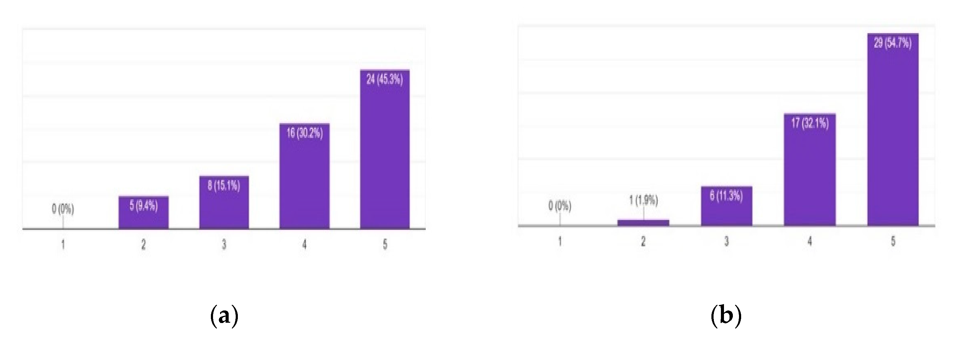
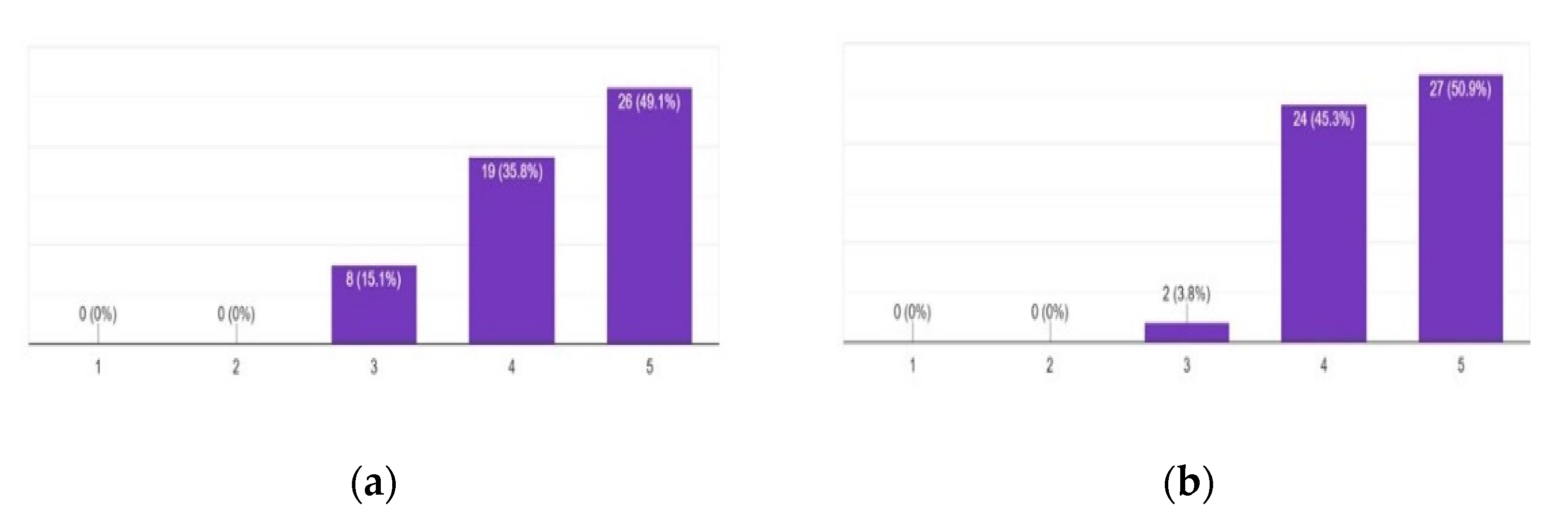
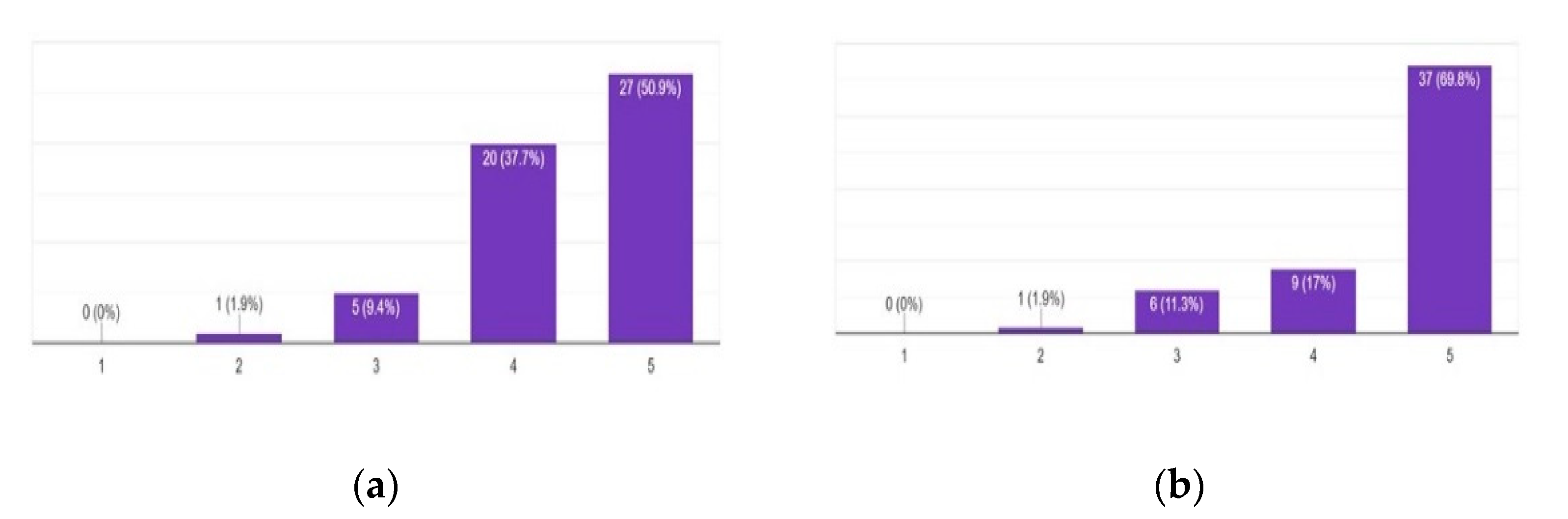
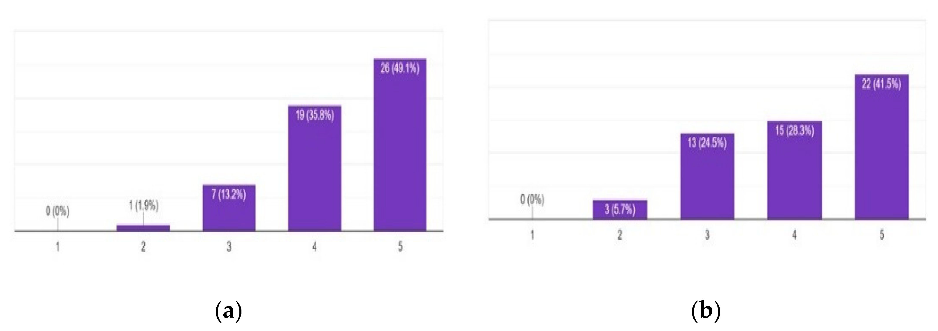
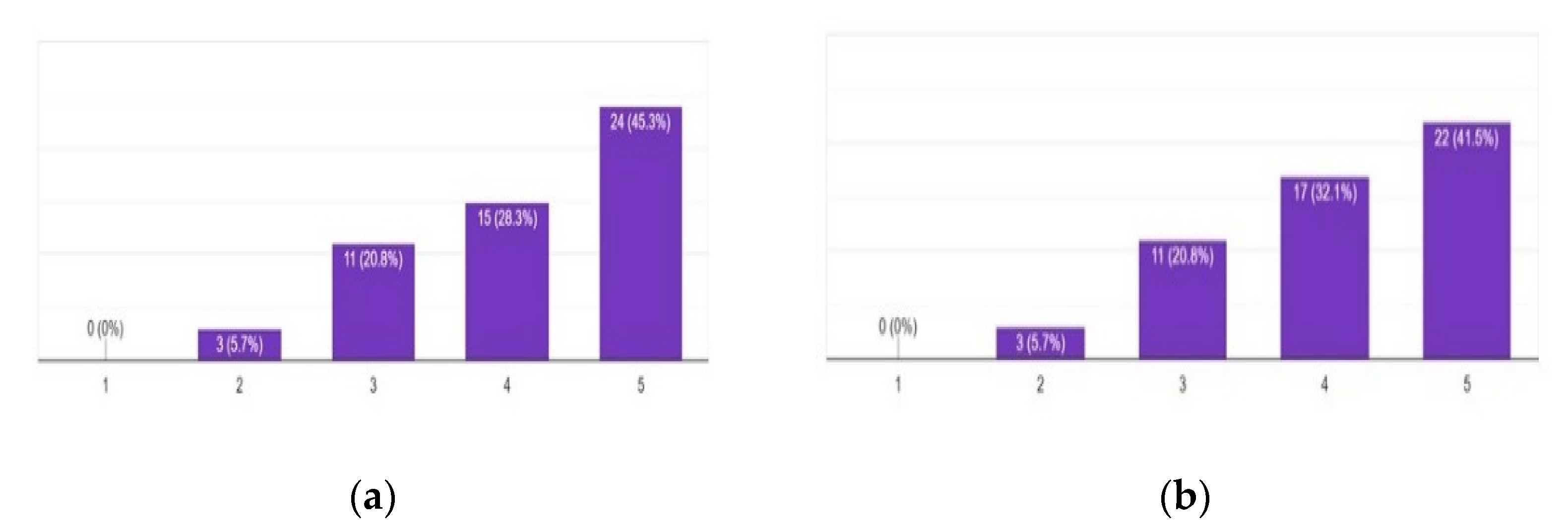
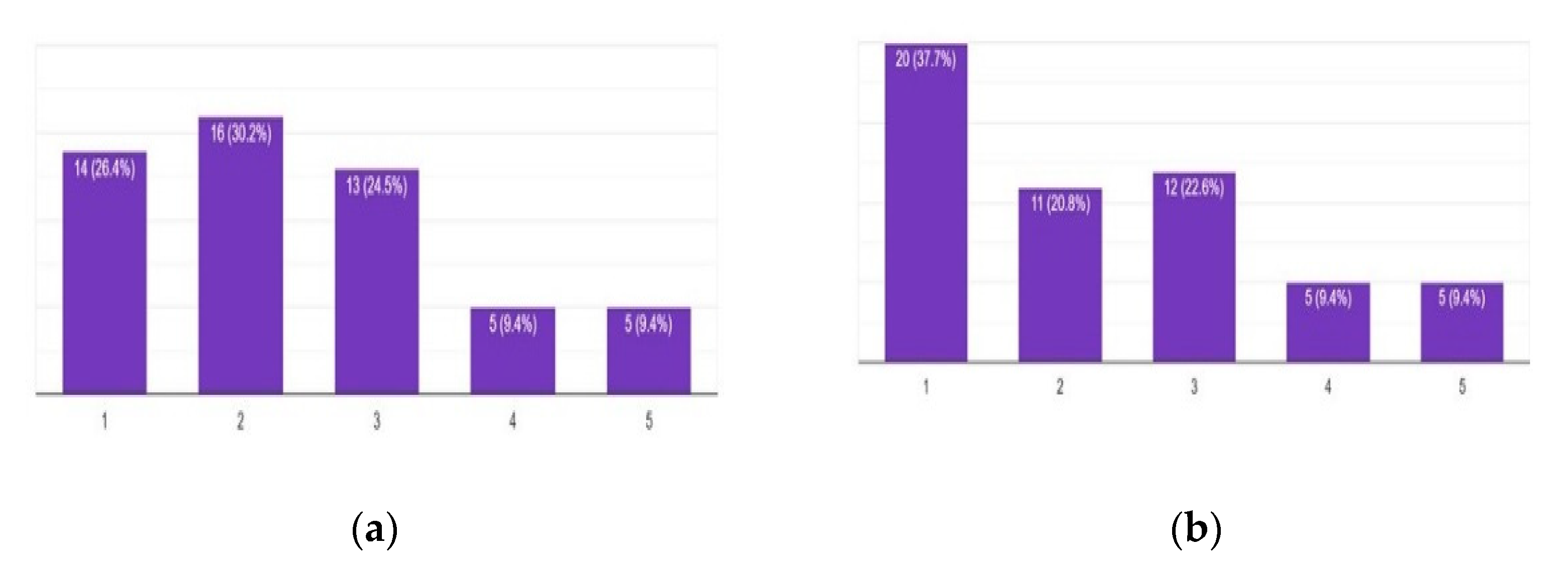
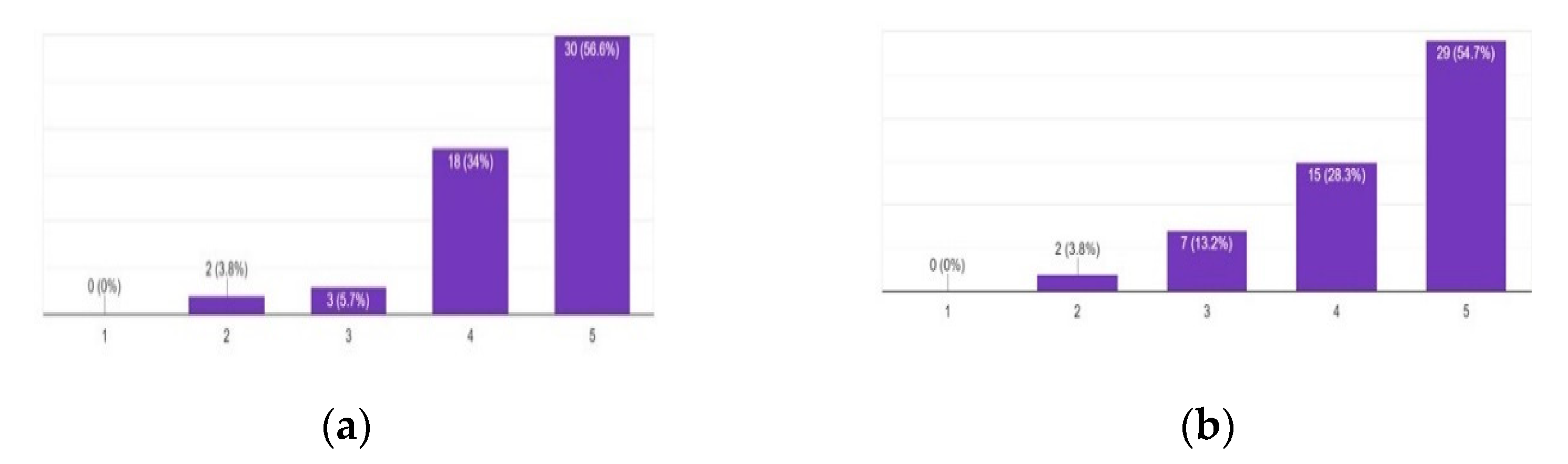
4.2. Educational Evaluation Aspect

The participation of the students in all the steps, from design to final implementation and testing, of the agricultural robots, created a meaningful learning environment encouraging the demystification of several high-end technologies that characterize modern agriculture. The modular nature of the robots being implemented allowed for the elaboration of diverse tasks in parallel. For instance, the GPS positioning accuracy could be improved simultaneously with machine vision algorithms training and cable arrangements. The diverse tasks can be enrolled in twelve categories: Design Tasks, Electromechanical, Basic Electronics, Local Controls, Remote Controls, Voice Controls, IMU and GPS, Machine Vision, Thermal Imaging, Stereo Vision, Logging Functions, and Documentation and Testing. The role of each category is directly linked with its name. The activities described in this work took place from March 2019 to November 2021, and, for better clarity, the first shock caused by the COVID-19 pandemic and the holiday intervals were subtracted, resulting in an equivalent period of 22 months of continuous project work. Figure 14 summarizes the time span of each of these twelve characteristic activities, for better comparison purposes.
It can be noticed that several activities were interrupted and continued after a few months, according to the students’ curricular priorities, the availability/delivery of components, the difficulties being experienced, and/or the requirements imposed by the other parallel tasks. The column at the right part of Figure 14 provides the equivalent continuous duration, in months, of each separate activity of the robotic projects.
A survey was also conducted to better analyze the students′ views on the platform in use, with 53 participants who were persons that took place in the activities previously presented, each to a certain degree (i.e., from newcomers to STEM to quite experienced in programming and electronic parts assembly). All the responders participated in this survey on a completely voluntary, confidential and anonymous basis. The study involved 41 males and 12 females, aged from 20 to above 50 years old, with 31 from the total 53 persons being experienced in STEM issues and 22 being inexperienced. Both undergraduate and postgraduate students’ opinions were mentioned. Aside from a beneficial discussion with these students, the people who participated in the survey were asked through questionnaires using the Likert scale [48] to assess the discussed activities. The data were then processed using the techniques outlined in [49] and plotted as classic bar charts. Figure 15, Figure 16, Figure 17, Figure 18, Figure 19, Figure 20 and Figure 21 depict the survey′s main findings. The evaluation form contained statements referring to the development of both hard skills and soft skills, as well as assessment characterizations of the whole process and the professors’/instructors’ guidance.
More specifically, the vast majority of people that were involved in the survey agreed that these systems assisted students in better understanding critical hardware and software issues (Figure 15a,b). They also agreed that the scaled-up version of the proposed system was suitable for farm usage (Figure 16a), and also more attractive as an educational activity than a smaller robot (Figure 16b).
It is worth mentioning that students did not lose their confidence during the implementation stages due to occasional failures (Figure 17a); instead, they overcame the difficulties and widened their problem-solving capacity and experiences. These failures did not make them consider that their instructors/professors were inadequate (Figure 17b). Occasional implementation failures were not suppressed but, instead, were studied meticulously as they comprise interesting learning opportunities. The teamworking experiences gained by the participants enhanced the students’ self-esteem (Figure 18a) and resulted in team bonding (Figure 18b).
The findings also indicated that students’ involvement in the design and implementation stages increased their ability to compile unknown and innovative technologies (Figure 19a) and increased their potential for documenting and communicating their work (Figure 19b). The participants’ answers also verified that the proposed activity helped students to understand the significance of the fusion of cutting-edge technologies, such as Informatics, Networking, Robotics, and Artificial Intelligence, in modern agriculture (Figure 20a). Students also improved and enriched the skills needed for their future professional careers (Figure 20b). Finally, the vast majority of participants agreed that the aforementioned activities, assisted students to better understand the objectives of the university’s curriculum (Figure 21a) and also that similar activities should be added to universities’ curricula (Figure 21b).
In Appendix A, Table A1 contains the main statements used in the evaluation forms, while means for each statement are provided to directly summarize participants’ opinions according to the corresponding five-point Likert scale findings.

4.3. Discussion

The work presented herein, in line with the multidisciplinary character of the recent research trends, has potential to be beneficial for readers originating both from areas of education and electronics. For this reason, there was an attempt to keep a good balance between presenting technical and educational content, avoiding being either imprecisely general or distractingly detailed. In this regard, the importance of properly selecting and combining innovative electronic components (and their pairing software) with more traditional parts, in order to create cost-effective but efficient robots, and thus to inspire and to assist agricultural engineering students for their future roles, was highlighted. The educational benefits from this approach were also reported via the participation of the students in a corresponding evaluation survey. The methods described can be applied to other (engineering) specialties apart from the agricultural engineering one, with minor modifications to the end effector elements (e.g., the sprayers or the plant identification algorithms). It is worth mentioning that the two robotic variants being studied performed better than initially expected, sometimes reaching the performance of their commercial counterparts, but this is beyond the scope of this work.
The design specifications and the in situ behavior of the robotic variants discussed in this article are in line with the modern trends in agricultural robotics. Indeed, similar robotic platforms have been developed by various universities, research centers, and companies, which are also smart, flexible, and consume little energy. These agricultural robots are used for data collection, crop and soil monitoring, weeding, sowing, and harvesting. Most of them are lightweight, with two to four active wheels, and they have cameras, GPS, gyroscopes, magnetometers, and moisture sensors for sensing; additionally, some of them are equipped with tools for manipulation, such as actuators and cutting tools. Detailed information on their characteristics can be found in [50,51,52,53,54]. The lightweight and possible autonomous design is a modern trend for deploying small, human potential-oriented agricultural robots that are able to work in swarms for accomplishing agricultural tasks and are quite affordable by the comparatively poor farmers and are in line with the directions for sustainable and environmentally friendly development [21,22,23,55].
The fact that necessary technologies are becoming more and more available and affordable has a considerable commercial and pedagogical impact, which should not be underestimated, but properly exploited. The students that took part in the deployment and the performance evaluation of the electric autonomous robotic ground vehicles, through the hands-on activities, gained valuable knowledge, improved their skills, and became better equipped for their professional careers. In parallel, all persons who participated were encouraged to cultivate their patience, cooperativeness, and inventiveness, while the whole process was organized so as to provide intermediate modules and results, thus encouraging participants and allowing for in-parallel development. Also, through the occasional implementation failures, students increased their collaborative and problem-solving skills.

5. Conclusions

The main contribution of this work was the improved highlighting of the feasibility and the benefits from the process of selecting, understanding, and properly combining the necessary set of key elements, while maintaining simplicity and cost effectiveness, in order to create agricultural robots with efficient roles, and thus to better motivate and enrich the experiences of the participating students. The source of material for this study was two variants of experimental robotic vehicles, sharing the same design principles, one for facilitating the fruit harvesting process by carrying a plastic pallet bin and automatically following the farmer, and another for autonomous spraying over the plants while performing, in parallel, crop scouting operations, potentially using a precise thermal camera module.
Several innovative parts, such as credit card-sized systems, AI-capable modules, smartphones, GPS, solar panels, and network transceivers, were paired with electromechanical components and recycled materials, in order to provide meaningful results, from both the technical and educational perspective. Evaluation data reflecting the experiences of the students who participated in the discussed robotic activities were also reported. More specifically, according to the relevant survey findings, the participation of the students in the corresponding design, implementation, and evaluation activities results in a good combination of soft and hard skills acquisition that better prepares them for their future professional careers as engineers and facilitators of many critical operations of the agricultural sector in the digital era, and thus similar practices should be welcomed into the curricula of universities.

Author Contributions

D.L. conceived the idea for the paper, designed most of the platform, was responsible for the implementation and validation process, and wrote several parts; M.K. assisted D.L. in the writing process and in addressing the educational evaluation process; I.-V.K. mainly assisted D.L. in the electromechanical deployment of the robots and in the technical testing stage; finally, K.G.A. helped by providing review and editing advice and addressed several administration tasks. All authors have read and agreed to the published version of the manuscript.

Funding

This research received no external funding.

Institutional Review Board Statement

Ethical review and approval were waived for this study, due to not involving identifiable personal nor sensitive data.

Informed Consent Statement

Students’ consent was waived due to not involving identifiable personal nor sensitive data.

Data Availability Statement

The data presented in this study are available upon request from the corresponding author.

Acknowledgments

The authors would like to thank the faculty and the students of the Dept. of Natural Resources Management and Agricultural Engineering of the Agricultural University of Athens, Greece, for their assistance during the implementation and testing/evaluation stages the robotic constructions being presented. They would also like to thank the CEO and the staff of the TCB Automations S.A. for their assistance in responding to various technical questions and in electronic equipment for supporting the experiments.

Conflicts of Interest

The authors declare no conflict of interest.

Appendix A

Table A1 contains the main statements used in the evaluation form, which is described in Section 4.2. Furthermore, the means of each statement are provided to measure participants’ agreement on the five-point Likert scale.
Table A1. Statements used in the evaluation form to measure participants’ agreement.
StatementsMean
The proposed application assists students to better understand hardware interconnection issues4.321
The proposed application assists students to better understand software cooperation issues4.056
The scaled-up version of the proposed system is suitable for farm usage4.135
The scaled-up version of the proposed system is more attractive as an educational activity4.097
The occasional failures during the implementation stages affect the students′ faith and cause them to lose their confidence to finish the work2.449
The occasional failures during the implementation stages make students consider that their instructors are inadequate2.317
The teamworking experience enhances the students′ self-esteem4.114
The teamworking experience results in team bonding4.396
Students′ involvement in the design and implementation stages increased their ability to compile unknown and innovative technologies4.340
Students′ involvement in the implementation stages increased their ability to document and communicate their work4.471
The proposed activity helps students to understand the significance of the fusion of Informatics, Networking, Robotics and Artificial Intelligence in modern Agriculture4.437
This activity adds on the skills needed for students′ future professional career4.339
The presented activity assists to better understand the objectives of your school or university′s curriculum4.373
Similar activities should be added to the school or university′s curriculum4.547

References

  1. Saiz-Rubio, V.; Rovira-Más, F. From smart farming towards agriculture 5.0: A review on crop data management. Agronomy 2020, 10, 207. [Google Scholar] [CrossRef] [Green Version]
  2. Cortignani, R.; Carulli, G.; Dono, G. COVID-19 and labour in agriculture: Economic and productive impacts in an agricultural area of the Mediterranean. Ital. J. Agron. 2020, 15, 172–181. [Google Scholar] [CrossRef]
  3. Shen, Y.; Guo, D.; Long, F.; Mateos, L.A.; Ding, H.; Xiu, Z.; Hellman, R.B.; King, A.; Chen, S.; Zhang, C.; et al. Robots under COVID-19 pandemic: A comprehensive survey. IEEE Access 2021, 9, 1590–1615. [Google Scholar] [CrossRef] [PubMed]
  4. National Research Council. Transforming Agricultural Education for a Changing World; The National Academies Press: Washington, DC, USA, 2009. [Google Scholar] [CrossRef]
  5. Ahmad, L.; Nabi, F. Agriculture 5.0: Artificial Intelligence, IoT, and Machine Learning, 1st ed.; CRC Press: Boca Raton, FL, USA, 2021. [Google Scholar] [CrossRef]
  6. Bechar, A.; Vigneault, C. Agricultural robots for field operations: Concepts and components. Biosyst. Eng. 2016, 149, 94–111. [Google Scholar] [CrossRef]
  7. Anwar, S.; Bascou, N.A.; Menekse, M.; Kardgar, A. A systematic review of studies on educational robotics. J. Pre-Coll. Eng. Educ. Res. J-PEER 2019, 9, 2. [Google Scholar] [CrossRef] [Green Version]
  8. Sapounidis, T.; Alimisis, D. Educational robotics curricula: Current trends and shortcomings. In Education in & with Robotics to Foster 21st-Century Skills, Proceedings of the EDUROBOTICS 2021: Educational Robotics International Conference, Siena, Italy, 25–26 February 2021; Springer: Cham, Switzerland, 2021; pp. 127–138. [Google Scholar] [CrossRef]
  9. Phan, M.H.; Ngo, H.Q.T. A multidisciplinary mechatronics program: From Project-Based learning to a Community-Based approach on an open platform. Electronics 2020, 9, 954. [Google Scholar] [CrossRef]
  10. Fisher-Maltese, C.; Zimmerman, T.D. A Garden-Based approach to teaching life science produces shifts in students’ attitudes toward the environment. Int. J. Environ. Sci. Educ. 2015, 10, 51–66. [Google Scholar]
  11. Stubbs, E.A.; Myers, B.E. Multiple Case Study of STEM in School-Based Agricultural Education. J. Agric. Educ. 2015, 56, 188–203. [Google Scholar] [CrossRef]
  12. Roehrig, G.H.; Moore, T.J.; Wang, H.H.; Park, M.S. Is adding the E enough? Investigating the impact of K-12 engineering standards on the implementation of STEM integration. Sch. Sci. Math. 2012, 112, 31–44. [Google Scholar] [CrossRef]
  13. Tan, J.T.C.; Iocchi, L.; Eguchi, A.; Okada, H. Bridging Robotics Education between High School and University: RoboCup@Home Education. In Proceedings of the IEEE AFRICON Conference, Accra, Ghana, 25–27 September 2019; pp. 1–4. [Google Scholar] [CrossRef]
  14. Grimstad, L.; From, P.J. The Thorvald II agricultural robotic system. Robotics 2017, 6, 24. [Google Scholar] [CrossRef] [Green Version]
  15. Fountas, S.; Mylonas, N.; Malounas, I.; Rodias, E.; Santos, C.H.; Pekkeriet, E. Agricultural Robotics for Field Operations. Sensors 2020, 20, 2672. [Google Scholar] [CrossRef] [PubMed]
  16. Pozzi, M.; Prattichizzo, D.; Malvezzi, M. Accessible Educational Resources for Teaching and Learning Robotics. Robotics 2021, 10, 38. [Google Scholar] [CrossRef]
  17. Borges, J.; Dias, T.G.; Cunha, J.F. A new Group-Formation method for student projects. Eur. J. Eng. Educ. 2019, 34, 573–585. [Google Scholar] [CrossRef]
  18. Markham, T. Project Based Learning. Teach. Libr. 2011, 39, 38–42. [Google Scholar]
  19. Smith, B.L.; MacGregor, J.T. What is collaborative learning. In Collaborative Learning: A Sourcebook for Higher Education; Goodsell, A.S., Maher, M.R., Tinto, V., Eds.; National Center on Postsecondary Teaching, Learning and Assessment, Pennsylvania State University: State College, PA, USA, 1992. [Google Scholar]
  20. King, A. Structuring Peer Interaction to Promote High-Level Cognitive Processing. Theory Pract. 2002, 41, 33–39. [Google Scholar] [CrossRef]
  21. King, A. Technology: The Future of Agriculture. Nat. Cell Biol. 2017, 544, S21–S23. [Google Scholar] [CrossRef] [Green Version]
  22. Shamshiri, R.R.; Weltzien, C.; Hameed, I.A.; Yule, I.J.; Grift, T.E.; Balasundram, S.K.; Pitonakova, L.; Ahmad, D.; Chowdhary, G. Research and development in agricultural robotics: A perspective of digital farming. Int. J. Agric. Biol. Eng. 2018, 11, 1–11. [Google Scholar] [CrossRef]
  23. Fountas, S.; Gemtos, T.A.; Blackmore, S. Robotics and Sustainability in Soil Engineering. In Soil Engineering; Springer: Berlin, Germany, 2010; pp. 69–80. [Google Scholar]
  24. Loukatos, D.; Petrongonas, E.; Manes, K.; Kyrtopoulos, I.-V.; Dimou, V.; Arvanitis, K.G. A Synergy of Innovative Technologies towards Implementing an Autonomous DIY Electric Vehicle for Harvester-Assisting Purposes. Machines 2021, 9, 82. [Google Scholar] [CrossRef]
  25. Loukatos, D.; Templalexis, C.; Lentzou, D.; Xanthopoulos, G.; Arvanitis, K.G. Enhancing a flexible robotic spraying platform for distant plant inspection via High-Quality thermal imagery data. Comput. Electron. Agric. 2021, 190, 106462. [Google Scholar] [CrossRef]
  26. Arduino Uno. Arduino Uno Board Description on the Official Arduino Site. 2021. Available online: https://store.arduino.cc/products/arduino-uno-rev3 (accessed on 25 September 2021).
  27. Arduino Mega. Arduino Mega Board Description on the Official Arduino Site. Available online: https://store.arduino.cc/products/arduino-mega-2560-rev3 (accessed on 25 September 2021).
  28. Raspberry. Raspberry Pi 3 Model B Board Description on the Official Raspberry Site. 2021. Available online: https://www.raspberrypi.org/products/raspberry-pi-3-model-b (accessed on 30 September 2021).
  29. MIT App Inventor. Description of the MIT App Inventor Programming Environment. 2021. Available online: http://appinventor.mit.edu/explore/ (accessed on 10 October 2021).
  30. SOPARE. Sound Pattern Recognition—SOPARE. 2021. Available online: https://www.bishoph.org/ (accessed on 30 October 2021).
  31. EDGE IMPULSE. The Edge Impulse Machine Learning Development Platform. 2021. Available online: https://www.edgeimpulse.com/ (accessed on 20 September 2021).
  32. ASUS. ASUS AI Noise-Canceling Mic Adapter with USB-C 3.5 mm Connection. 2021. Available online: https://www.asus.com/Accessories/Streaming-Kit/All-series/AI-Noise-Canceling-Mic-Adapter/ (accessed on 30 September 2021).
  33. Pixy2. Description of the Pixy2 AI-Assisted Robot Vision Camera. 2021. Available online: https://pixycam.com/pixy2/ (accessed on 25 September 2021).
  34. Intel® NCS2. Intel® Neural Compute Stick 2. 2021. Available online: https://www.intel.com/content/www/us/en/developer/tools/neural-compute-stick/overview.html (accessed on 30 September 2021).
  35. OAK-D. Luxonis OAK-D Documentation. 2021. Available online: https://docs.luxonis.com/projects/hardware/en/latest/pages/BW1098OAK.html (accessed on 20 September 2021).
  36. Gpsd. A GPS Service Daemon for Linux. 2021. Available online: https://gpsd.gitlab.io/gpsd/ (accessed on 20 September 2021).
  37. U-Center. The U-Center Evaluation Software Description. 2021. Available online: https://www.u-blox.com/en/product/u-center (accessed on 21 September 2021).
  38. U-Blox M9. The U-Blox M9 Products Generation. 2021. Available online: https://www.u-blox.com/en/robust-nature (accessed on 25 September 2021).
  39. Loukatos, D.; Zoulias, E.; Kyrtopoulos, L.-V.; Chondrogiannis, E.; Arvanitis, K.G. A Mixed Reality Approach Enriching the Agricultural Engineering Education Paradigm, against the COVID-19 Constraints. In Proceedings of the IEEE Global Engineering Education Conference (EDUCON), Vienna, Austria, 21–23 April 2021; pp. 1587–1592. [Google Scholar] [CrossRef]
  40. Muthuprasad, T.; Aiswarya, S.; Aditya, K.S.; Jha, G.K. Students’ perception and preference for online education in India during COVID-19 pandemic. Soc. Sci. Humanit. Open 2021, 3, 100101. [Google Scholar] [CrossRef]
  41. FLIR Lepton 3.5. Description of the FLIR Lepton 3.5 Thermal Module. Available online: https://www.flir.eu/news-center/camera-cores--components/flir-lepton-3.5-now-available-to-manufacturers-and-makers/ (accessed on 25 September 2021).
  42. Loukatos, D.; Kahn, K.; Alimisis, D. Flexible Techniques for Fast Developing and Remotely Controlling DIY Robots, with AI Flavor. In Educational Robotics in the Context of the Maker Movement; Advances in Intelligent Systems and Computing; Proceedings of EDUROBOTICS 2018: International Conference on Educational Robotics, Rome, Italy, 11 October 2018; Moro, M., Alimisis, D., Iocchi, L., Eds.; Springer: Cham, Switzerland, 2020; Volume 946. [Google Scholar] [CrossRef]
  43. ZED-F9P. The SparkFun ZED-F9P GPS-RTK2 Board Description. 2021. Available online: https://www.sparkfun.com/products/15136 (accessed on 25 September 2021).
  44. QGIS. The QGIS Geographic Information System Application Software, Release 3.10. 2021. Available online: https://blog.qgis.org/2019/11/02/qgis-3-10-a-coruna-is-released/ (accessed on 25 September 2021).
  45. QGroundControl. Description of the QGroundControl (QGC) Application. 2021. Available online: http://qgroundcontrol.com/ (accessed on 10 October 2021).
  46. Visioli, A. Practical PID Control; Springer: London, UK, 2006; ISBN 978-1-84628-585-1. [Google Scholar]
  47. Gravity INA219. The Gravity I2C Digital Wattmeter Module Using the INA219 Chip. 2020. Available online: https://www.dfrobot.com/product-1827.html (accessed on 25 September 2021).
  48. Likert, R. A Technique for the Measurement of Attitudes. Arch. Psychol. 1932, 140, 55. [Google Scholar]
  49. Google Forms. Repository of Guidance and Tools for the Google Forms. 2021. Available online: https://www.google.com/forms/about/ (accessed on 28 September 2021).
  50. Shaik, K.; Prajwal, E.; Sujeshkumar, B.; Bonu, M.; Reddy, B.V. GPS Based Autonomous Agricultural Robot. In Proceedings of the International Conference on Design Innovations for 3Cs Compute Communicate Control (ICDI3C), Bangalore, India, 25–28 April 2018; pp. 100–105. [Google Scholar] [CrossRef]
  51. Cantelli, L.; Bonaccorso, F.; Longo, D.; Melita, C.D.; Schillaci, G.; Muscato, G. A Small Versatile Electrical Robot for Autonomous Spraying in Agriculture. AgriEngineering 2019, 1, 391–402. [Google Scholar] [CrossRef] [Green Version]
  52. Sowjanya, K.D.; Sindhu, R.; Parijatham, M.; Srikanth, K.; Bhargav, P. Multipurpose autonomous agricultural robot. In Proceedings of the International Conference of Electronics, Communication and Aerospace Technology (ICECA), Coimbatore, India, 20–22 April 2017; IEEE: Piscataway, NJ, USA, 2017; Volume 2, pp. 696–699. [Google Scholar]
  53. Mueller-Sim, T.; Jenkins, M.; Abel, J.; Kantor, G. The Robotanist: A Ground-Based agricultural robot for High-Throughput crop phenotyping. In Proceedings of the IEEE International Conference on Robotics and Automation (ICRA), Singapore, 29 May–3 June 2017; pp. 3634–3639. [Google Scholar] [CrossRef]
  54. Jayakrishna, P.V.S.; Reddy, M.S.; Sai, N.J.; Susheel, N.; Peeyush, K.P. Autonomous Seed Sowing Agricultural Robot. In Proceedings of the International Conference on Advances in Computing, Communications and Informatics (ICACCI), Bangalore, India, 19–22 September 2018; pp. 2332–2336. [Google Scholar] [CrossRef]
  55. Gaus, C.-C.; Urso, L.-M.; Minßen, T.-F.; de Witte, T. Economics of mechanical weeding by a swarm of small field robots. In Proceedings of the 57th Annual Conference of German Association of Agricultural Economists (GEWISOLA), Munich, Germany, 13–15 September 2017; German Association of Agricultural Economists (GEWISOLA): Weihenstephan, Germany, 2017. [Google Scholar]
Figure 1. The proposed agricultural robotic should be of a realistic size, and thus of a comparable performance with a human (left), and much larger than a typical STEM artifact (right), even if they share many design principles.
Electronics 11 00755 g001
Figure 2. Various wooden and electromechanical components, used or new, such as tires, gears, chain drives, geared motors, windshield pumps, and reservoirs, used for constructing the robots.
Electronics 11 00755 g002
Figure 3. Indicative stages from the manufacturing process of the fruit transportation robot, from a bare wooden skeleton to a functioning whole.
Electronics 11 00755 g003
Figure 4. Indicative stages from the manufacturing process of the spraying robot, from its early wooden skeleton to the final whole.
Electronics 11 00755 g004
Figure 5. (Left) The designer view of the MIT App Inventor environment, while creating a robot controlling application variant. (Right) The ASUS AI Noise-Cancelling Mic Adapter, along with a small headset, connected to a Raspberry Pi unit, and a power bank, all parts of the operator’s portable voice command equipment.
Electronics 11 00755 g005
Figure 6. Typical machine vision modules: from left to right, the simple Pixy2 camera, a conventional USB camera assisted by an Intel® NCS2 USB module, and a Luxonis OAK-D module, all installed on a hosting Raspberry Pi unit.
Electronics 11 00755 g006
Figure 7. GPS module performance inspection and adjustments, using the u-blox environment for u-blox chip-based devices, via a USB connection.
Electronics 11 00755 g007
Figure 8. Interoperation of components in order to provide efficient and easy-to-understand functionality for the robots.
Electronics 11 00755 g008
Figure 9. GPS module performance inspection and adjustments, using the u-blox environment for u-blox chip-based devices, via a USB connection.
Electronics 11 00755 g009
Figure 10. Indicative machine vision module capabilities: plants identification (Pixy2), vector extraction (Pixy2), and depth map extraction (Luxonis OAK-D).
Electronics 11 00755 g010
Figure 11. Experiments of evaluating the positioning accuracy of the fruit transporting and the spraying robot, while following a human or objects, on a predefined path, using an RTK-assisted GPS module and a GPS base station.
Electronics 11 00755 g011
Figure 12. Environments for visualizing the position and trace of the agricultural robots: QGround Control (left) and the QGIS (right). The positioning accuracy is directly linked with the quality of the equipment being used.
Electronics 11 00755 g012
Figure 13. Experiments of evaluating the amperage consumption of the robot (left) and its actual speed response to speed alteration directions (right).
Electronics 11 00755 g013
Figure 14. The time span of the most characteristic activities for the robotic projects’ completion.
Electronics 11 00755 g014
Figure 15. Participants’ opinion: (a) the application assists students to better understand hardware interconnection issues; (b) the application assists students to better understand software cooperation issues.
Electronics 11 00755 g015
Figure 16. Participants’ opinion: (a) the scaled-up version is suitable for farm usage; (b) the scaled-up version is more attractive as an educational activity than a smaller robot.
Electronics 11 00755 g016
Figure 17. Participants’ opinion: (a) the occasional failures affect the students’ faith and cause them to lose their confidence to finish the work; (b) the occasional failures make students consider that their instructors are inadequate.
Electronics 11 00755 g017
Figure 18. Participants’ opinion: (a) the teamworking experience enhances students’ self-esteem; (b) the teamworking experience results in team bonding.
Electronics 11 00755 g018
Figure 19. Participants’ opinion: (a) students’ involvement in the design and implementation stages increased their ability to compile unknown and innovative technologies; (b) students’ involvement increased their ability to document and communicate their work.
Electronics 11 00755 g019
Figure 20. Participants’ opinion: (a) the proposed activity helps students understand the significance of the fusion of Informatics, Networking, Robotics and Artificial Intelligence in modern Agriculture; (b) the proposed activity adds on the skills needed for students’ future professional career.
Electronics 11 00755 g020
Figure 21. Participants’ opinion: (a) the presented activity assists to better understand the objectives of the university’s curriculum; (b) similar activities should be added to the university’s curriculum.
Electronics 11 00755 g021
Table 1. Indicative cost analysis of the proposed robotic vehicles.
ComponentFruit TransportingSpraying VehicleTotal Cost (€)
Frame20
Wheels20
Gears/chains20
Motors70
Motor drivers30
Fluid pumps-30
Spraying parts-15
Pallet bin-10
Arduino20
Raspberry45
IMU40
GPS50
GPS (RTK)350
Simple camera30
Pixy250
OAK-D300
Thermal Camera-450
ASUS stick60
Access point30
Wires15
Batteries30
Energy meter15
Solar equipment50
Publisher’s Note: MDPI stays neutral with regard to jurisdictional claims in published maps and institutional affiliations.

