1. Introduction
Environmental hazards and disturbances are widespread and long-standing challenges for many robot applications such as in planetary exploration, post-disaster rescue, and plant inspection [
1,
2,
3]. They can arise from various sources—complex terrains, extreme weather conditions, or even human factors. Robots operating in such scenarios require robustness and resilience to withstand and potentially recover from such challenges and to complete their missions [
4]. Over the last few years, soft robots have gained particular attention for their flexibility and compliance as well as potentially improved safety properties over conventional rigid robots [
5]. Although they are exceptionally resilient, these robots are to some extent too “soft” to complete some tasks, for instance, lifting or carrying relatively heavy loads, as they normally do not have skeletons built inside the body to bear the weight [
5]. Additionally, it is difficult to make them self-contained while retaining specified performance as they require cumbersome external actuation sources and equipment that are stationary and cannot move with the robot body [
6]. Therefore, they are often implemented as manipulators or limbs as a part of a larger robot system [
7,
8,
9,
10,
11]. Balancing these two concepts, research in tensegrity robots is growing owing to their unique characteristics [
12]. Tensegrity robots are naturally compliant to external loads while retaining certain stiffness, that is, being soft and rigid at the same time. This characteristic is critical and competitive for the harsh scenarios mentioned above.
Tensegrity systems are visually non-intuitive. They are composed of discontinuous rigid elements in compression and a continuous network of elastic elements that are in tension [
13]. They therefore possess many characteristics including stability, structural efficiency, reconfigurability, failure tolerance, deployability, and ease of modelling [
14,
15]. Research on tensegrity robotics initially explored morphologies and expanding the scale of static tensegrity structures through transforming the topology, a process called form finding [
16]. From the 2010s, studies on applying a tensegrity structure to robots have increased as its potential with regard to the dynamics of the system was identified. Taking advantage of the compliance of the tensegrity icosahedron, the SUPERball series robots are capable of planetary landing on their own outer structures [
17,
18,
19,
20,
21,
22]. Kim et al. also considered the landing function. Their tensegrity robot can hop repetitively, using thrusters, up to 60 m high for travelling a long distance efficiently on the Moon [
23]. Additionally, researchers also integrate tensegrity into aerial vehicles to protect from collision [
24].
Existing tensegrity robots are normally based on absolute tensegrity structures. The morphologies include the icosahedron (the three introduced above), prism [
25], spine [
26], and tetrahedron [
27]. These structures make good use of the characteristics of tensegrity but also introduce common limitations of such irregular structures. Unlike the typical forward process of designing from a tensegrity structure to a robot, here, the reverse, from robot demands to tensegrity, is required. Modern rigid robots have been developed over many years and many iterations and hold many well-proven features. How to further and integrate the advantages of tensegrity to a complete and comprehensive system, and to carry out practical tasks, are important avenues of research if tensegrity robots are to compete in real-world applications.
This paper presents a novel tensegrity robot design that adopts resilience as well as other advantages of tensegrity for harsh environments by articulating rigid wheeled robot modules within the tensegrity structure. The reason for using such an articulation structure is introduced in the subsequent section. Then, the proposed robot is tested in terms of its resilience from different perspectives. The results are then demonstrated to support the expectations of the new structure and discussed in
Section 4 and
Section 5, followed by the conclusion in the final section.
2. Motivation and Background
The nature of tensegrity makes it an ideal structure for robots that require resilience. Tensegrity robots with high robustness and flexibility are normally based on a monolithic structure since the structure needs to be a continuous network of elements. However, it turns out they share some common shortcomings [
28,
29].
The first is slow terrestrial locomotion. Tensegrity robots can adopt several terrestrial locomotion approaches, such as widely used rolling [
22,
30] and crawling [
26,
31], as well as walking [
32] and vibration [
28,
33]. However, none of these is fast compared with conventional rigid robots since any actuation-induced force change in one element will distribute across the structure. Emerging research focuses on speeding up the locomotion by improving the gait—using, for example, coevolutionary algorithms, central pattern generator (CPG), and reservoir computing [
34]. Alternative approaches were also considered such as hopping and aerial locomotion, mentioned in
Section 1. However, these do not address the root cause of the issue, hence the efficiency is not satisfactory.
The second challenge is the payload mounting. The irregular shape of the available space for payloads and the potential change in orientation make installation of payloads difficult. The tensegrity icosahedron is the one structure that has a relatively large convex polyhedron in its centre. There are two approaches to install the rigid payloads on a tensegrity structure [
35]. However, to attach payloads through soft transition will bring in extra complexity while hard transition will reduce the performance provided by the tensegrity structure.
The third challenge is self-reconfigurability. Reconfigurability endows many capabilities to robots. This includes resilience. With various potential configurations, a number of issues can be mitigated by this reconfiguration. Tensegrity robots are naturally modular and reconfigurable, but it is difficult to make them self-reconfigurable. The lack of mobility of single elements, irregular networks of connections, and placement of elements introduce additional complexity to implement run-time reconfiguration of typical tensegrity robots.
To summarise the challenges, what is required is a tensegrity robot that is resilient for challenging missions, but does not lose these fundamental capabilities and high level of potential for resilience. This paper reports on a novel method of using a versatile tensegrity structure to articulate a wheeled robot. Wheeled locomotion is a well-tried and generally appropriate method for many robot applications, while legged locomotion is rapidly developing [
36]. With actuated articulation, the robot modules can be reconfigured to take wheeled, legged, and other forms for uncompromising functionality. The articulation adopts a tensegrity mechanism that is proposed in previous research [
37]. It focuses on improving the motion efficiency and manoeuvrability. The mechanism is composed of passive and active tensegrity sub-structures. It has three degrees of rotational freedom and can operate either passively or actively. Owing to the flexibility of elastic cables and separation of rigid elements, the mechanism is compliant and resilient to disturbances. The proposed robot is shown in
Figure 1 in a neutral posture of one possible configuration.
3. Materials and Methods
Resilience of robots can be affected by different factors. This can be by hardware or software (or a combination of both), realised either structurally or systematically by means of control or configuration [
38,
39]. It generally refers to the robots’ capability to recover from a damaged, hazardous, or deviated status [
40]. For the proposed wheeled tensegrity modular robot, introducing tensegrity articulation enhances its resilience through both approaches. From the perspective of structure, the robot is expected to withstand environmental disturbances through absorbing energy with the elastic tensegrity network. From the perspective of locomotion, the robot is expected to switch between different locomotion approaches to adapt to terrains and scenarios. To comprehensively demonstrate such characteristics of the robot, the work reported in this paper tested them in a number of scenarios including evaluation of the natural frequency, static load, external impact resistance, fall off resistance, passive and active terrain adaptation, crawling, and rollover self-righting.
The tests outlined in this paper are based on the Chrono Engine simulation platform since it supports multibody physics and FEA-based cable objects at the same time. All rigid bodies in the simulation share the same and consistent properties, of which the restitution coefficient is 0.2, the friction coefficient is 0.5, and density is ABS 1.07 g/cm. The cables share the same Young’s modulus of 2.7 GPa and density of 1.15 g/cm of Nylon. The diameter of active cables is 0.707 mm and 0.5 mm for passive cables, making the former have twice the cross-sectional area.
The tensegrity robot is created with primitive shapes. Each module body consists of 6 cuboid tiles and is consistent with the design of the sub-modular system [
41]. The tensegrity mechanism uses 3 tiles on each module. The rods and wheels are created with cylinder shapes. Throughout all simulation tests, the passive cables maintain a constant pretension ratio of 90%. For active cables, a series of pretension ratios from 90% to 99% with step size 1% are swept as per demands of the test scene.
3.1. Integration of Resilience into Robots
The proposed tensegrity robot has two key features which are the soft articulation based on the tensegrity mechanism and the rigid concatenation based on a coupling system. The former and the latter introduce flexibility and reconfigurability to the system, respectively, and together they endow resilience to the system.
3.1.1. Tensegrity Articulation of Robot Modules
The minimum independently functional unit of the robot consists of two wheeled modules and one tensegrity mechanism, which are referred to here as the robot assembly. Oscillation is one of the common properties of tensegrity structures, as well as other flexible systems. Such a system should avoid operating under external oscillating sources at its resonance frequencies. On the other hand, its flexibility also indicates compliance and resistance to external loads. Therefore, knowledge of the natural frequency and static resistance of the robot is essential for robust operation.
The natural frequency of the tensegrity robot presented here was obtained by analysing the oscillation of the free moving module under Earth surface gravity while the other module of the robot unit was fixed with respect to the world. The oscillation was generated by stressing the mechanism rapidly from a loose state to act as an impulse applied to the system.
As for the static resistance test, a slowly linearly increasing force/torque to the free-moving module along its x, y, and z axes, corresponding to the roll, yaw, and pitch motion, with zero gravity, was applied, and the resultant angles of rotation were measured.
3.1.2. Concatenation of Multiple Robot Assemblies
Owing to the modular design, the robot structure can expand to different topologies by concatenating multiple robot assemblies using a rigid coupling system. It can be configured in various morphologies to meet the requirements of specific tasks and scenarios. In extreme and unknown environments, it is possible for robots to experience transient external impacts or to fall from heights. Therefore, the structure illustrated in this paper is a simple concatenation of two assemblies in series to investigate the resilience of such a minimal multiassembly configuration, that is four modules in total. For the two test scenes, the absolute translational acceleration of each module was recorded, and compared with a rigidly articulated replicate.
The impact test was performed by launching a solid metal ball along the axial axis towards the robot. The solid ball had a diameter of 40 mm, a density of 8.05 kg/m, and was launched at 10 m/s velocity.
The fall off test was conducted by making the robot roll freely down a slope and fall off onto a lower level. To obtain the same collision velocity, the robot was dropped from a fixed height of 0.2 m above and parallel with the slope. The angle of the slope was 30 and the distance of the acceleration stage on the slope was 0.5 m. The vertical distance from the edge of the slope to the lower ground was 1 m.
3.2. Terrain Adaptation during Locomotion
When coping with very rugged terrain or obstacles, it is very likely for robots to get stuck or trapped during locomotion. These challenges can be potentially overcome by improving the wheels’ fit to the surface, implementing alternative locomotion approaches, or self-recovery from failure.
3.2.1. Passive Adaptation on Uneven Terrain
Due to the dual sub-structure design, the tensegrity mechanism does not lose its structural integrity when the active cables are in a loose state, that is, it can operate either passively or actively. When in passive mode, the articulation will not generate antagonistic forces for motions within its workspace. This greatly increases the workspace of wheels, which is similar to extending the stroke of a suspension system without introducing one. This is beneficial for challenging environments as the ground is rarely a flat surface. Wheels without enough workspace can cause poor contact with the terrain and lead to balancing and stability issues in robot locomotion. The passive adaptation can make the robot fit better to the surface to prevent or recover from unbalanced or stuck status.
To compare the performance of the tensegrity robot with a rigid articulated one, an uneven terrain is generated that consists of rectangular blocks of pseudorandom height using the same seed. The contact force on each wheel is recorded for analysis.
3.2.2. Active Adaptation to Obstacles
For situations that need to traverse more complex terrains, the actuated tensegrity mechanism can help the robot actively surmount unavoidable obstacles. To realise this active surmounting, the minimum 2-assembly configuration is just enough to guarantee enough mass of the stationary modules when moving free modules.
The obstacle is represented by a simple step placed in the path of locomotion. Assuming the robot has knowledge of the distance to the step, the step-climbing procedure is a predefined “pull–push” motion sequence based on this distance information. Firstly, the front module will pitch up before reaching the step. After the front axle passes the step edge, the front module will pitch down to pull the robot upwards. Secondly, the rear module will pitch down after the second axle passes the step edge to push the robot up further and at the same time the front module will return to the neutral posture. Finally, the rear module will return to the neutral posture after the third axle passes the step edge. A test run is recorded as a success if the fourth axle passes the step edge. The maximum step height is obtained by sweeping from 50 mm upwards with step size 10 mm and then 1 mm from the maximum result of the 10 mm sweep.
3.2.3. Traversing with Crawling Locomotion
While wheeled locomotion is suitable for relatively continuous surfaces, legged locomotion is a good choice for scattered and discrete terrains which cannot be overcome by the former. Owing to the three degrees of rotational freedom in each joint, the robot proposed in this paper is capable of imitating the crawling locomotion of multiped creatures without actuated legs. However, due to the symmetry of the spine-based gait, a minimum of 6 feet are required for stable contact with the ground for the feet in stance phase. For the proposed robot, the wheels attached to the middle two modules are rigidly concatenated and can therefore act as one pair of “feet”, resulting in 3 feet pairs in total.
To improve the resilience of the crawling locomotion to disturbance, a central pattern generator is applied to control the gait. The oscillator of the CPG is based on the model proposed by Ijspeert et al., and given as follows [
42]:
where
and
r denote the actual phase and amplitude of the oscillators.
w and
denote the weight and phase bias of the oscillators’ couplings. In this case, the intrinsic frequency
v and amplitude
R are set to 0.6 Hz and 0.25, respectively, to allow the robot to crawl straight ahead. The constant
a controls how quickly the oscillator converges to intrinsic amplitude and is set to 50.
The CPG network consists of 8 nodes and each node pair controls one degree of freedom of the robot. Since the pitch motion does not contribute to the rhythmic motion during crawling, the 4 node pairs control the yaw and roll motion of each assembly, respectively, arranged as illustrated in
Figure 2.
The roll motion of each assembly leads the yaw motion by . The adjacent two assemblies are shifted by one to create symmetrical motion on odd and even feet. The two oscillators in each node pair are anti-phase and subtracted to generate bipolar output as the oscillator output x is always a positive value.
3.2.4. Self-Righting
In extreme and unpredictable environments, robots can get into unrecoverable states, such as rollover, which can eventually lead to a complete failure of missions. In this case, a scalable and reconfigurable modular robot composed of multiple assemblies will be able to recover from such situations by manipulating its “limbs” like human beings. Therefore, the robot structure was tested for self-righting capability for the minimum 2-assembly configuration. The robot was initially placed sideways on the ground. The self-righting procedure was completed by a predefined motion sequence. The orientation of each module was recorded.
4. Results
4.1. Structural Resilience
To visualise the oscillation of the robot, the length of the active cable connecting the front top and rear left nodes was chosen as shown in
Figure 3. At the very beginning, due to the rapid stressing, the cable vibrates and then enters the harmonic motion stage. Since the two modules become closer due to a small displacement caused by pretension, the waveform eventually converges to different stable lengths corresponding to the pretension ratios. The rate that oscillations fade away gradually decreases along with the decrease in the pretension amount, while the overall fading rate is slow, indicating a large Q factor and frequency rejection band. From
Figure 3, it can be seen that different pretension ratios do not obviously affect the natural frequency of the mechanism. The 90% pretension ratio leads to a natural frequency of 14.9 Hz and a 99% pretension ratio leads to 15.9 Hz, which gives an overall difference of 1 Hz and an approximately 0.11 Hz average difference between two adjacent samples.
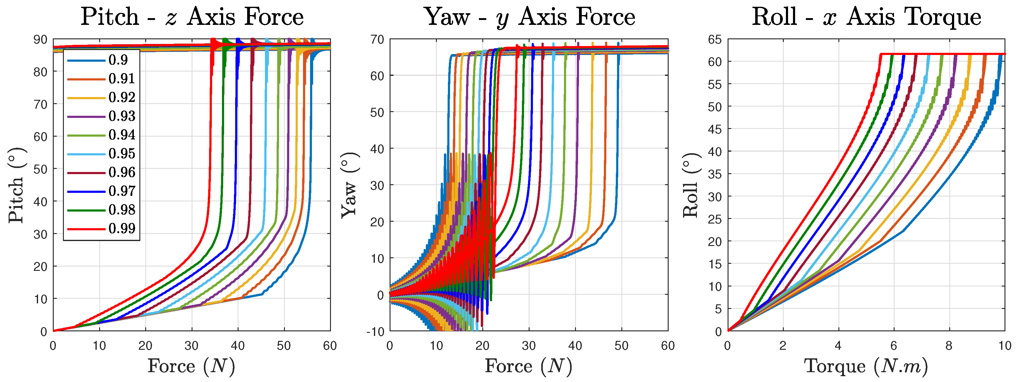
The static load results reveal a greater effect of pretension ratios than natural frequencies, and clearly demonstrate the compliance, resistance, and resilience to external loads in a fully passive manner. To eliminate the interference from other degrees of freedom, constraints relative to each test motion are added—coaxial constraint for roll motion, coplanar constraint for pitch and yaw motions. According to the results illustrated in
Figure 4, the rotation–force/torque curves share a common characteristic that after crossing a smooth region, during which the deformation of the robot assembly gradually increases as the force accumulates, they then enter a rapid growth stage up to the physical limitation of the mechanism. As for the differences, an obvious one is that the yaw and roll motion tests can recover from over-deformed states but not the pitch motion. For the pitch motion, the robot assembly gets into unrecoverable states with the final force of approximately 34.17 N and 55.98 N for 99% and 90% pretension ratios, respectively. For the yaw motion’s case, the values are approximately 27.36 N and 49.27 N, and start to recover at a small load of around 24.22 N and 13.10 N, causing obvious vibrations. Since the physical constraint of the roll motion does not allow it to deform significantly, the recovery curves almost overlap with the deform ones while the former contains slight vibrations at the start of the recovery stage. The forces are approximately 5.52 N and 9.83 N for 99% and 90% pretension ratios. The intermediate pretension ratios’ results separate evenly among these two extremes.
The impact test results are shown in
Figure 5a. The four modules of the robot are numbered 00, 01, 10, and 11, where the left digit represents the robot assembly and the right digit represents the module in the assembly. Module 11 is the one directly facing the ball. Data are taken for 0.2 s starting from the time of contact. The rigid robot’s result is the data set labelled 0 pretension ratio. The maximum acceleration of its four modules are almost the same as expected since it is rigidly articulated. Module 11 of the tensegrity robot bears about two times higher maximum acceleration than the rigid one. In contrast, the rest of the modules of the tensegrity robot hold much lower maximum acceleration at about 1/3. This proves that the tensegrity articulation prevents the impact from passing unattenuated through the whole network of the robot system. It can be interpreted as a sacrifice by the module of impact to protect the rest of the robot from externally inflicted damage. The robot can then decouple the incapacitated assembly and recover from malfunction.
The fall off test results unveil better protection from the robot’s resilience than the impact test. As the robot is not parallel with the ground during fall off, there are two major contact points of which the first is the robot head, module 00, and the second is the robot tail, module 11. In
Figure 5b, the box chart presents the acceleration of each module between the two major collisions. The rigid robot receives very similar maximum acceleration for all modules of approximately 5400 m/s
. Module 00 of the tensegrity robot suffers a similar influence as the rigid one from the collision. However, for the rest of the modules, the effect is greatly mitigated at a scale of approximately 80%. As the pretension ratio increases, the maximum acceleration of module 00 slightly decreases due to smaller tension force held inside the structure. The result shows the improved survivability of the robot during a fall off situation to sustain functionality from such accidents.
4.2. Locomotion Adaptation
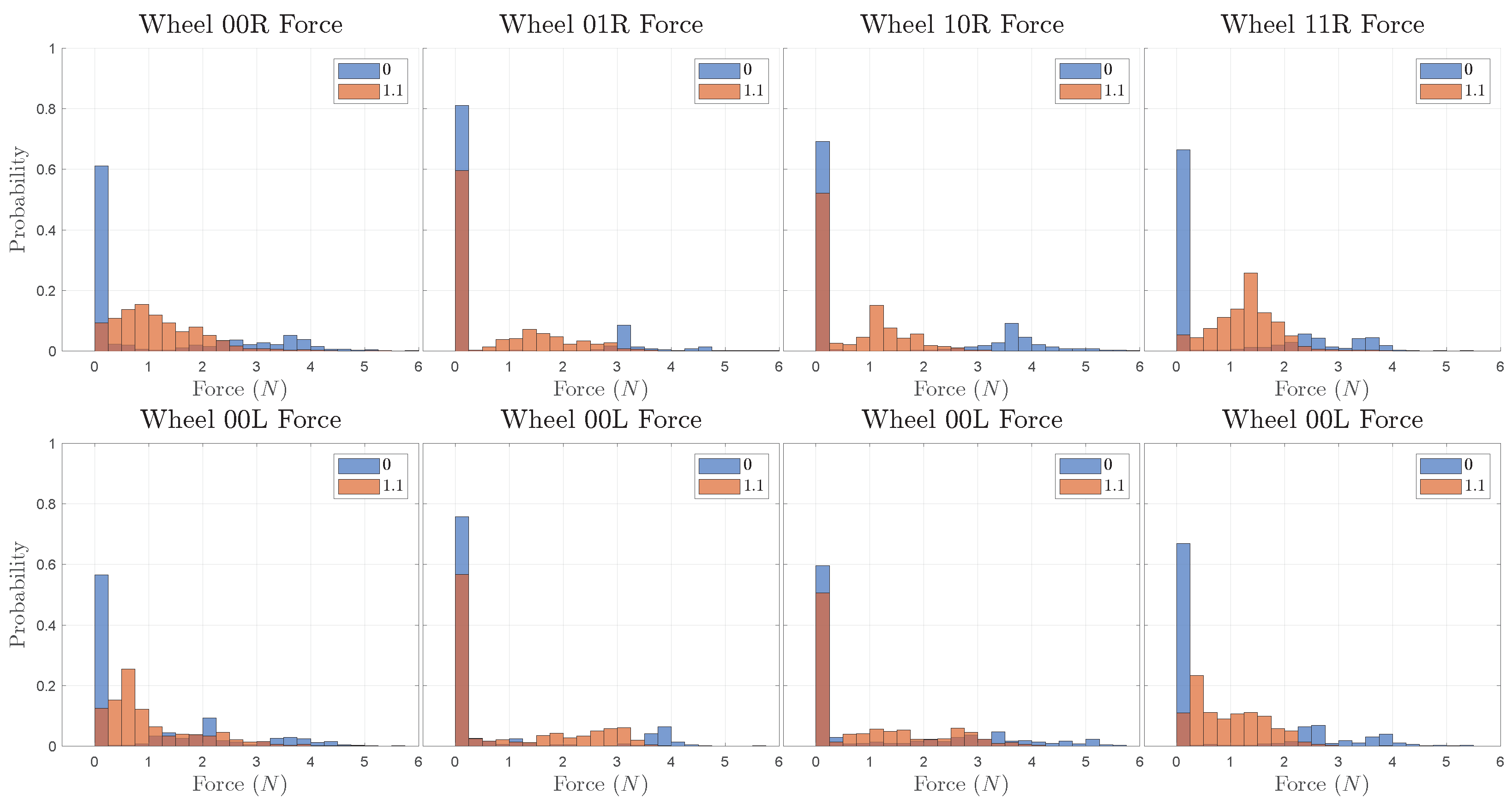
In
Figure 6, the histogram labelled 0 pretension ratio is the contact force of the rigid articulated robot. The active cables of the tensegrity robot are configured with 1.1 times the neutral length. Compared with the tensegrity robot, the rigid robot receives much longer zero force bars, especially for wheels 00 and 11, indicating longer improper contact with the ground. It is clear that the rigid robot’s wheels bear larger average forces when in contact throughout the process, while for the tensegrity robot the distribution is more flat and lies within a lower range. This reflects a better fit to the terrain of the passively operated tensegrity robot.
For active surmounting, testing gives a best result height of 93 mm. Without such active motion, the robot can only cross a step of up to 29 mm in height. For the robot, each robot module body takes a convex space of a 100 mm width cube with a wheel diameter of 90 mm. The wheels are attached 40 mm vertically lower than the centre of gravity of the modules, resulting in the bottom face of the module being 35 mm above a flat ground. It turns out that the robot is able to surmount an obstacle of 68.9% of its total height, 103.3% of its wheel diameter, 265.7% of its ground clearance, or 320.7% of the non-actuated passability.
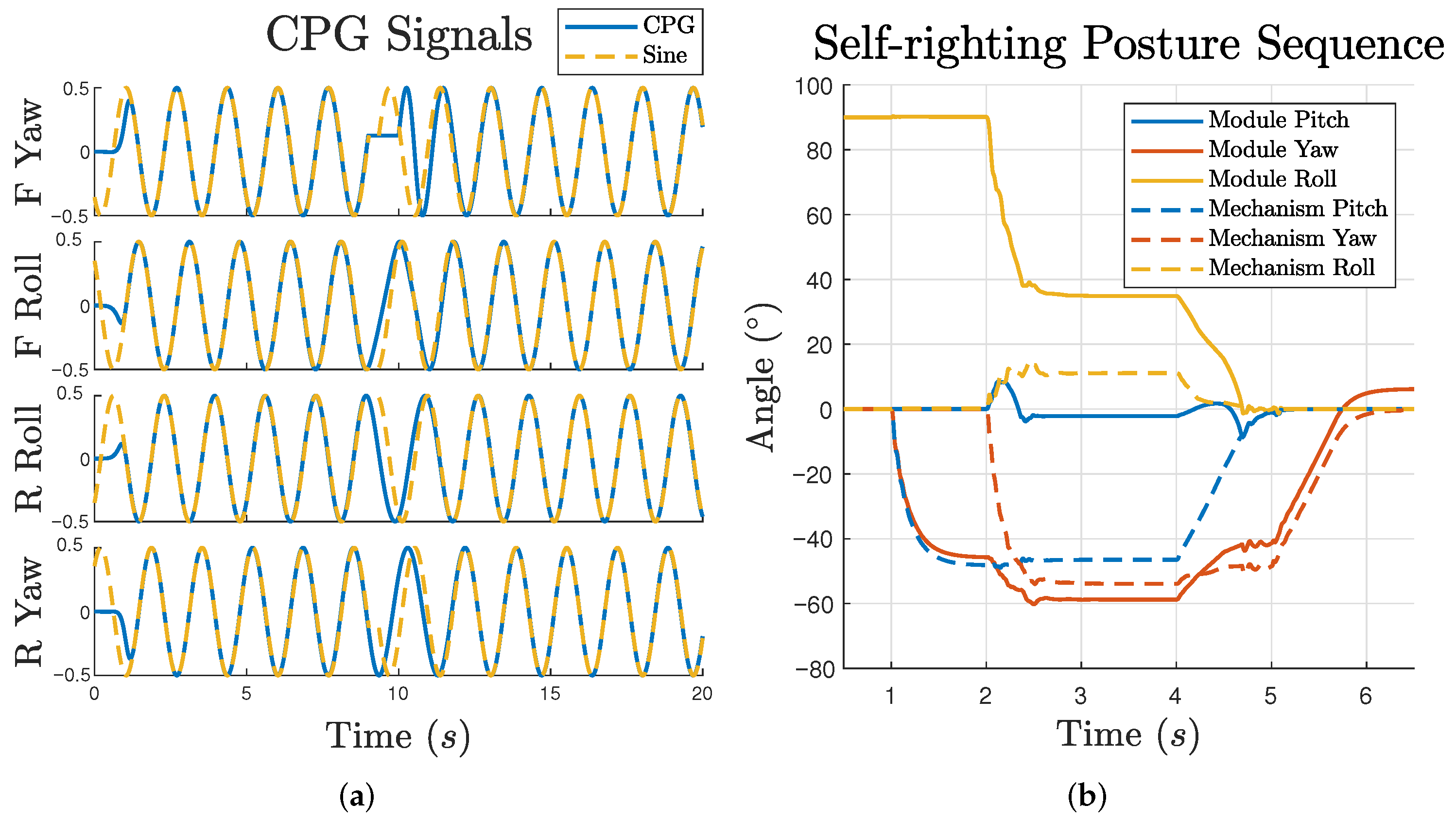
The generated signal of the CPG is plotted in
Figure 7a. For each motion’s signal, it takes about 1 s to smoothly start the oscillation. At 9 s, the front assembly’s yaw motion is purposely stalled for 1 s. As a result, the other three control signals’ frequency is inhibited. After the motion constraint is removed, the oscillators gradually and smoothly restore synchronisation. A reference sinusoidal signal is also plotted for comparison. It is clear that when the synchronisation is established, the CPG output overlaps with the reference.
Self-righting for the two-assembly robot is more difficult than in configurations such as a quadruped as it does not have legs to push off with. The “head” and “tail” are the only contact points available and therefore imitating the behaviour of tortoises to flip over is an efficient solution. To flip by 90, the manoeuvre is completed by sweeping the head and tail by a quarter of a circle. From the perspective of pitch and yaw motion, it will be a full transit from maximum pitch to maximum yaw or vice versa.
The posture of the robot relative to the world is represented by the front module status with solid lines in
Figure 7b. At the beginning, the roll motion is 90
, indicating a rollover state. Following a step by step sequence of the tensegrity mechanism, which is neutral, full pitch, full pitch and yaw, full yaw and neutral, plotted with dashed lines, the roll posture gradually decreases back to zero, representing a successful self-righting.
5. Discussion
Based on the results obtained from the various tests with respect to the structure and locomotion, it is clear that introducing a tensegrity structure with sufficient degrees of freedom endows improved resilience to the wheeled modular robot. Compared with soft robots, the proposed tensegrity robot does not make trade-offs on the important criterion of load capacity by taking the form of conventional cuboid modules. Although it cannot be as flexible as a soft robot design, the results indicate obvious resistance capability in terms of collision and unplanned deformation. Additionally, the ability to adopt both wheeled and legged locomotion modes make it advantageous for soft robots. With regard to rigid robots, it is not difficult to realise equivalent degrees of freedom as the proposed tensegrity robot. However, realising a similar rotational flexibility requires compliant-capable rotational actuators to continuously operate in active mode which is power-hungry. On the other hand, as there is no translational compliance in such systems, and the rotational actuators will be at risk of failure with large impacts.
Tensegrity structures need to retain a pretensioned state to preserve their stability and functionality. Although for some tests the robot gives similar performance for different pretension ratios, the static load results indicate good improvement in weight bearing of about 60% to 80% with pretension changes. This is beneficial for actuation tasks such as the movement of robots’ bodies, legs, and manipulators when overloaded. Compared with existing tensegrity robots that feature a monolithic design, the locomotion of the proposed robot is not limited by the irregular morphology of tensegrity structures. Especially after adopting conventional wheeled locomotion, the efficiency is greatly increased and the robot is no longer affected negatively by the introduction of tensegrity structures. As the robot’s assemblies are independently functional and the detachment/attachment of modules is based on the coupling system, the irregularity of tensegrity will not cause side effects in the reconfiguration of the robot as opposed to monolithic morphologies.
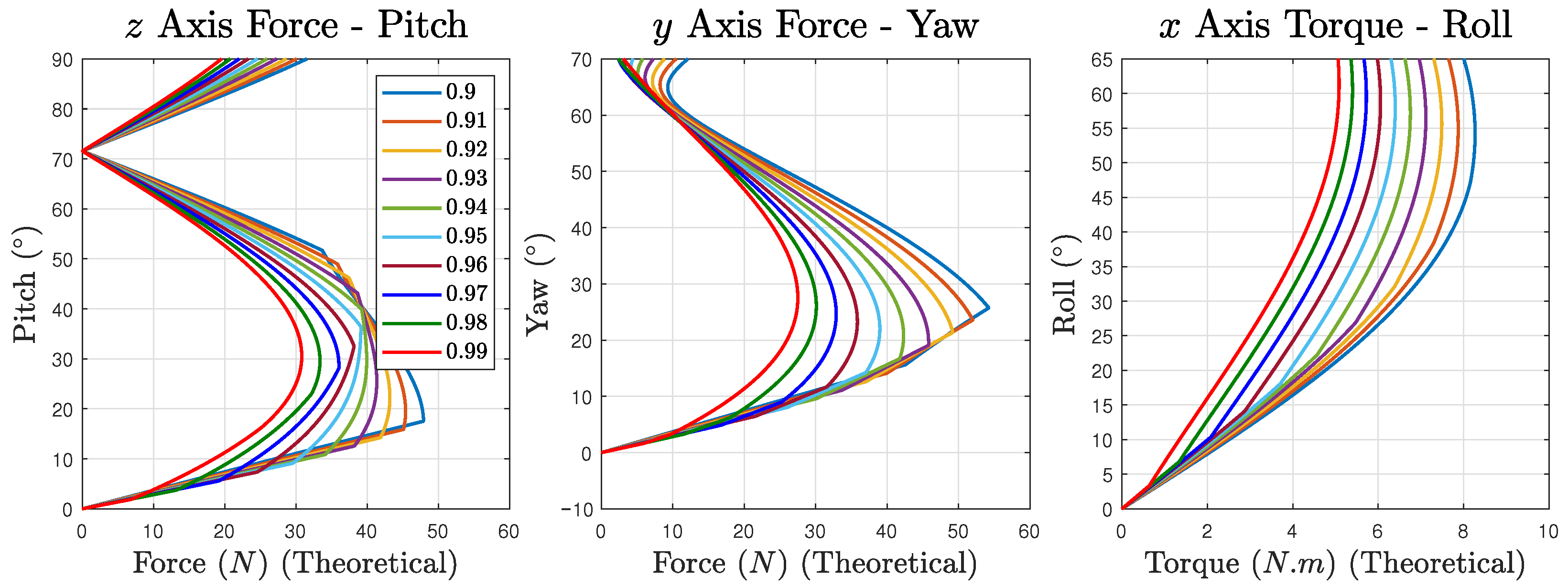
It is worth noting that, from observing the results in
Figure 4, for each motion, there is an almost linear region extending from the start of applying force. This is counter-intuitive as the displacement is not along the cable’s axial direction but rotating around a pivot point with a varying moment arm. To further investigate this, the theoretical force–rotation relationships are calculated, ignoring the small inward displacement of pretension, shown in
Figure 8. It can be seen that there are also linear regions in theoretical plots. This is caused by the cancellation of non-linear force curves among the antagonistic cable pairs. When all the cables are in a tensioned state, the cables that become longer and the cables that become shorter exhibit a similar trend and result in a linear-like force output. Once the cables that become shorter enter a loose status, the generated force will be dominated by the cables becoming longer and therefore the results enter the non-linear region.
It can be observed from
Figure 7b that the mechanism’s pitch and yaw motion curves do not overlap while they actually receive the same target angle. As a sensorless uniform pretension ratio for all actuated cables is used in this paper, the deviation is unavoidable due to flexibility. Fine tuning this is one of the advantages of tensegrity, but the robot requires knowledge of the state. Therefore, one future work direction is to improve the control accuracy of the tensegrity robot by means of either algorithms, feedback, or both.
Although in this paper most of the tests are based on the minimum two-assembly configuration of the robot, its potential should not be limited to this. The three degrees of rotational freedom available actually make each assembly an ideal unit for general purpose actuation tasks inside a comprehensive system. It can be, but is not limited to being, a spine, arm, leg, tail, and manipulator, resulting in morphologies of multiped, snake, or humanoid. These advanced configurations further the capability of the tensegrity robot in harsh environments and form another direction of future work.
6. Conclusions
Resilience is a valuable characteristic of robots designed for tough tasks in challenging environments. It is highly linked to the robots’ overall survivability and life span. In this paper, a tensegrity robot is presented that is resilient in multiple aspects. In the case of external loads and collisions, the robot demonstrates clear compliance and resistance that can protect it from structural failures. With respect to locomotion, different locomotion modes enabled by the agility of the tensegrity mechanism give the robot flexibility on demand to adapt to different terrains. This allows the robot to avoid or recover from malfunctions in harsh environments. The test results reveal that the characteristics of tensegrity structures are well preserved in such designs while additional agility, mobility, and self-reconfigurability are endowed as well.
The conceptual process of how tensegrity structures can be integrated into a robot instead of transforming a whole robot inspires a new approach for designing tensegrity robots. The proposed wheeled tensegrity modular robot offers a good example of fusing comprehensive resilience into previously rigid robots following such a concept.
In future work, the control accuracy of the tensegrity articulation is a key aspect to be considered. This is expected to be addressed by adding force sensors and using force closure algorithms to calculate the theoretical rest lengths at run-time. Orientation information can also be involved to take posture feedback into account and further improve the accuracy. Another direction is to explore the capabilities of different configurations such as quadruped and caterpillar by means of self-reconfiguration.


