1. Introduction
Line-start synchronous motors have gained popularity as an alternative to asynchronous squirrel cage motors, especially in constant speed applications, due to the strict regulations that have been imposed worldwide regarding the efficiency classes of motors that can be used. The asynchronous squirrel cage motors can achieve the IE3 or IE4 efficiency class (in general, efficiency above 89%) with numerous modifications which increase the motor dimensions, material consumption or even imply usage of more expensive materials such as copper bars in the squirrel cage winding or steel laminations with low losses. From 1 July 2021, low-voltage motors up to 1000 kW must meet at least efficiency class IE3 according to a new EU Directive. In a second step, from mid-2023, efficiency class IE4 will become mandatory for the 75–200 kW performance range. Some manufacturers of the motors have answered these challenges and have offered to the market three-phase asynchronous induction motors of the IE4 class [
1,
2]. Researchers have also analyzed various modifications of motor slots such as adding magnet wedges in induction motors with semi-closed slots in order to reduce copper and core losses and increase motor efficiency [
3]. The IE4 efficiency class can be more easily achieved with the line-start synchronous motor (LSSM) as there is no induced current in the rotor winding due to the synchronous speed of rotation, so the rotor copper losses are nullified [
4]. The high power factor at LSSM allows smaller line current and lower copper losses in the stator winding, that in turn increase the efficiency factor; therefore, this type of motor can easily achieve efficiency class IE4 (in general, efficiency above 89%). The combination of the squirrel cage winding and the magnets in the rotor allows for direct starting of the motor with voltage from the mains without the need of the voltage inverters, which are typically needed for starting synchronous motors without squirrel cage winding, as well as synchronization of the motor, provided by the magnets that pull the motor into synchronism. Yet, the proper design of cage winding and the magnets is essential, as the magnets produce the breaking torque that lowers the motor’s starting torque and prolongates the motor starting; however, their improper design results in failure of motor synchronization [
5,
6,
7,
8,
9]. Not only are the magnets responsible for motor operating regimes, starting and steady-state; the stator winding turns also affect the winding resistance, current and the power factor [
10]. Another aspect of motor operation is the material of the squirrel cage winding, which is usually aluminum or copper that affects the motor starting and the temperature distribution [
11]. The temperature distribution also affects the partial demagnetization of the magnets and the operation of the motor, and one such example is analyzed in [
12]. Other authors propose innovative solutions regarding rotor design that include two different types of rotor slots or that focus on the optimization of the rotor slot that allows the best operating characteristics of the motor [
13,
14]. Various optimization techniques have been implemented in the optimization of the magnet thickness, magnet width or the rotor slots at line-start synchronous motors with hybrid magnets (combination of two types of magnet materials) or the line-start synchronous motor with a configuration of magnets with radial flux distribution [
15,
16,
17]. A very small number of works can be found regarding optimization of LSSM with asymmetric permanent magnet array topology. Optimization of the flux barriers of LSSM with asymmetric permanent magnet array topology, which decreases the flux leakage, is found to be a good optimization approach in efficiency optimization, together with the optimization of the dimensions of the rotor slot in [
18]. This paper presents a two-step design modification of LSSM with asymmetric permanent magnet array topology. Authors’ previous research has shown that there are some differences regarding motor operating characteristics and material consumption in correlation with the specific rotor topology of LSSM [
19]. The starting point of the analysis is a three-phase squirrel cage motor type 5AZ 100LA-4, which is a product of the company Rade Končar. The design of the asynchronous motor was modified with a rotor with an asymmetric permanent magnet array topology, thus obtaining the starting model of LSSM (BM). The main constrain of the motor design is the new derived LSSM having the same output power as the asynchronous motor of 2.2 kW. The laminations of the stator and the rotor were obtained from Končar and they remain unchanged in the process of modification of the asynchronous motor into LSSM. The BM, due to the limited space for magnet placement, imposed by the dimensions and shape of rotor slots (Končar design), has a relatively low consumption of permanent magnet material, but poor overloading capability, although the efficiency and the power factor are high. Therefore, as the first step in the design modification was to modify the rotor slots in order to provide more space for magnets and flux barriers. Apart from rotor slot modification and magnet dimensions, no other modifications were made in the design of this second model (M1). The model M1 has good efficiency and an improved power factor and overloading capability but has the relatively high consumption of a permanent magnet material. Therefore, the second step in the design modification was to run the optometric analysis of the M1 model where the outer rotor diameter, magnet thickness and width, along with number of conductors per stator slot, are varied simultaneously within predefined limits and the overload capability, efficiency, power factor and magnet consumption are followed in each combination (iteration of model solving) of those four varied parameters. A total of 25,257 combinations were solved, resulting in model M2, which was found to have the highest efficiency factor, and a good power factor and overloading capability, along with low consumption of permanent magnet material. Optometric analysis is a software module within Ansys Electronics Desktop software; more precisely, it is included in the RMxprt module of the Ansys software and allows arbitrary machine parameters to be varied within defined boundaries while the arbitrary machine characteristics such as efficiency, power factor or overloading capability, depending on the designer’s point of interest, are calculated for each combination of the varied parameters. In this way, the designer can choose the best combination of the motor parameters (for example, outer rotor diameter, number of conductors per slot, magnet thickness and magnet length) that produce the best performance in the machine, for example, highest efficiency, power factor or overloading capability. All motor models are analyzed for the flux density distribution by FEM. The transient characteristics of all motor models were derived, allowing analysis of motor operation at start-up and synchronization. The redesign of the rotor of the asynchronous motor for obtaining LSSM needs careful evaluation and analysis, especially when various rotor topologies are available in order to obtain optimal results regarding motor operation and material consumption.
2. Computer Models for Steady-State and Transient Characteristics
One part of the redesign of the three-phase asynchronous squirrel cage motor into LSSM is to place the magnets inside the rotor, which along with squirrel cage winding, allow starting and synchronization of the motor. The starting point in the analysis was the three-phase squirrel cage motor, a product of Rade Končar, type 5AZ100LA-4, 2.2 kW, 1410 rpm, 5 A, power factor of 0.83, efficiency of 79%. The topology with asymmetric permanent magnet array was chosen for the rotor redesign as the authors’ previous research showed that this topology regarding the analyzed type of the asynchronous motor has some drawbacks, including low overloading capability and relatively low power factor [
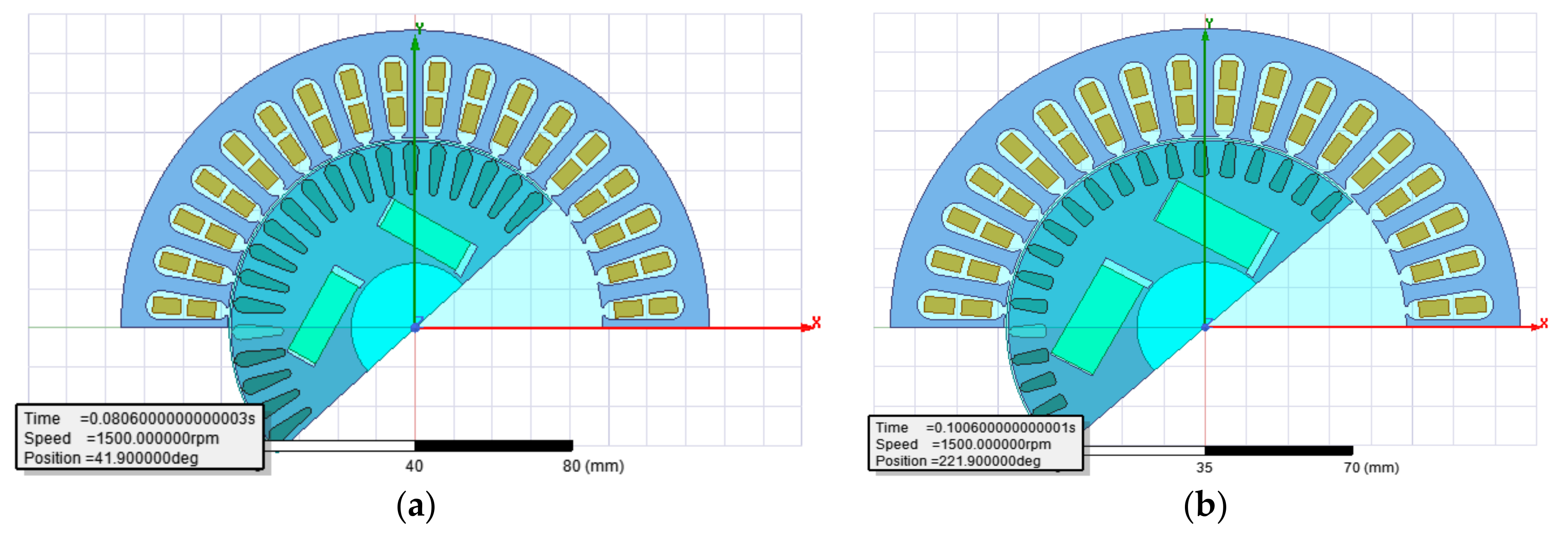
19]. Therefore, it was a challenging task to improve the overloading capability, power factor and efficiency with minimum consumption of permanent magnet material while keeping the same power output of 2.2 kW, as it is in the asynchronous motor. The LSSM with the asymmetric permanent magnet array topology is presented in
Figure 1a.
Firstly, the computer model of the asynchronous motor for calculating motor parameters and steady-state characteristics was modeled. This model will be referred to as AM. Since all the further computer models of the line-start synchronous motor will be derived from this model (AM), it was necessary to verify its accuracy by comparing data obtained from AM with the catalogue data from the producer of the motor [
20]. This comparison and the obtained results are presented in
Table 1. From the results presented in
Table 1, it can be concluded that the AM model is sufficiently accurate and it can be further modified into line-start synchronous motor with asymmetric permanent magnet array rotor topology. The BM model of line-start synchronous motor is derived from three-phase asynchronous squirrel cage motor 5AZ 100LA-4, a product of Končar, without any alteration of the stator dimensions or the geometry of the stator and rotor slots [
20]. The BM model is derived for the same output power of 2.2 kW as it is in the asynchronous motor. The model is designed to obtain the highest possible efficiency and output power with minimum consumption of permanent magnet material. Therefore, in the asynchronous motor (AM), whose data are presented in
Table 1, the rotor is modified by decreasing its diameter, i.e., the air gap length is increased from 0.3 mm to 1 mm along with adding the flux barriers and permanent magnets in asymmetric array topology. The increase in air gap was due to the modification of asynchronous motor in line-start synchronous motor in order to maintain the good overloading capability of the line-start synchronous motor. The AM has an overload capability (maximum torque versus nominal torque) of 2.6. The dimensions of the magnets, height and thickness, were calculated for obtaining the highest efficiency and power factor along with a good overloading capability of the motor. This first model in the analysis of the line-start synchronous motor derived from the asynchronous motor, without the changes of the dimensions of the stator, slots of the rotor and the stator, is referred to as the BM model. This BM model will be the starting point with which the modified and optimized models will be compared.
The analytical calculations for this model were performed in Ansys software together with the calculation of steady-state characteristics. Therefore, it was necessary to input the exact dimensions of the cross-section of the motor along with the characteristics of all materials applicable in the motor design. The results obtained from the BM regarding parameters and operating characteristics showed that although BM has low consumption of permanent magnet material, it has little overloading capability. The consumption of permanent magnet material is limited due to available space for the placement of magnets in the rotor and this affects the overloading capability of the motor. This is due to the geometry of the rotor slot (
Figure 1a) which was taken over from the asynchronous motor. Therefore, the first step in improving the model of the line-start synchronous motor with asymmetric permanent magnet array rotor topology was to modify the rotor slots, keeping almost the same cross-section of the slot with a modification in its geometry that allows more space in the rotor for the magnets to be placed. This second model will be referred to as M1 model. The modification of the slot in M1 in comparison to BM is presented in
Figure 1b. In addition to rotor slot modification in M1, all other dimensions of the motor, features of the both windings, and material properties remain unchanged. From the results obtained from model M1, it was observed that this model had significantly larger consumption of permanent magnet material than B1, although the overloading capability was improved. The second step in model improvement was to run the optometric analysis of the model M1 where four parameters are chosen to be varied simultaneously within predefined ranges: the outer rotor diameter (ORD), magnet thickness (MT), magnet width (MW) and number of conductors per stator slot (CPS). The motor variables and their ranges of variation are presented in
Table 2.
The ranges of variation of magnet geometry were defined on the base of the available space in the rotor. The computer program calculates the slot fill factor for the stator slots. The program is set to the maximum slot fill factor of 75%. When the limit is reached, the program adjusts the wire diameter in order not to succeed the limit of the slot fill factor. The rotor’s outer diameter is varied, taking into consideration the inner stator diameter and the air gap length of the asynchronous motor. The length of the air gap of the asynchronous motor is 0.3 mm. The overloading capability was one of the issues that needed to be improved in the optimized model of line start synchronous motor. The larger air gap contributes to the increased overloading capability while simultaneously worsening the efficiency factor and power factor. Another design aspect is the dimension of the magnets. The increased magnet thickness has a positive effect on the increase in the efficiency, power factor and the overloading capability of the motor; however, it decreases the starting torque. The increase in the magnet width decreases the efficiency but increases the overloading capability and the power of the motor. From the above, it is obvious that various selected parameters have a contradictory effect on motor operating characteristics and there is no straightforward solution which combines the four above-mentioned varied parameters and produces the best operating characteristics of the motor at steady-state operation as well as at transient regimes. Therefore, by optometric analysis, each combination of motor variables (25,257 combinations) is implemented in motor analytical model, modeled in Ansys software and, by following the output results with respect to motor operating characteristics, the most favorable analytical motor model can be selected for further analysis by the aid of numerical and dynamic models. A total of 25,257 model combinations with the varied parameters were solved. Among all 25,257 models, the three most favorable solutions were chosen in terms of the efficiency, the power factor, the overloading capability and the consumption of permanent magnet material. These models will be referred to as models M2, M3 and M4. In terms of the highest efficiency factor and the smallest permanent magnet material consumption, model M2 has the best results; therefore, this model is further analyzed with numerical methods and applied into the simulation circuits of the dynamic models. The basic criteria for choosing the models M2 to M4 (obtained by optometric analysis) was to have an overloading capability above 2.2, efficiency above 95.9 and power factor above 0.9. Model M1 is derived from model BM without any optometric analysis, only by redesigning the rotor slots, in order for more magnet material to be placed, so as to obtain a larger overloading capability than the BM model. This was achieved, either because the M1 model has a maximum output power of 4326 W compared to 3572 W of the BM model, or because the M1 model has an increased overloading capability of 1.9 compared to the BM model which has 1.6. Another aspect of motor design is the permanent demagnetization of magnets due to reverse fields exceeding the value of H
d, a point at which the magnetic vector polarization vector M collapses. The corresponding value of flux density is B
d. The demagnetization of magnets has been checked according to [
21]:
where
Idgmrm is the maximum permitted value of steady-state stator current for normal steady-state operation before demagnetization (A).
p is the number of stator poles,
Kw1 is the winding factor,
Nc number of turns per phase of stator winding,
hm is the magnet thickness in radial direction in meters,
g is the air gap length in meters and
Br is the residual flux density in Tesla at the operating temperature of the magnet. In all motor models, the SmCo28 magnets are used with remanent flux density of 1.07 T and coercitivity of 820,000 A/m. The analysis of demagnetization of the magnets is especially important during transient regimes, i.e., at motor starting and synchronization. At asynchronous starting, currents with a maximum value up to several times greater than the amplitude of the rated motor current can flow in the stator winding. Supply voltage, the magnetic flux generated by magnets, the moment of inertia of rotating masses and load torque affect the start-up course and the amplitude of the inrush current. The impact of the magnetomotive force caused by the armature interaction related to the amplitude of the stator currents may cause partial demagnetization of the permanent magnets located in the motor [
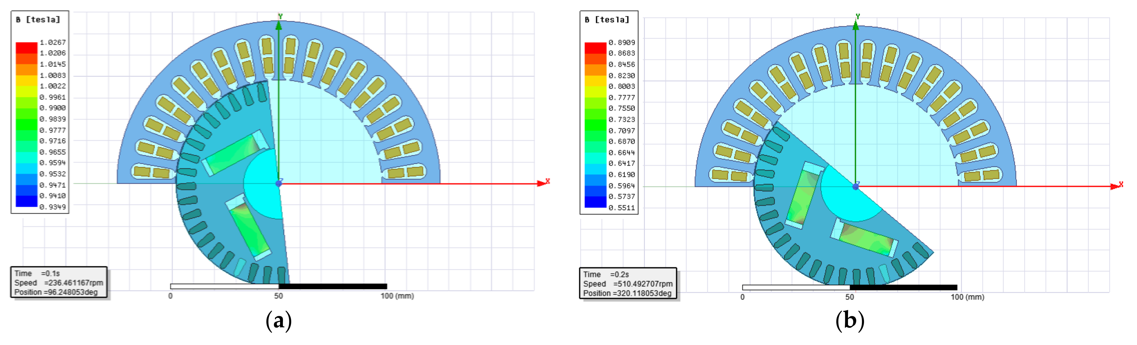
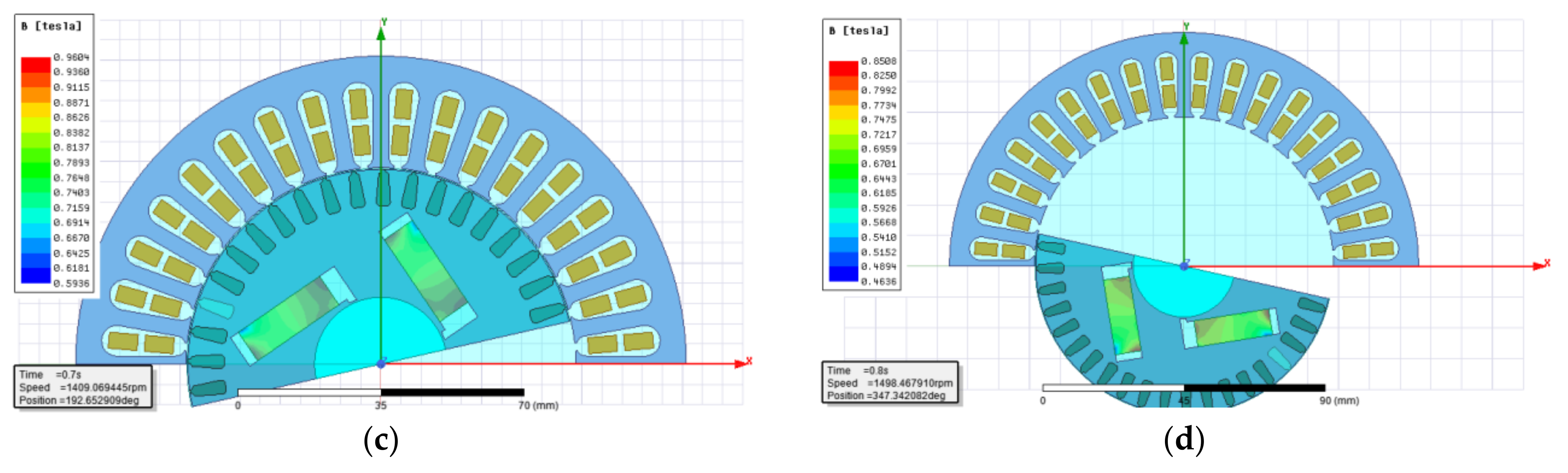
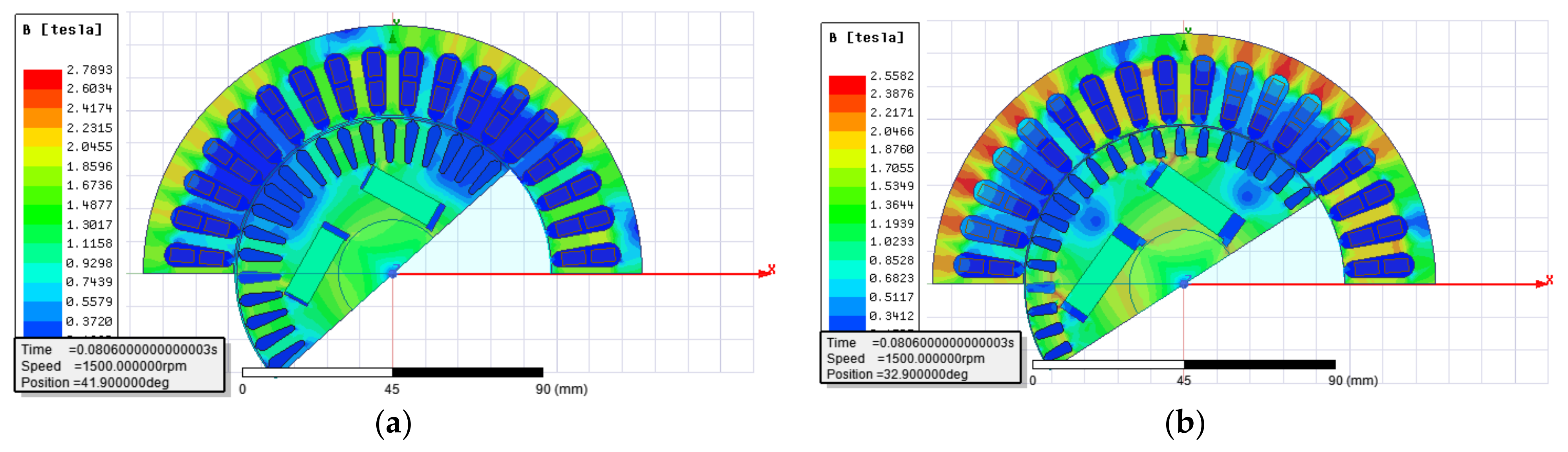
12]. Due to irreversible demagnetization of the magnets, the main magnetic flux is irreversibly reduced and consequently so is the motor torque. The demagnetization of the magnets at motor starting and in the vicinity of synchronization speed is analyzed by FEM. The flux density at magnets at various speeds during acceleration of model M2 is presented in
Figure 2 for a load torque of 14 Nm and a moment of inertia of 0.37 kgm
2. The magnitude of the magnetic field for the same operating regimes from
Figure 2 is presented in
Figure 3. From the presented results in
Figure 2 and
Figure 3 and for the type of magnets used, the partial demagnetization could occur in tiny areas of magnet edges in the vicinity of synchronous speed. In other analyzed operating points during motor acceleration, the demagnetization of magnets should not occur.
The numerical model allows magnetic flux density distribution to be calculated in the motor cross-section by the aid of Finite Elements Method (FEM) thus allowing parts of the magnetic core with high flux density to be detected [
22,
23,
24]. Another aspect of analysis of the models is the transient characteristics where the motor behavior in transient regimes such as start-up can be analyzed [
25,
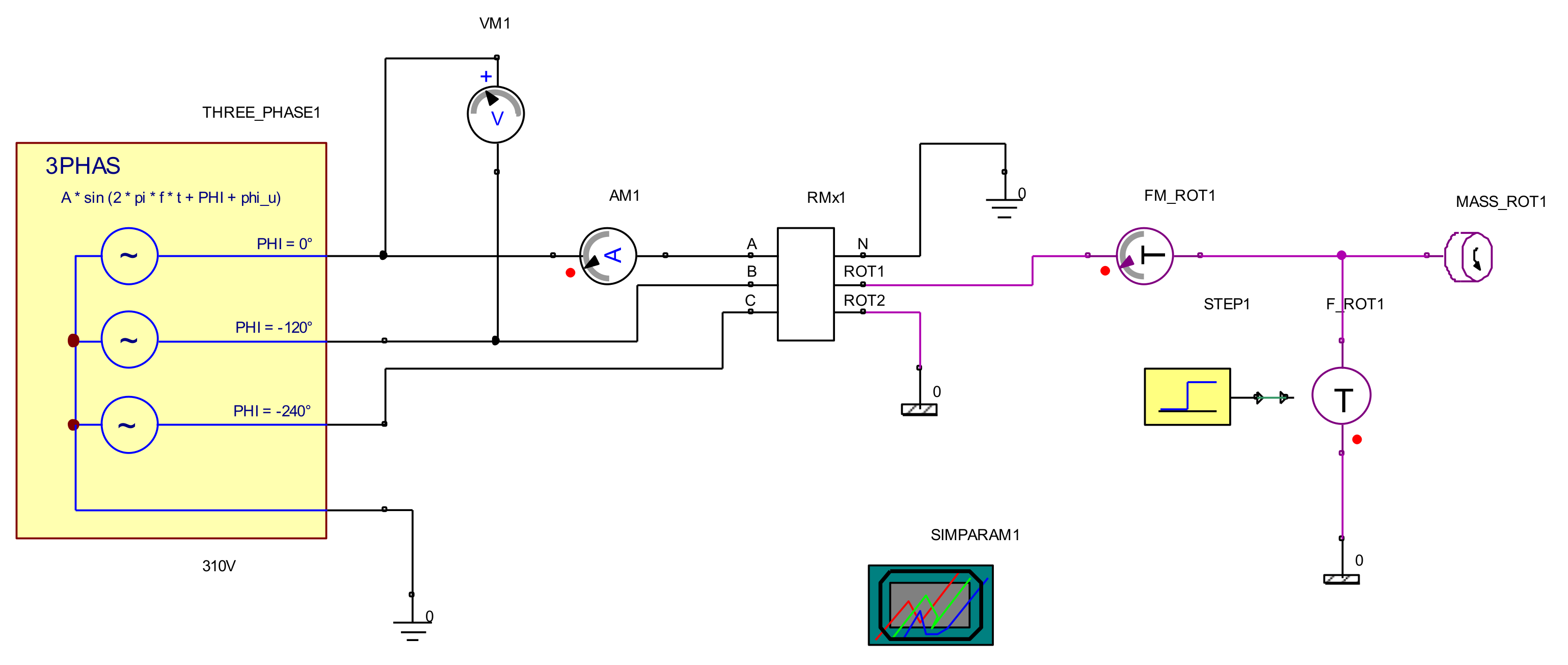
26]. The M2 model is implemented in the dynamic model in order to obtain transient characteristics of speed, current and torque at motor acceleration and at steady-state operation (operation with synchronous speed). The last part of the analysis is necessary due to the specific construction of line-start synchronous motor. Namely, the squirrel cage winding contributes to the motor starting directly with the voltage from the three phase supply, while permanent magnets pull the motor into synchronism. The magnets generate the breaking torque that can worsen the motor starting conditions. On the other hand, their improper design may result in the failure of motor synchronization. The dynamic models are designed for BM and M2 when the motor is accelerated with various loads and load inertia. The motor acceleration and synchronization is analyzed and adequate conclusions are derived. The motor dynamic model is presented in
Figure 4. The dynamic model of the motor that allows calculation of transient characteristics is derived in Ansys Simplorer. The software has blocks that allow for modeling the symmetrical three-phase power supply. Additionally, it allows the model of the motor derived in RMxprt module of Ansys Electronic Desktop to be imported via a dynamic link. The motor output is linked to the load torque and inertia. The more detailed explanation how to derive drive design can be found in [
27]. The computational time of the drive system with various loads and moments of inertia takes no more than couple of minutes depending of the set time for simulation and the set maximum and minimum time steps.
The basic equation behind the dynamic model of the motor in
d-q reference frame is [
28]:
where
s is the slip defined as:
The coupling between the electrical system and the mechanical system is represented by the torque equation and the mechanical equation. The electromagnetic torque
Tel developed by the motor can be expressed as:
The motor torque is balanced by the mechanical shaft torque
Tload and the dynamic torque caused by the total inertia
J [
29].
Motor parameters are calculated in RMxprt module of Ansys Electronics Desktop software. This model of the motor from RMxprt module with all data and calculated parameters is linked, i.e., imported in the dynamic model which is modeled in the software module Ansys Simplorer. The motor parameters for the model M2 are presented in
Table 3.
The description of methodology for obtaining the numerous parameters of line-start synchronous motor can be found in [
30]. Due to extent of the mathematical model, it is not presented here. Further details can be found in [
30,
31].
4. Discussion
Obtaining the optimal motor design is not always a straightforward solution, considering that there are many design parameters that have an impact on motor operating characteristics. Improving one operating characteristic may result in deterioration of another. Therefore, four motor parameters (CPS, ORD, MW and MT) that have an impact on motor transient and steady-state characteristics are varied within the prescribed limits, which are determined by designers’ experience in order to find the best combination of these four variables to allow obtaining a high efficiency, power factor, and overloading capability along with a cost effective solution regarding material consumption. The line-start synchronous motor with interior asymmetric permanent magnet array is derived from a three-phase squirrel cage motor based on data and the steel laminations from the producer Rade Končar, i.e., the BM model. The BM model is derived from the model of the asynchronous motor (AM) by adding the permanent magnets and flux barriers inside the rotor. Since the overloading capability of the synchronous motor should have a satisfactory value, the air gap length is increased when modifying the AM into BM. In the BM model, the number of conductors per slot was decreased compared to the AM model, which resulted in a lower stator current and considerably lower copper losses in the stator winding. The decrease in the current at BM is also a result of significantly improved power factor at synchronous motor (BM) compared to the asynchronous motor AM. The rotor copper losses at the rated load operation are not present in the BM model of line-start synchronous motor due to its principle of operation. No current is induced at synchronous speed of the motor in the rotor winding; therefore, no copper losses are present in the rotor winding of the synchronous motor. The detailed breakdown of all losses of the both models of the motor, the asynchronous (AM) and the synchronous (BM) are presented in
Table 1 and
Table 4. The above-mentioned modifications of the BM model compared to AM model resulted in a significant increase in the efficiency from 78.4% at AM to 94.3 at BM. The first modification of the motor design which involved only a redesign of the rotor slots were in model M1. The reason for redesigning the rotor slots was to provide more space for magnets in the rotor since the original BM model had a low overloading capability of 1.6 and a maximum output power of 3572 W. By modifying the rotor slots, the magnet thickness and width can be increased, which in turn provides the larger overloading capability of the model of 4326 W or 1.9. The increase in the overloading capability is due to the increased weight of magnet material; consequently, the costs of production are increased as well. No significant improvement of efficiency factor can be observed in the M1 model, compared to the BM model, although the power factor is improved, the line current is decreased and so are the copper losses (
Table 4). The magnet thickness and width along with outer rotor diameter, i.e., the air gap length and the number of conductors per slot, are selected as parameters to be varied in the optometric analysis, which resulted in the models M2, M3 and M4. In terms of the overloading capability, efficiency and power factor, the M4 model has the best operating characteristics of efficiency 96.1%, power factor of 0.93 and overloading capability of 2.8, i.e., a maximum output power of 6158 W. The consumption of permanent magnet material is considerable; therefore, the M4 is not the most cost effective solution in terms of material consumption. The models M2 and M3 have similar operating characteristics (efficiency 96 and 95.9, power factor 0.9 and 0.94, and maximum output power of 4929 and 4837, respectively). In terms of permanent magnet consumption, M2 has smaller consumption, 0.69 kg versus 0.8 kg at M3. The M2 model is chosen for further analysis as it has the better efficiency, overloading capability and smaller permanent magnet consumption than the M3 model. M2 also has the smaller air gap, fewer conductors per slot than M1 and, consequently, lower copper losses and greater efficiency than M1. Lower copper losses in the M2 are also a result of the decreased air gap in the M2 model compared to the M1 model, which resulted in the improved power factor; consequently, the current is decreased and, finally, the copper losses are decreased. The fewer conductors per slot, combined with the smaller air gap length, contributed to the lower stator winding resistance, greater power factor, lower current, smaller copper losses and greater efficiency of the M2 model compared to the M1 model. The M2 model also has the modified rotor slot compared to the M1 model. This modification provides more space for magnets in the rotor, which contributes to the greater power factor, lower motor current, smaller copper losses and better efficiency of the M2 model. The modification of the rotor slot is also important for the overloading capability of the motor. The increase in the amount of the magnet material (more available space for magnets in the rotor) increases the overloading capability of this type of line-start synchronous motor. The motor optimization and modification should be evaluated in terms of complete spectrum of operating characteristics, not just in terms of the efficiency or the power factor. Therefore, the rotor slot modification is important for the overloading capability of the motor and this can be clearly observed from the presented data of the M4 model in
Table 4. All motor models are calculated with the same steel laminations. The type of steel in the lamination does not have such a drastic impact on the efficiency. The authors’ preliminary analysis showed that various types of steel affect the efficiency by no more than two to three percent (depending of the type of the steel and its specific losses). Further research can be extended with the detailed analysis of the impact of the type of the steel laminations and their specific losses on the motor efficiency. The impact of CPS on motor efficiency is presented in
Figure 9. The program adjusts the wire diameter according to the CPS in order not to exceed the limit of slot fill factor of 75%. The wire diameter has an impact on the stator winding resistance and, consequently, on the line current, the copper losses and the efficiency. The impact of CPS on the stator winding resistance, line current, copper losses and total losses is presented in
Figure 20.
The impact of CPS on the stator winding phase resistance is significant and it contributes greatly to the copper losses and, consequently, to the total losses and the efficiency factor (
Figure 20c). The impact of CPS on line current is not as pronounced as it is on the winding resistance (
Figure 20b). The cooper losses which are significant part of the motor total losses are determined by the impact of CPS on stator winding resistance. The decrease of the number of CPS has a positive impact on the decrease of winding resistance and has a negative impact on the stator current since the current increases and consequently the copper losses as well. Yet, the decrease in the winding resistance and its contribution to the copper losses and consequently to the total losses is more pronounced than the impact of the increase of the line current on the copper losses and consequently to the total losses. Therefore, the decrease in the number of CPS has a positive impact on the improvement of total losses and results in an increase in the efficiency factor. This statement is verified by the data presented in
Table 4 (model M2).
Figure 20 should support presented result of impact of CPS on the efficiency (
Figure 9a). The smaller number of CPS has a positive impact on the increase of efficiency but simultaneously decreases the power factor. Additionally, the smaller number of CPS contributes to the larger starting torque and the overloading capability of the motor. The CPS has a significant impact on all evaluated motor operating characteristics (efficiency, power factor, stating torque and maximum output power). The impact of ORD is more pronounced on the efficiency and the power factor, while it is not the case with the starting torque and the overloading capability (
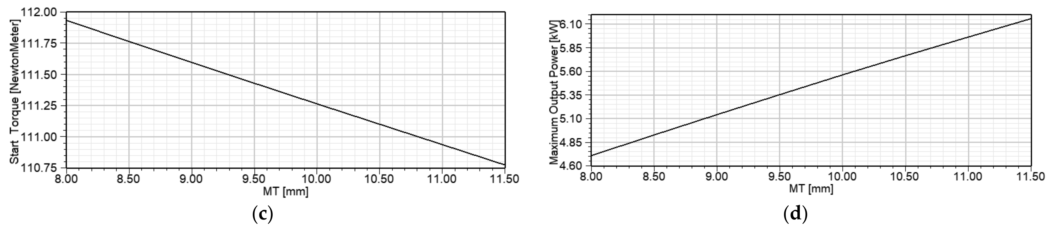
Figure 10). The larger air gap or the smaller ORD decreases the efficiency and the power factor. MW has no significant impact on the efficiency, the power factor, the starting torque and the overloading capability (
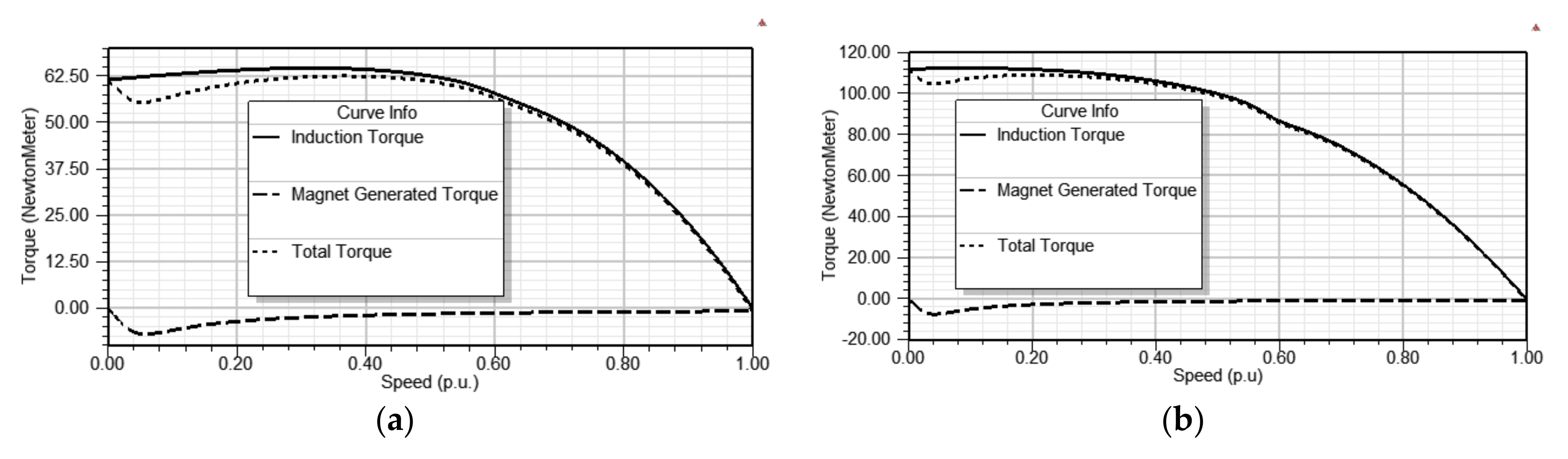
Figure 11). On the other hand, MT has the greatest impact on motor overloading capability and power factor. The thicker the magnets are, the greater the power factor and the overloading capability are (
Figure 12). From all four varied parameters, CPS has the biggest impact on all four analyzed operating characteristics, efficiency, power factor, starting torque and overloading capability. ORD, i.e., air gap length, has a significant impact only on efficiency and the power factor. MW is not a critical parameter regarding analyzed operating characteristics but MT has crucial impact on the overloading capability and the power factor. The impact of varied parameter CPS, ORD, MT and MW on motor efficiency can be observed from
Figure 9a,
Figure 10a,
Figure 11a and
Figure 12a). From the data presented in the above-mentioned figures, it can be concluded that variation of CPS had the biggest impact on the percentage of motor efficiency, i.e., the variation of CPS from 65 to 108 impacts the change of efficiency from 93.5 to 96.2%. The change of air gap length has also a significant impact on efficiency, which varies from 94.9% to 96.1% with the increase in the ORD, or with the decrease in the air gap length from 1 mm to 0.5 mm. The impact of magnet width on motor efficiency is not so pronounced. The efficiency percentage varies very little with the variation of magnet width, i.e., from 96.04 % to 96.07 %. The impact of magnet thickness on efficiency is more significant, i.e., it increases from 96.04% to 96.14% with the increase in the magnet thickness. From the above, it is evident that various parameters have different impacts on various motor operating characteristics; therefore, it is necessary to employ computational techniques, such is the case with optometric analysis, which involve fast and accurate calculation of various motor models that allow for the determination of optimum values of analyzed motor parameters which produce the best operating characteristics in terms of complete specter of them, combined with the most cost effective solutions regarding material consumption.
The M2 model has been chosen as an optimal solution regarding operating characteristics and the permanent magnet material consumption. Both models BM and M2 are modeled with FEM for the flux density distributions. According to
Figure 13, models BM and M2 have higher flux density in the stator yoke. This can be improved by redesigning the stator, i.e., increasing the stator outer diameter. In this paper, modifications of the motor are performed on the basis of a three-phase squirrel cage motor, a product of Končar, without any changes in the motor outer dimensions.
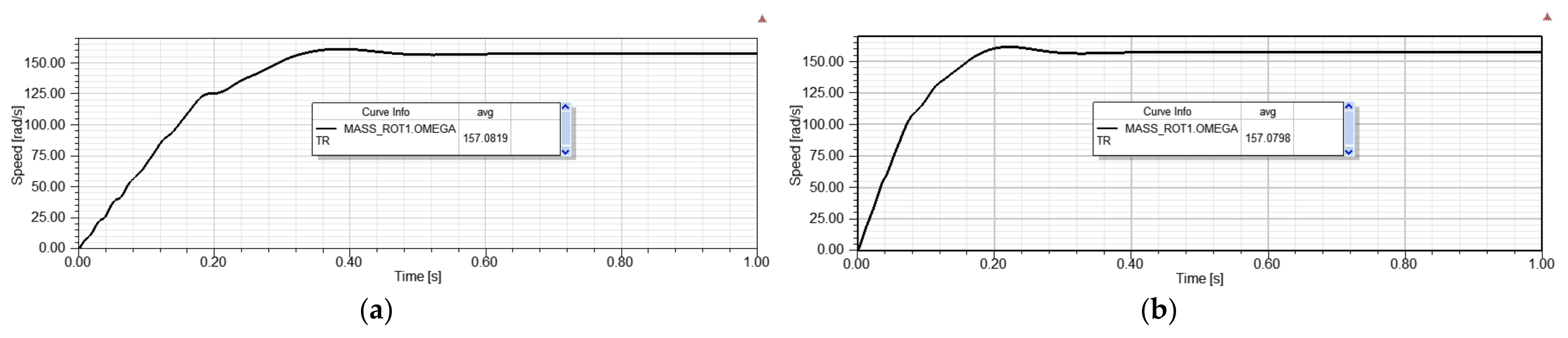
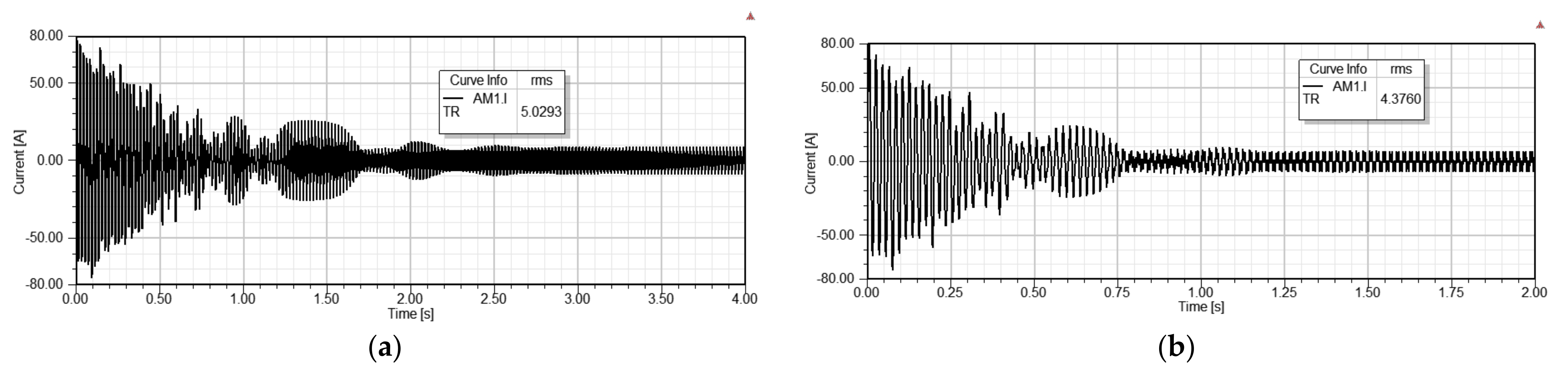
The line-start synchronous motor should successfully start and accelerate up to the synchronous speed when it is plugged in the three-phase voltage. The successful starting, acceleration and synchronization are determined by the rotor cage winding and the permanent magnets. Their proper design is vital for the successful operation of the motor. The transient characteristics of speed, current and torque, presented in
Figure 14,
Figure 15 and
Figure 16, allow analysis of the acceleration and synchronous operation of both models BM and M2. Both models are accelerated with the rated load of 14 Nm coupled to the motor shaft. The M2 model has higher starting torque and lower acceleration time than the BM model. Both motors reach the synchronous speed and maintain the synchronous operation. After the acceleration has finished, the motor torque reaches the value of 14 Nm for both models. This can be expected as they are loaded with the rated torque of 14 Nm. Similar observations can be made for the motor current which reaches the rated load current after the motor has accelerated. The analysis is extended by loading the M2 model with different loads and load inertia, i.e., 10 Nm and load inertia of 0.24 kgm
2 and 14 Nm and load inertia of 0.37 kgm
2. In both cases, the motor synchronizes and maintains the synchronism.
Table 7 presents the comparison between results obtained in
Table 4 from computer models for calculation of motor parameters and characteristics and the results of speed, torque and current from the transient characteristics (
Figure 14,
Figure 15 and
Figure 16). The average values of speed and torque are calculated by the dynamical model for the last time interval of characteristics and presented in
Figure 14 and
Figure 15. The rms value of current for the last time interval of current characteristic is presented in
Figure 16.
From the results presented in
Figure 16, it can be concluded that there is a significant distortion of current waveform due to the presence of harmonics. Harmonics are often present in the current of line-start synchronous motor as a result of permanent magnets inside the rotor. The current higher harmonics cause absorption of distortion power and increase in stray load losses [
32]. The rms value of current of the dynamic model has higher value than the analytically calculated current (
Table 3) due to presence of harmonics. These harmonics cause the heating effects in the conductors, as the eddy losses are proportional to the square of the frequency. Moreover, harmonics can cause interference in the protection systems, communication systems, and signaling circuits due to electromagnetic induction [
33]. The harmonics contribute also to the increased noise and vibrations during motor operation. To mitigate the problem with harmonics some authors propose the usage of filters or modification of rotor teeth width [
33,
34].
From the results presented in
Table 7, it can be concluded that computer model for analytical calculation of parameters and characteristics and the dynamic model have satisfactory similarity of results of speed, current and torque. In addition to the verification of the motor dynamic regimes, the presented results in
Table 6 should verify the accuracy of both models, the computer model for calculating parameters, the steady-state characteristics and the dynamic model.
The M2 model achieves high efficiency and a very good power factor combined with good overloading capabilities, considerably higher than the efficiency of motor for the same power rating found in [
4]. Yet, the derived model is theoretical, based on computer simulations. The proposed model should be verified by the prototype and experimental measurements. It can be expected that the manufactured model will have lower efficiency and power factor. The model is subject to manufacturing limitations such as achieving a good slot fill factor, manufacturing tolerances regarding length of the air gap, built-in material in the motor construction and accurate measurement of frictional and windage losses.
5. Conclusions
The line-start synchronous motor has drawn the attention of scientists and industry professionals as a possible replacement of three-phase squirrel cage induction motors, especially in constant speed applications, due to their high efficiency and good power factor. The strict regulations of the EU market regarding usage of IE3 efficiency class of motors (that can be achieved with three-phase squirrel cage motors with numerous modifications that require more material with high quality and low losses) increases the interest for these line-start synchronous motors, which can easily achieve IE4 efficiency class. Among the line-start synchronous motors, there are various topologies which require different designs of the rotors and produce different motor operating characteristics. The authors have chosen to analyze the line-start synchronous motor with an interior permanent magnet asymmetric array topology as this configuration needs more detailed analysis and modification of rotor design, due to the availability of the space in the rotor to place magnets with sufficient dimensions, in order to achieve good efficiency, power factor and overloading capability of the motor. Starting from the three-phase squirrel cage motor of 2.2 kW, the first model (BM) is obtained by placing the magnets inside the rotor without any other modifications in the motor. The obtained BM model has high efficiency and power factor but relatively low overloading capability. The second model (M1) with modified rotor slots and magnet dimensions has high efficiency and power factor, improved overloading capability of the motor but relatively high consumption of permanent magnet material. Therefore, more modifications of motor design were needed that included modification of the air gap length, magnet width and thickness and the number of the conductors per slot. In order to determine the best combination of these four parameters that produce the high power factor and efficiency, with good overloading capability and low consumption of permanent magnet material, the optometric analysis was run and more than 25,257 combinations were solved. This analysis is a useful tool as the increase in one parameter can improve one operating characteristic and worsen the other, and vice versa. When four different parameters are varied within certain boundaries simultaneously, without optometric analysis, it is very difficult to determine which value each of these parameters should have that will produce a model of the motor which will satisfy four various operating characteristics regarding optimal or improved operation in comparison to the starting model. Among these numerous combinations, the M2 model, with a sufficiently high power factor, efficiency and overloading capability (higher efficiency and overloading factor than models BM and M1) and considerably lower consumption of permanent magnet material is chosen as the optimal solution. The impact of each varied parameter on motor operating characteristics is analyzed, providing detailed insight into which design guidelines should be followed for obtaining satisfactory design of the motor. The chosen model (M2) was analyzed with FEM for the magnetic flux density distribution and with dynamic models for obtaining the transient characteristics. The M2 model has some areas of stator yoke with high flux density which can be improved by increasing the stator diameter, subject to further research. The dynamic behavior of M2 is satisfactory since the motor reaches the synchronous speed and continues with stable operation.
The careful analysis of each parameter and its impact on motor operating characteristics can significantly improve the motor operation, leading to the cost effective design of the motor. The proposed model is based on computer analysis and simulations. Its prototyping is highly affected by various manufacturing details such as obtaining a good slot fill factor or vibrations and noise as a result of the air gap length, which can have a significant impact on the final outcomes of this analysis.


