Abstract
A traveling-wave tube (TWT) with a sheet electron beam and staggered double-grating slow-wave structure (SWS) is a promising high-power, wideband terahertz amplifier. In such tubes, electron-optical systems (EOSs) with a converging sheet beam are mostly used, which allow a reduction of the cathode load, increase the lifetime, and enable operation in a continuous-wave (CW) mode. This paper presents the results of a 3D particle-in-cell (PIC) simulation of the 0.22 THz TWT driven with a converged sheet beam, which is compressed to less than 100 μm thickness in the EOS with a magnetically shielded cathode. The beam with high compression has a significant transversal velocity spread and essentially non-uniform current density distribution over the cross-section. These factors significantly affect the beam–wave interaction. We compare the performance of the TWT driven by the compressed sheet beam and by an idealized initially rectilinear beam without any velocity spread.
1. Introduction
Modern wireless high-data-rate communications require high-power reliable radiation sources operating at sub-THz frequencies (above 100 GHz) [1]. Vacuum electron devices (VED) such as TWT power amplifiers offer a solution since they combine high power in a continuous-wave (CW) mode and broad bandwidth [2]. However, the problem is a decrease of the transverse dimensions of the electromagnetic structures and electron beams with an increase in operating frequencies. To provide an acceptable output power level, ultra-high current densities are required. A TWT with a high-aspect-ratio sheet electron beam and dual staggered grating SWS (DSG SWS) is a promising way to overcome this limitation [3,4,5,6,7,8,9,10,11,12,13]. The DSG SWS is attractive due to its thermal and mechanical robustness, ability to accommodate a sheet electron beam, and compatibility with microfabrication technologies such as computer-numerical-control micromachining [14].
The operation of a terahertz VED usually requires electron beams with a very high current density. Therefore, EOSs with electron beam compression are used to reduce the cathode current density and enable CW operation. Various designs of EOSs with converging sheet electron beams have been proposed [9,10,15,16,17,18]. In [19], we reported the design and development of an electron gun with a converged sheet electron beam for a 0.22 THz TWT. The gun produces a 0.1 A, 20 kV sheet electron beam with less than 100 μm thickness.
The converged sheet electron beam has a strongly non-uniform current density profile and a considerable transverse velocity spread [19]. This should definitely have an impact on the beam–wave interaction with a high-frequency electromagnetic wave. Thus, when modeling beam–wave interaction in a sheet-beam TWT by a 3D PIC code, the most correct approach is to use electron beam configuration (i.e., positions and velocities of the particles at the entrance of the interaction structure) predicted by EOS modeling [7,20]. However, many works use a more simplified model of a rectilinear electron beam with a current density uniformly distributed over the cross-section. This assumption makes the 3D PIC modeling much easier as it allows a significant reduction of the number of particles that are taken into account.
In this article, we present the results of 3D PIC modeling of the 0.22 THz TWT driven by the converging sheet beam produced by the electron gun with a magnetically shielded cathode [19]. For that EOS, static beam transmission has already been investigated in detail [19]. Although we limit ourselves to the particular beam as determined by the given EOS parameters, the observed picture is typical for sub-THz tubes with high compression of a sheet electron beam. We also reproduce the simulations for the case of an initially rectilinear beam with the electron gun immersed in a uniform magnetic field in order to determine effective beam parameters that provide good agreement.
The rest of the article is organized as follows. In Section 2, we briefly describe the electron gun with a converged sheet electron beam presented in [19]. Section 3 presents the simulation study of the DSG SWS, with electromagnetic parameters such as dispersion and coupling impedance analyzed. Section 4 describes the results of 3D PIC modeling of gain and output power. The paper is summarized in Section 5.
2. Electron Gun Design
In [19], we reported the results of the development of the Pierce-type electron gun with impregnated dispenser cathode. A schematic of the electron gun is presented in Figure 1. The magnetically shielded curved cylindrical cathode has 0.8 mm × 0.8 mm dimensions and 4.93 mm curvature radius. At the cathode, the electrons are emitted with a Maxwell–Boltzmann energy distribution at a temperature of T = 1550 K. Additionally, to account for cathode surface roughness, emitted particles have a uniformly distributed angle spread of 2 degrees from the normal to the surface. The beam-focusing electrode (BFE) has the form of a rectangular horn. The initially square electron beam is compressed in the x-direction by the BFE electric field, as well as by the magnetic field of the magnetic focusing system (MFS) that increases in the z-direction.
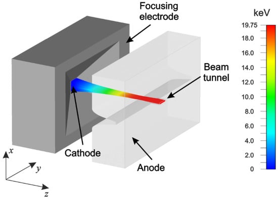
Figure 1.
Schematic of the electron gun design.
The magnetic field distribution was adopted from [19], where the permanent-magnet MFS was designed. The MFS consists of two Nd2Fe14B permanent magnets and iron pole-pieces. The dimensions of the rectangular magnet borehole, where the SWS circuit is to be placed, are 3.8 mm × 65 mm. The MFS provides a 1.1 T axial component of the magnetic field in the beam tunnel. More details on the MFS are provided in [19].
To simulate the electron gun, we use the 3D CST Particle Studio simulator [21]. In the simulations, the anode extracting voltage was set to 19.75 kV. At those parameters, the electron beam current was 94.6 mA. At the cathode, the average current density was 15.6 A/cm2, while in the beam tunnel it was as high as 250 A/cm2, i.e., the achieved compression rate was approximately 16.
Figure 2a demonstrates the positions of the particles in the beam cross-section at a 10 mm distance from the cathode, i.e., at the point close to the SWS beginning. This point is used as the initial beam state for the modelling of beam–wave interaction in Section 4. Despite all the particles having the same energy of 19.75 keV, there is a substantial velocity spread. In Figure 2b,c, the corresponding distributions of the normalized axial and transversal velocities over the beam thickness are presented. Close to the beam axis, at , most of the particles have small transversal velocities. However, increases with the distance from the axis and may be as high as (cf. [19]). The effect of the velocity spread on the beam–wave interaction will be discussed in Section 4.
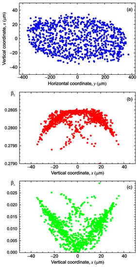
Figure 2.
(a) Electron beam cross-section at 10 mm distance from the cathode, with corresponding distributions of (b) axial and (c) transversal velocities over the beam thickness.
3. SWS Design and Modeling
In Figure 3, a schematic of the DSG SWS unit cell is presented. The dimension parameters of the G-band are given in Table 1. The dimensions are the same as those used in our previous work [3,8,9,10], except the beam tunnel height, which was reduced to μm due to a reduction of the beam thickness. The reduction of the beam tunnel height causes a significant increase in the interaction impedance.
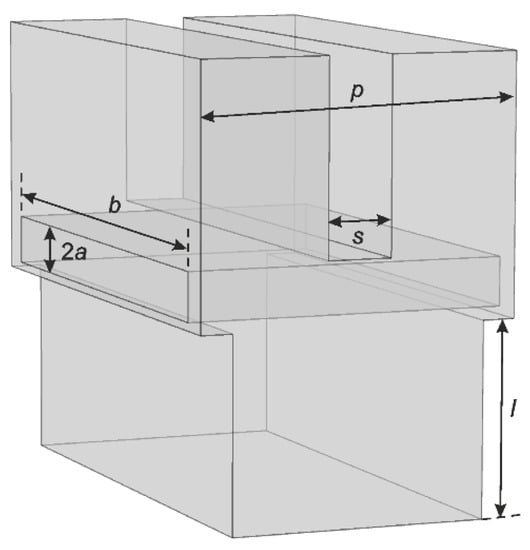
Figure 3.
Schematic of the DSG SWS unit cell.

Table 1.
Dimensions of the DSG SWS.
To calculate the electromagnetic parameters of the DSG SWS, we use the fast and accurate numerical code based on the integral equation method [4] and verify the results using the COMSOL Multiphysics simulator [22]. A dispersion diagram is presented in Figure 4a. The DSG SWS supports propagation of two modes (symmetric and antisymmetric) which coalesce at π-mode frequency that provides a very wide passband of approximately 100 GHz (cf. [3,4,5,6,7,8,9,10,11]). In the dispersion diagram, one can see forward () and backward () spatial harmonics, with propagation constants defined as , . In Figure 4a, a 19.75 kV beam line is also plotted. The beam voltage has been adjusted to provide electron beam synchronism with the 1st forward harmonic at most of the passband. In addition, the beam is in synchronism with the –2nd backward harmonic at approximately 240 GHz. However, the interaction impedance of the backward harmonic is approximately two orders of magnitude less than of the 1st forward harmonic [4,8,10], so there is no danger of backward-wave parasitic self-excitation.

Figure 4.
Electromagnetic parameters of the SWS. (a) Dispersion diagram (blue lines) and 19.75-kV beam line (red line); (b) interaction impedance. On-axis impedance (blue line) and the impedance averaged over the 75 um × 750 um sheet-beam cross-section (red line) are plotted.
Figure 4b shows the on-axis interaction impedance of the operating mode, which attains reasonably high values. In addition, the interaction impedance averaged over the 75 μm × 750 μm sheet-beam cross-section is plotted. The average interaction impedance is much lower than the on-axis impedance. Nevertheless, it is much higher than in [4,8,10] where the beam tunnel height was 150–200 μm.
To compute the transmission characteristics of the complete SWS, we use the CST Studio simulator [21]. In the simulations, the effective conductivity of copper was set to 2.0 × 10⁷ S/m. The value of conductivity has been calculated using the Hammerstad–Bekkadal formula [23] usually applied to evaluate conductivity at THz frequencies, assuming the surface roughness of ~200 nm (see [8] for details).
The structure consists of 50 periods of the DSG SWS with two tapered sections at both ends, which serve to reduce the end reflections. Two designs of the tapers were considered. The initial design often used in DSG SWSs [3,8,12] implies a linear decrease in height of the five end vanes, as shown in Figure 5a. The corresponding S-parameters (curve 1 in Figure 6) exhibit good transmission properties with return loss less than dB at most of the passband (Figure 6b). The transmission loss is better than dB in the GHz frequency range (Figure 6b), which is less than −0.1 dB per SWS period.

Figure 5.
Schematics of the initial (a) and improved (b) input/output taper designs.

Figure 6.
(a)Transmission loss and (b) reflection loss of the complete structure consisting of 50 DSG SWS periods for the initial (red lines) and improved (blue lines) designs of the input/output tapers shown in Figure 4.
However, a reduction of the beam tunnel height to 100 μm increases the reflection at frequencies above 250 GHz. Ripples of the transmission characteristic appear. Thus, we modified the design of the tapers, as shown in Figure 5b. The last five vanes on both sides are now cut at the 6° angle symmetrically with respect to the midplane. This design greatly improves the transmission properties of the SWS (curve 2 in Figure 6). The ripples on the curve completely disappear and the reflection loss becomes less than dB.
4. Beam–Wave Interaction
CST Particle Studio [21] has been used for 3D PIC simulation of the hot-test TWT operation. In the simulation, we consider the 94.6 mA, 19.75 kV sheet electron beam focused by 1.1 T uniform axial magnetic field, with the initial positions and velocities of the particles imported from the results of the electron gun simulation presented in Section 2 (Figure 2). The beam drives the 50-period DSG SWS with input/output tapers optimized as described in Section 3. For that optimized design, we observed stable single-frequency operation without any spurious self-oscillation. Figure 7 shows the waveforms of the input and output signal. The input signal of 1 W power feeds the SWS at 220 GHz. At 0.6 ns, the output signal amplitude becomes constant and does not change with time. The spectrum of the output signal becomes purely single-frequency without any spurious sideband components.
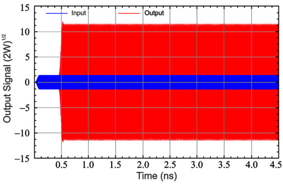
Figure 7.
Input and output signal waveforms at 220 GHz frequency and 1 W input power.
In Figure 8, the plot of saturated output power and corresponding input power versus frequency is presented. The maximal output power of 86 W is attained at 195 GHz. The input power required for saturation is approximately 0.5–1.0 W. The output power exceeds 50 W in a frequency range wider than 50 GHz. Thus, the TWT with the DSG SWS is potentially a very broadband amplifier. However, the broadband operation would require a vacuum window with the same order of bandwidth. The development of windows for 0.22 THz TWT with 20–25 GHz bandwidth has been reported [23,24]. Moreover, recently proposed metamaterial-based windows could greatly expand the bandwidth [25,26,27].
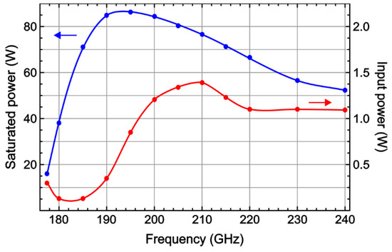
Figure 8.
Saturated output power and corresponding input power versus frequency.
Figure 9 shows the output power and gain versus the input power computed at 0.22 THz frequency. The small-signal gain and saturated power are 23 dB and 66 W, respectively. Note that the increase of the interaction impedance allows a significant decrease of the tube length in comparison with our previous research [8,9,10] (25 mm instead of 40 mm) that will provide a reduction of size and weight of the MFS.

Figure 9.
(a) Output power and (b) gain versus input power at 0.22 THz calculated for interaction with the compressed (squares) and non-compressed (circles) beams with 19.625 kV (red), 19.7 kV (green), and 19.75 kV (blue) beam voltage.
In addition, we calculated the gain and power for the idealized beam emitted from a rectangular cathode immersed in the magnetic field with uniform current density and without any initial velocity spread. Hereinafter, we refer to it as the non-compressed beam. In that case, the number of particles can be significantly reduced. For accurate simulation of the compressed beam (i.e., the beam produced by the EOS with high compression, Section 2), we used approximately 103 injected particles per time step, while the non-compressed beam was reduced to ~250. For selecting the number of macro-particles, we apply two criteria: both the total beam current emitted from the gun and the picture of beam–wave interaction should stay virtually the same as in the case of a higher number of macro-particles. This greatly facilitates PIC modeling and provides a decrease in the calculation time by an approximate factor of 2.5. However, it is necessary to correctly define the effective beam dimensions. As shown in [20], the best agreement is provided for a 75 μm × 750 μm emitting area. This value is the same as that adopted in our previous studies [8,9,10]. The beam current has been set to 94.6 mA, i.e., the same as for the compressed sheet beam, while the beam voltage has been varied.
Figure 9 shows that at 0.22 THz, the small-signal gain decreases with the beam voltage, while maximal saturated power is attained at 19.75 kV. At that voltage, good agreement with the compressed beam is observed at an input power of 0.5 W and above. However, the small-signal gain provided by the compressed beam is the same as that of the 19.7 kV rectilinear beam. This can be explained by the velocity spread (see Figure 2b,c), which reduces the average axial velocity of the compressed beam.
In Figure 10, phase diagrams for the compressed and non-compressed beams at the point of saturation (1.0 W input power) are compared. These diagrams demonstrate the electron bunching processes. Both beams enter the interaction region with the same energy of 19.75 keV (Figure 10a). However, the compressed beam has a significant axial velocity spread, as shown in Figure 10b. The particles with lower are mostly located at the edges of the beam (see Figure 2). Figure 10b clearly demonstrates that at mm, these particles enter the accelerating phase of the wave and their axial velocities increase. As a result, the average axial velocity of the compressed beam approaches that of the non-compressed beam. This explains the equality of saturated power for the compressed and non-compressed 19.75 kV beams (Figure 9a).

Figure 10.
Phase diagrams of the compressed (blue) and non-compressed (red) beams at 19.75 kV voltage, 0.22 THz frequency, and 1.0 W input power. (a) Energies and (b) axial velocities versus axial coordinate z.
Another confirmation is provided by Figure 11 where axial velocity distributions are plotted. At the entrance of the interaction region (Figure 11a), the compressed beam has lower axial velocities of the particles with a significant spread. Figure 11b shows the velocity distributions of the output in the small-signal mode (50 mW input power). In both cases, the distribution is almost symmetric with weakly accelerated and decelerated particles, though it is clear that the average velocity of the compressed beam is still smaller than that of the non-compressed beam. However, at 1.0 W input power (Figure 11c), the velocity distributions become more complex. Peaks appear corresponding to strongly decelerated particles and the average velocities become approximately equal.
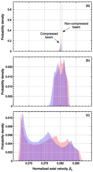
Figure 11.
Velocity distributions for the compressed (blue) and non-compressed (red) beam at the (a) input and output of the SWS in (b) small-signal and (c) large-signal mode.
Despite the high input power level required for saturation, it can be reduced by a moderate increase of the length of the SWS. However, it would require a more complicated design of the interaction structure, which consists of two sections separated by a sever [7], to prevent parasitic oscillations. In this article, we consider a simpler single-section design to be adequate for comparison of the two models of the sheet beam mentioned above.
5. Conclusions
In this paper, we consider the 0.22 THz TWT with DSG SWS driven by a converging sheet electron beam. The electron gun provides a 94.6 mA, 19.75 keV sheet beam with almost 16 times compression in a vertical direction. As a result, the average beam thickness is approximately 75 μm and allows a reduction of the beam tunnel height to 100 μm. This leads to a substantial increase of the Pierce interaction impedance, which in turn makes it possible to reduce the tube size and weight. The improved design of the input/output tapered sections is presented, which significantly reduces the end reflections. Output power and gain of the TWT are investigated by using 3D PIC simulation. The simulation predicts 23 dB small-signal gain and 66 W saturated output power at 0.22 THz.
During the compression, the sheet electron beam acquires a significant velocity spread. As a result, its average axial velocity is reduced. We compare the performance of the TWT driven by the compressed sheet beam and by the idealized beam emitted from a rectangular cathode without any velocity spread. Properly chosen effective beam dimensions provide very good agreement at high input power (0.5 W and above). However, in the small-signal mode, good agreement is obtained when the idealized beam voltage is reduced to 19.7 kV.
Author Contributions
Conceptualization, N.R.; investigation, V.T. and A.P.; methodology, V.T. and N.R.; project administration, N.R.; visualization, A.P.; writing—original draft, V.T. and N.R.; Writing—review and editing, N.R. All authors have read and agreed to the published version of the manuscript.
Funding
This work was supported by the Russian Science Foundation under grant No. 22-49-02017.
Data Availability Statement
The data that support the findings of this study are available from the corresponding author upon reasonable request.
Conflicts of Interest
The authors declare no conflict of interest.
References
- Paoloni, C. Sub-THz wireless transport layer for ubiquitous high data rate. IEEE Commun. Mag. 2021, 59, 102–107. [Google Scholar] [CrossRef]
- Paoloni, C.; Gamzina, D.; Letizia, R.; Zheng, Y.; Luhmann, N.C. Millimeter wave traveling wave tubes for the 21st century. J. Electromag. Waves Appl. 2021, 35, 567–603. [Google Scholar] [CrossRef]
- Shin, Y.-M.; Baig, A.; Barnett, L.R.; Tsai, W.-C.; Luhmann, N.C. System design analysis of a 0.22-THz sheet-beam traveling-wave tube amplifier. IEEE Trans. Electron Devices 2012, 59, 234–240. [Google Scholar] [CrossRef]
- Rozhnev, A.G.; Ryskin, N.M.; Karetnikova, T.A.; Torgashov, G.V.; Sinitsyn, N.I.; Shalayev, P.D.; Burtsev, A.A. Studying characteristics of the slow-wave system of the traveling-wave tube with a sheet electron beam. Radiophys. Quantum Electron. 2014, 56, 542–553. [Google Scholar] [CrossRef]
- Wang, J.; Shu, G.; Liu, G.; Yang, L.Y.; Luo, Y. Ultrawideband coalesced-mode operation for a sheet-beam traveling-wave tube. IEEE Trans. Electron Devices 2016, 63, 504–511. [Google Scholar] [CrossRef]
- Baig, A.; Gamzina, D.; Kimura, T.; Atkinson, J.; Domier, C.; Popovic, B.; Himes, L.; Barchfeld, R.; Field, M.; Luhmann, N.C. Performance of a nano-CNC machined 220-GHz traveling wave tube amplifier. IEEE Trans. Electron Devices 2017, 64, 2390–2397. [Google Scholar] [CrossRef]
- Field, M.; Kimura, T.; Atkinson, J.; Gamzina, D.; Luhmann, N.C.; Stockwell, B.; Grant, T.J.; Griffith, Z.; Borwick, R.; Hillman, C.; et al. Development of a 100-W 200-GHz high bandwidth mm-wave amplifier. IEEE Trans. Electron Devices 2018, 65, 2122–2128. [Google Scholar] [CrossRef]
- Karetnikova, T.A.; Rozhnev, A.G.; Ryskin, N.M.; Fedotov, A.E.; Mishakin, S.V.; Ginzburg, N.S. Gain analysis of a 0.2-THz traveling-wave tube with sheet electron beam and staggered grating slow wave structure. IEEE Trans. Electron Devices 2018, 65, 2129–2134. [Google Scholar] [CrossRef]
- Burtsev, A.A.; Danilushkin, A.V.; Navrotsky, I.A.; Ploskih, A.E.; Ryskin, N.M.; Titov, V.N. Studies on sub-THz sheet-beam TWT with staggered grating slow-wave structure. In Proceedings of the 2019 International Vacuum Electronics Conference (IVEC), Busan, Republic of Korea, 28 April–1 May 2019. [Google Scholar] [CrossRef]
- Ploskih, A.E.; Ryskin, N.M.; Burtsev, A.A.; Danilushkin, A.V.; Navrotsky, I.A. Performance improvement of a sub-THz traveling-wave tube by using an electron optic system with a converging sheet electron beam. Res. Phys. 2019, 12, 799–803. [Google Scholar] [CrossRef]
- Shu, G.; Deng, J.; Xie, L.; Liu, G.; Zhang, L.; Wang, J.; Qian, Z.; He, W. Design, fabrication, and cold test of a high frequency system for an H-band sheet beam travelling wave tube. IEEE Trans. Terahertz Sci. Technol. 2020, 10, 292–301. [Google Scholar] [CrossRef]
- Lu, Z.; Ge, W.; Wen, R.; Wang, Z.; Gong, H.; Wei, Y.; Gong, Y. 0.2-THz traveling wave tube based on the sheet beam and a novel staggered double corrugated waveguide. IEEE Trans. Plasma Sci. 2020, 48, 3229–3237. [Google Scholar] [CrossRef]
- Wan, Y.; Wang, J.; Liu, Q.; Li, X.; Wu, Z.; Liu, G.; Luo, Y. A high-power sheet beam slow-wave structure of traveling wave tubes. IEEE Electron Device Lett. 2001, 42, 747–750. [Google Scholar] [CrossRef]
- Gamzina, D.; Himes, L.G.; Barchfeld, R.; Zheng, Y.; Popovic, B.K.; Paoloni, C.; Choi, E.M.; Luhmann, N.C. Nano-CNC machining of sub-THz vacuum electron devices. IEEE Trans. Electron Devices 2016, 63, 4067–4073. [Google Scholar] [CrossRef]
- Srivastava, A.; So, J.-K.; Wang, Y.; Wang, J.; Raju, R.S.; Han, S.-T.; Park, G.-S. Design of sheet-beam electron gun with planar cathode for terahertz devices. J. Infrared Millim. Teraherz Waves 2009, 30, 670–678. [Google Scholar] [CrossRef]
- Zheng, Y.; Gamzina, D.; Popovic, B.; Luhmann, N.C. Electron beam transport system for 263-GHz sheet beam TWT. IEEE Trans. Electron Devices 2016, 63, 4466–4472. [Google Scholar] [CrossRef]
- Wang, S.; Aditya, S.; Miao, J.; Xia, X. Design of a sheet-beam electron-optical system for a microfabricated W-band traveling-wave tube using a cold cathode. IEEE Trans. Electron Devices 2016, 63, 3725–3732. [Google Scholar] [CrossRef]
- Yang, L.; Wang, J.; Li, H.; Jiang, W.; Dong, K.; Luo, Y. Study of a novel bidirectional compression electron gun for W-band sheet beam TWT. IEEE Trans. Plasma Sci. 2017, 45, 805–810. [Google Scholar] [CrossRef]
- Navrotsky, I.A.; Burtsev, A.A.; Emelyanov, V.V.; Titov, V.N.; Ryskin, N.M. Electron-optic system with a converged sheet electron beam for a 0.2-THz traveling-wave tube. IEEE Trans. Electron Devices 2021, 68, 798–803. [Google Scholar] [CrossRef]
- Ploskikh, A.E.; Titov, V.N.; Ryskin, N.M. Design study of a sub-THz traveling wave tube with a converging sheet electron beam. In Proceedings of the 2021 14th UK-Europe-China Workshop on Millimetre-Waves and Terahertz Technologies (UCMMT), Lancaster, UK, 13–15 September 2021. [Google Scholar] [CrossRef]
- CST Studio Suite Electromagnetic Field Simulation Software; Dassault Systèmes Deutschland GmbH. Available online: https://www.3ds.com/products-services/simulia/products/cst-studio-suite (accessed on 13 November 2022).
- Comsol Multiphysics Engineering Simulation Software; COMSOL Inc.: Burlington, MA, USA, 2020; Available online: https://www.comsol.com/comsol-multiphysics (accessed on 13 November 2022).
- Hammerstad, E.; Jensen, O. Accurate models for microstrip computer-aided design. In Proceedings of the 1980 IEEE MTT-S International Microwave Symposium Digest, Washington, DC, USA, 28–30 May 1980; pp. 407–409. [Google Scholar] [CrossRef]
- Cook, A.M.; Joye, C.D.; Kimura, T.; Wright, E.L.; Calame, J.P. Broadband 220-GHz vacuum window for a traveling-wave tube amplifier. IEEE Trans. Electron Devices 2013, 60, 1257–1259. [Google Scholar] [CrossRef]
- Yang, T.; Guan, X.; Fu, W.; Lu, D.; Zhang, C.; Xie, J.; Yuan, X.; Yan, Y. Over-size pill-box window for sub-terahertz vacuum electronic devices. Electronics 2021, 10, 653. [Google Scholar] [CrossRef]
- Proyavin, M.D.; Sobolev, D.I.; Parshin, V.V.; Belousov, V.I.; Mishakin, S.V.; Glyavin, M.Y. Study of 3D-printed dielectric barrier windows for microwave applications. Electronics 2021, 10, 2225. [Google Scholar] [CrossRef]
- Bai, N.; Shen, J.; Fan, H.; Sun, X.; Pan, P.; Cai, J.; Yu, W.; Feng, J. A broad bandwidth metamaterial pillbox window for W-band traveling-wave tubes. IEEE Electron Device Lett. 2021, 42, 1228–1231. [Google Scholar] [CrossRef]
Publisher’s Note: MDPI stays neutral with regard to jurisdictional claims in published maps and institutional affiliations. |
© 2022 by the authors. Licensee MDPI, Basel, Switzerland. This article is an open access article distributed under the terms and conditions of the Creative Commons Attribution (CC BY) license (https://creativecommons.org/licenses/by/4.0/).