Article

Robotic Manipulation in the Ceramic Industry

1
Engineering Institute of Coimbra (ISEC), Polytechnic of Coimbra (IPC), Rua Pedro Nunes—Quinta da Nora, 3030-199 Coimbra, Portugal
2
GECAD—Knowledge Research Group on Intelligent Engineering and Computing for Advanced Innovation and Development, Engineering Institute of Porto (ISEP), Polytechnic Institute of Porto (IPP), 4200-465 Porto, Portugal
3
INESC TEC—Institute for Systems and Computer Engineering, Technology and Science, 4200-465 Porto, Portugal
*
Author to whom correspondence should be addressed.
Electronics 2022, 11(24), 4180; https://doi.org/10.3390/electronics11244180
Submission received: 15 November 2022 / Revised: 6 December 2022 / Accepted: 8 December 2022 / Published: 14 December 2022
(This article belongs to the Section Power Electronics)

Abstract

:
Robotic manipulation, an area inside the field of industrial automation and robotics, consists of using a robotic arm to guide and grasp a desired object through actuators such as a vacuum or fingers, among others. Some objects, such as fragile ceramic pieces, require special attention to the force and the gripping method exerted on them. For this purpose, two grippers were developed, where one of them is a rotary vacuum gripper and the other is an impact gripper with three fingers, each one equipped with a load sensor capable of evaluating the values of load exerted by the grip actuators onto the object to be manipulated. The vacuum gripper was developed for the purpose of glazing a coffee saucer and the gripper with three fingers was developed for the purpose of polishing a coffee cup. Being that the impact gripper with sensorial feedback reacts to the excess and lack of grip force exerted, both these grippers were developed with success, handling with ease the ceramic pieces proposed.

1. Introduction

In the area of industry there is an increasing adherence to the use of industrial manipulators, which are robots commonly used to grab and handle heavy loads and to execute dangerous tasks, allowing operators to move objects quickly, conveniently, and safely, contributing to reducing both the number of work accidents in the industrial sector as well as the occurrence of musculoskeletal injuries [1]. The industrial manipulator is usually composed of six axes of rotation, each corresponding to a degree of freedom, which determines the movements of the robotic arm in two-dimensional or three-dimensional space [2,3].
Generally speaking, the main problems of human labor in this sector are that it is increasingly sparse, and, due to the fact that ceramic processes can be repetitive and sometimes require the handling of high loads, it can cause long-term physical and psychological problems in the workers [4]. By replacing employees with manipulative robots in this type of work, it is possible to eliminate these problems while reducing the overall process time. This also shows improvements in the replaced employee’s work conditions as their capabilities can be implemented in process supervision or other less dangerous tasks at the factory [5].
This article resumes the development of two grippers, where one of them is a rotary vacuum gripper and the other is an impact gripper equipped with three fingers and load sensors capable of evaluating the values of load exerted by it. The vacuum gripper was developed for the purpose of glazing a coffee saucer and the gripper with three fingers was developed for the purpose of polishing a coffee cup.

2. Materials and Methods

A robotic gripper can be defined as the subsystem of an industrial robot, responsible for maintaining temporary contact with the part to be attached and ensuring a correct handling of the workpiece through pressure generation mechanisms between it and the gripper’s terminations [6,7]. The term gripper can also be applied in cases where the parts are being held through suction (suction cups) or electromagnetism (gripper with electromagnet) [8], or a tool which can be used to perform tasks on a static or slow-moving object, ensuring an accurate process [9].
The main parameters in the selection of a manipulative robot to perform an assigned task can be summarized by the object load, the range of the workspace, and its degrees of freedom. While in the choice of the gripper, there are numerous variants, such as the physical resistance of the object, its shape, the maximum deformation to which it can be subjected, the roughness of the surface [10], and which one out of all four types of grippers have the right properties to manipulate the object. The first type of gripper is the impact gripper, which uses the movement of its fingers to produce the force needed to hold the piece, resembling a human hand grabbing an object. The second one is the ingressive type, which deforms or penetrates the surface of the workpiece to a given depth using needles, pins, or hooks. The contigutive grippers imply direct contact between the gripper and the piece through thermal or chemical support, and at last, the astrictive grippers use vacuum or electromagnetism to grab the object [11,12]. The ingressive and the contigutive grippers cannot be applied to the handle of ceramic pieces because the first deforms the ceramic piece and the second is more suitable for handling micro components. The next sub chapters expose some viable grippers, which are the impact and astrictive type, in the handle of ceramic pieces.

2.1. Mechanical Gripper

It is a final actuator that use fingers triggered by a mechanism to grab an object. The use of replaceable fingers allows their exchange due to wear and interchangeability, that is, the projection of different sets of fingers compatible with the same mechanism to accommodate different models [13]. Although these grippers can easily be adapted to new shapes due to their interchangeability, the added value of the ceramic pieces is low, being not profitable to buy or develop new fingers for the gripper whenever a new ceramic design is brought to the market. Additionally, due to the fact that in the same process, for example, in the transportation of various ceramic products to glaze, there can be various shapes to be manipulated, resulting in a lot of time wasted in the exchange of the gripper’s fingers.

2.2. Gripper with Sensorial Feedback

It is a gripper with sensory feedback capabilities on its fingers to help locate or determine the correct pressure force to apply to the workpiece, allowing the robot to grab more fragile workpieces without the risk of breaking or deforming them with excessive grip pressure. It is also possible to assess whether the gripper is properly holding the piece by comparing the force exerted on each finger. If there is a difference in the force exerted on each finger, it means that the gripper is not grasping the piece correctly, which may indicate that the piece is decentered from the desired position [14,15,16].

2.3. Vacuum Gripper

It uses suction cups to hold parts with flat surfaces through the vacuum created between the suction cup and the surface of the workpiece. One or more suction cups can be used to hold the piece more efficiently. Between all grippers, this is the one that consumes the least energy but is subject to more accidents due to misaligned suction cups and other leaks that do not ensure an airtight seal [17].

2.4. Expansion Gripper

These grippers are used to hold hollow pieces, such as a hollow cup, by expanding a dense rubber material that presses against its inside. This technology allows full liberty to work on the external surface of the workpiece [18], but it can only be used to manipulate hollow pieces.

2.5. Dual Gripper

It is a mechanical gripper with two clamping devices in a final actuator, normally used for pick and place. It reduces the cycle time per part by half by holding two workpieces at the same time. These grippers can also have different shapes to hold two distinct pieces that pass through the same working path or for different jobs in distinct parts of the workpiece [19]. Applying two impact grippers in this mechanism removes the necessity of changing grippers to hold different pieces; however, it does not solve the problem of the necessity to buy new grippers or fingers to manipulate new ceramic designs. An example of this gripper is shown in Figure 1.

2.6. Covered Ceramic Processes

This article covers two different ceramic processes proposed by a client in order to robotize them by replacing human workers with industrial robots. These workers would instead apply their experience in the supervision of these processes or in the inspection of quality and finishing of the ceramic pieces, which is an area that requires new personnel due to the fact that this work is performed by few and aging workers.
One of these covered processes is ceramic glazing, which consists in applying a coating film composed mostly of silica, serving both to give shine to the ceramic piece and to increase its rigidity. Glaze can be applied in two ways: by spraying dry on the surface of the workpiece or by diving the piece into the liquid mixture [20]. This project covers the glaze diving of dishes or trays, currently performed manually by employees that grab incoming ceramic pieces from the bottom base with the fingertips, dipping the ceramic in a large reservoir of glazed liquid to then undergo several circular movements to spread the glaze on the top of the ceramic and to then be placed on a round rotating table to dry.
The other process is ceramic polishing, which is used to remove excess material or to smooth the ceramic [21]. Therefore, the next chapter exposes these processes and the two grippers developed for them, printed on 3D printers of either ABS (styrene butadiene acrylonitrile) [22] or resin. Its models were created virtually using the FreeCAD software.

2.7. Noteworthy Materials

In order to attribute communication between the robot and its gripper, five-pin relays were used, each one with 24VDC on its primary side, provided by one of the digital outputs or the robot, and 5VDC on the secondary side, connected to one of the digital inputs of the Arduino.
The load sensors applied in the three-finger gripper were the fx293x-100a-0025-l, which are amplified load sensors that can measure up to 25 lb (11.34 kg).
One Nema 17 stepper motor was used to give rotary movement to the table and another to the vacuum gripper. To power each finger of the hand-based gripper, a Towerpro MG995 with a torque of 13 kg·cm at 6VDC was used.

3. Results

3.1. Coffee Saucer Glaze

A miniature replica of the existent glazing process was created and adapted to a robot with a suction cup gripper to glaze a coffee saucer. The suction gripper was chosen as this is the gripper most similar to the process of grasping the ceramic to glaze, since in this way, the contact area between the ceramic and the gripper is reduced.
The first step in the development of this process was to create a support that attaches the suction cup to the robot. In order to make the process of spreading the glaze on the top face of the saucer faster and more efficient, rotational movement was given to the suction cup through conical gears moved by a Nema 17 stepper motor.
The robot available already presented a support for a small suction cup, which served as a measuring target for the creation of the final model through reverse engineering. This model was adapted to hold the stepper motor and for the insertion of a bearing on the suction cup shaft, in order to prevent the wear of the material against the rotational movement of the suction cup, as shown in Figure 2.
After finishing the suction cup support model, the file was converted to a format compatible with the 3D printer to print the part in resin, which needs to be placed in an oven with ultraviolet (UV) emissions for 30 min to solidify in its entirety and increase its physical resistance. After this process, the part is ready to be mounted on the robot.
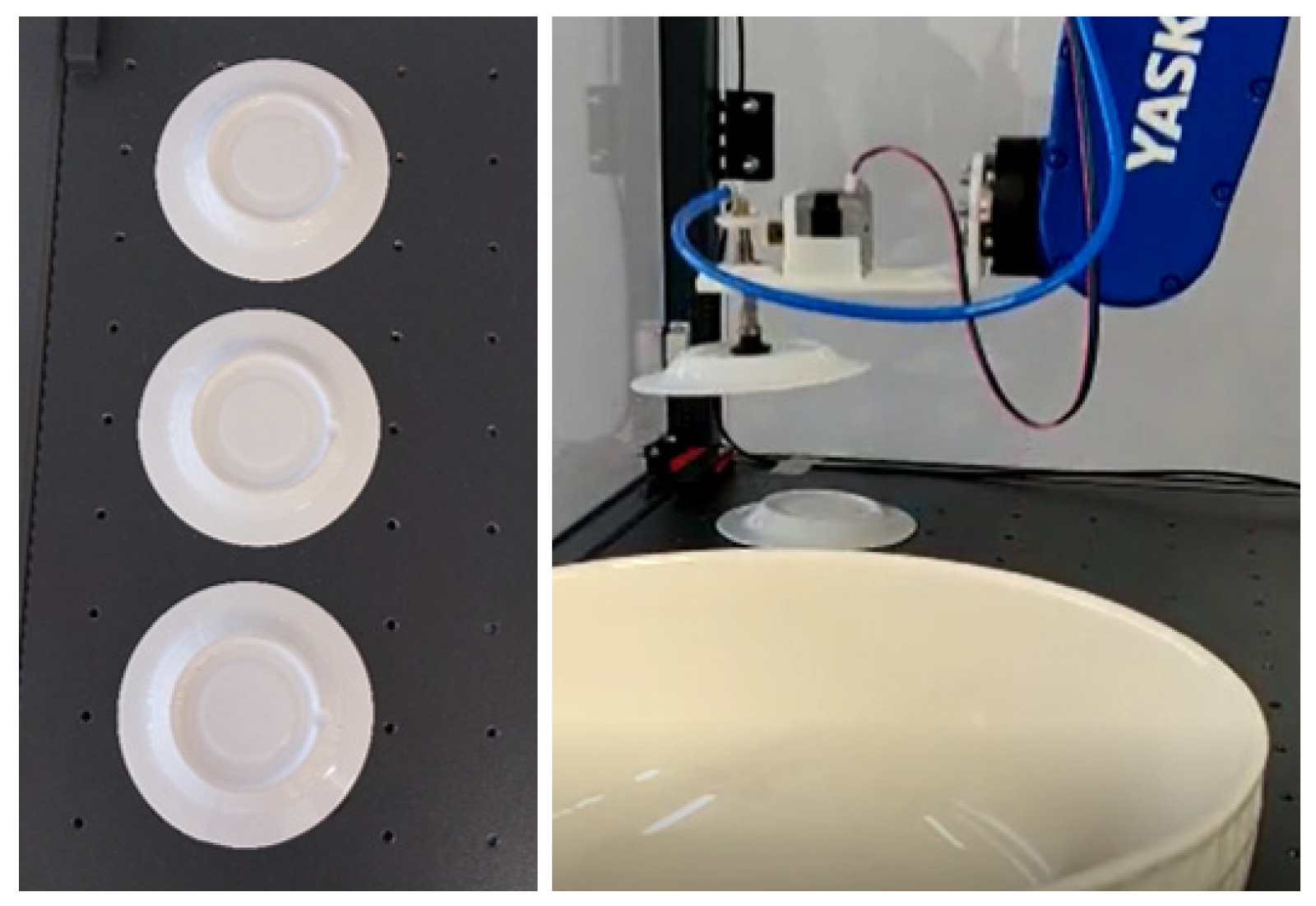
The next step in creating this replica was to develop a round table equipped with rotation through the use of a stepper motor controlled by an Arduino in order to simplify the creation of work cycles for the robot and to automate the process. The idealized table has three slots so the suction cup can place the saucer on the table, holding it by its bottom side. Thus, when the robot places the saucer in an empty slot, it rotates 120 degrees.
The table was also 3D modelled in FreeCAD. In order to calibrate the first position of the slots, a distance sensor was integrated into the table. The material used for printing the table was ABS, which printed parts that were subsequently glued or assembled, as shown in Figure 3.
Once the replica was assembled, the robot’s movement code was created so that it collected the three saucers, one at a time, with the bottom base facing up, as shown in Figure 4.
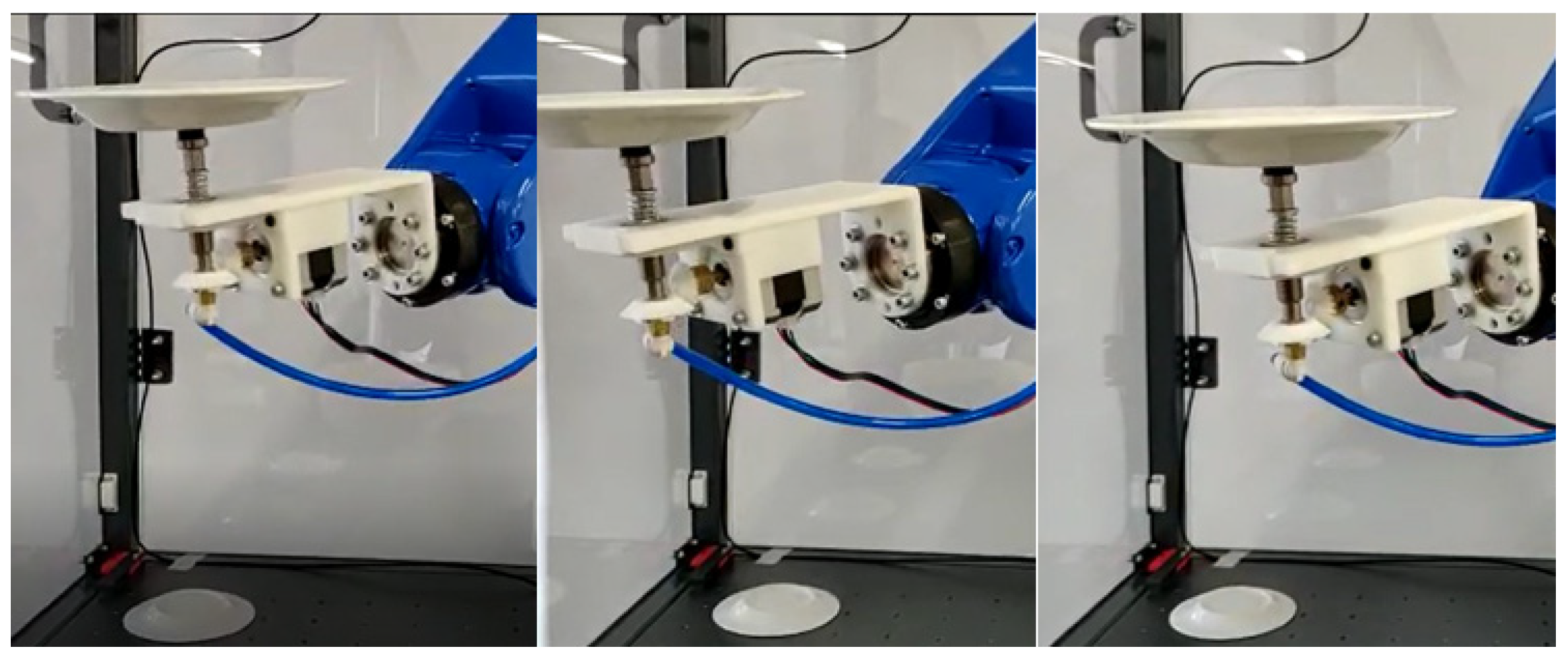
After its collection, the robot turns the top base of the saucer forward, maintaining an inclination so that it enters the tin without collision, rotating the saucer to simulate the dive and application of the glaze according to Figure 5.
The robot then removes the saucer from the tin and, according to Figure 6, turns the top base of the saucer upwards, performing circular movements and applying rotation through the motor to simulate the spread of the glaze.
After performing the circular movement for some time, the robot places the first dish on the table to dry, sending a signal through its digital output to the Arduino to make the table turn 120 degrees clockwise, waiting for the next dish until the three plates are placed on it, as shown in Figure 7. After placing the three dishes on the table, the robot waits a few seconds and fetches the three plates, one at a time, replacing them in their initial place, thus enabling the creation of cycles for this task. This exercise can be seen in Video S2 of the Supplementary Materials.

3.2. Polishing of Coffee Cups

This next miniature replica was created with the end of polishing the bottom base of coffee cups using a manipulation robot, which grabs the cup and touches its lower base to a polisher. To perform the cup grasp, a mechanical gripper with several fingers was developed since the cup exerts continuous collision with the polisher, which requires a greater contact area, grip force, and stability. The gripper fingers are independently actuated and equipped with load sensors in order to apply sensory intelligence to the gripper.
However, the completion of this process underwent several stages of testing and adaptation, starting with the creation of a mechanical tweezer adapted to the shape of the cup, followed by several tests with sensory feedback. The robot used to polish the cup was already equipped with a mechanical gripper actuated by air pressure and with straight tweezers. After some tests with this gripper, it was concluded that this is not ideal for handling the cup since the contact area between the cup and the gripper is very low, sometimes causing the fall and damage of the ceramic material.
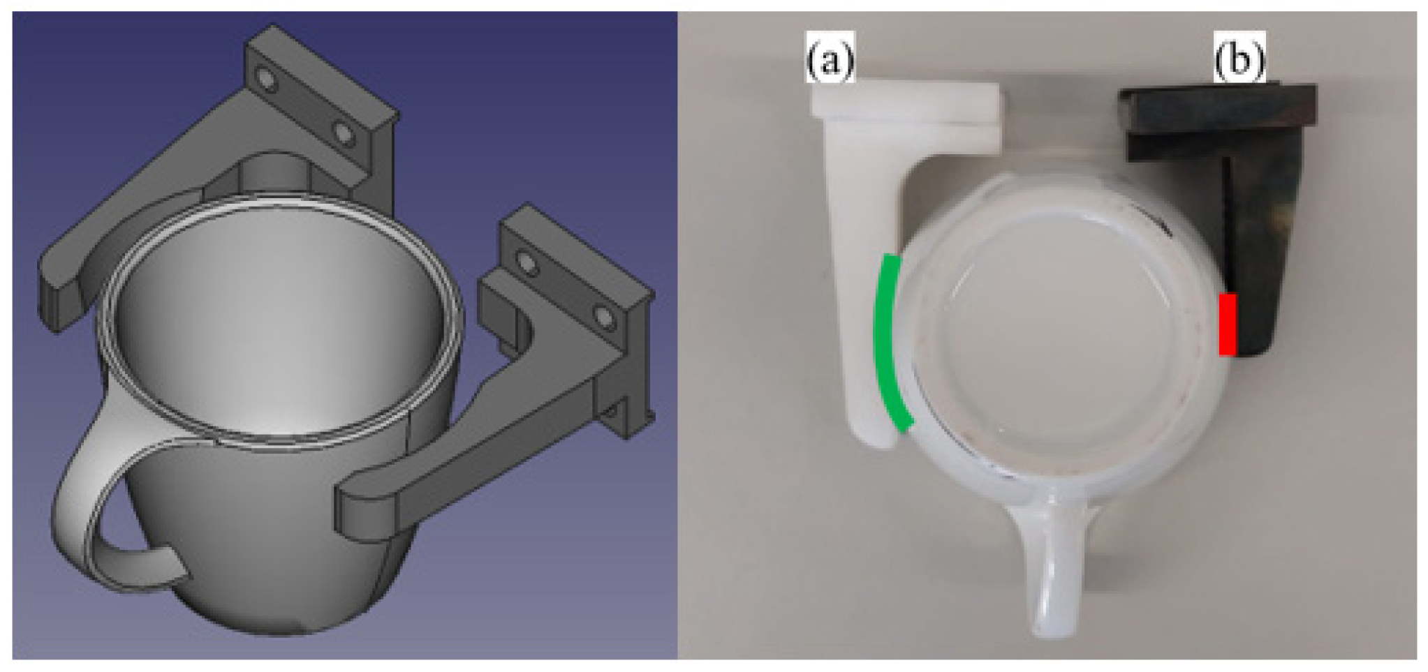
To make the handling process more efficient, it was decided to maintain the drive mechanism, from which it is possible to exchange its tweezers and draw two tweezers with the grasp profile adapted to the cup. The first step was to obtain the 3D model of the test cup, made available by the company’s designer. Then the straight tweezers were scanned to get their 3D model in order to edit so that, instead of presenting straight tweezers, these would form a curve coinciding with the cup’s curve, as shown in Figure 8.
The special profile tweezers (a) drawn with the same profile as the cup to be manipulated have a larger contact area (green) with the cup compared to the contact area of the standard tweezers (red). It is also added that the length of the tweezers (b) is reduced, which in turn reduces the contact area, making it more difficult to manipulate the cup.
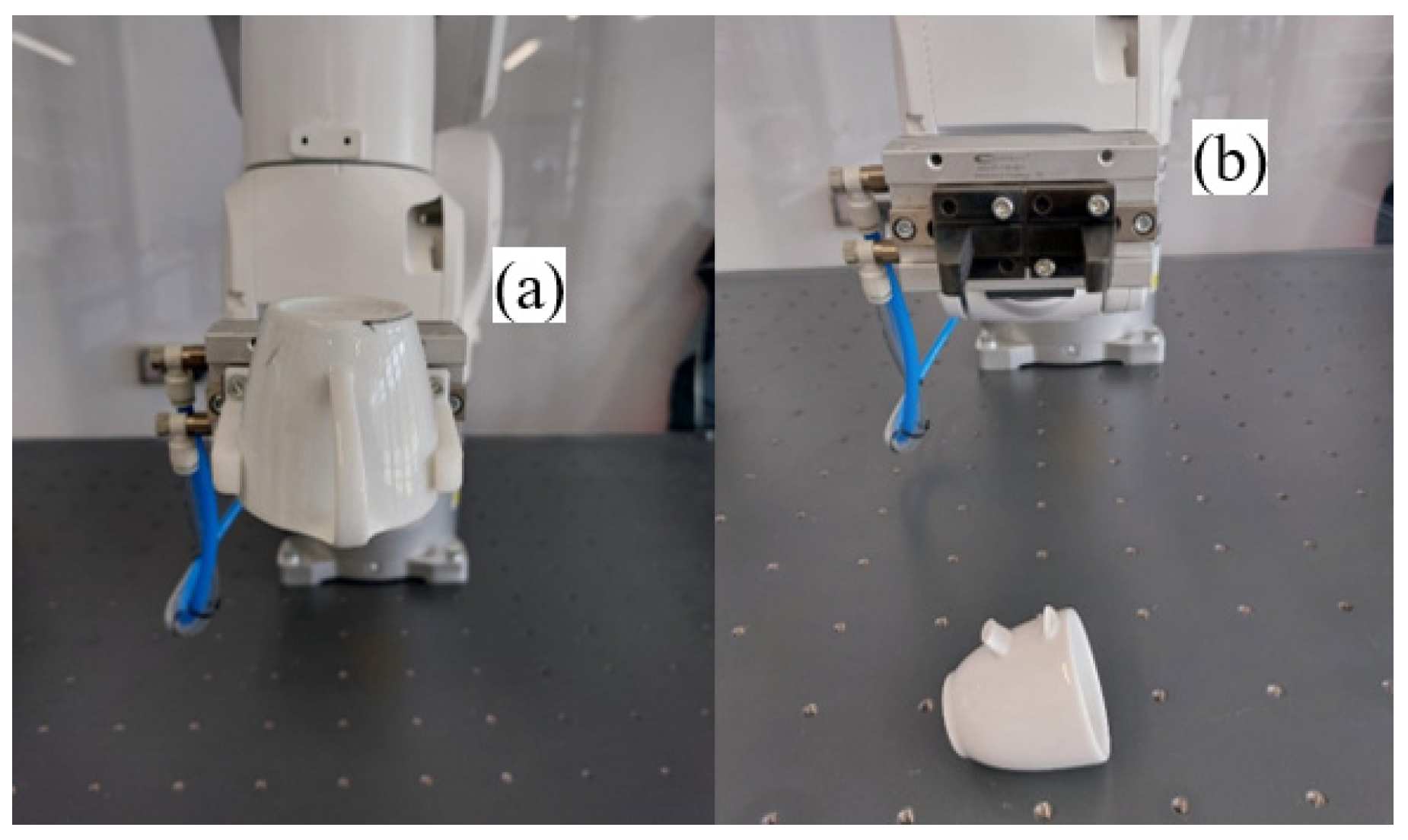
A stability test for both tweezers was realized, where the tweezers had to manipulate the coffee cup, inverting its orientation. Once inverted, the cup has a less favorable position for its grasp due to its conical shape. In the test with the special profile tweezers (a), the gripper did not demonstrate any difficulty in handling the cup; however, in the test with the standard tweezers (b), the cup slipped and was damaged (see Figure 9 and Videos S1 and S3 of the Supplementary Materials).
With the execution of this final test, it was proved that the projection of tweezers adapted to the profile of the ceramic to be manipulated has benefits in its stability compared to the standard tweezers, but it is not profitable to develop special profile tweezers for every different shape of new ceramic pieces.

3.2.1. Gripper with Fingers and Sensorial Feedback

The first step in the creation of the gripper with sensory feedback was the development of a load sensor test circuit, with a load sensor of the FX29 series, powered by an Arduino NANO board, capable of reading the instantaneous values and showing them on a serial port and a LCD display connected to the PCF8574 driver. It was then observed that the values obtained on the LCD screen were comprised in the hundreds, and without any force on the sensor, it presented the value 106. It is also noted that the value shown on the LCD increased according to the force exerted on it.
Because the values obtained are not included in any unit of the International System of Units (SI), a calibration by was performed comparing them in a table with known mass values previously measured on a precision scale and creating the following equation, where “Y” represents the mass converted into grams [g], “X” represents the value obtained by the sensor and “TARA”, which is the value measured without pressure on the sensor, allowing the customization of the zero value by reading the value obtained by the sensor.
Y = 13.7172 ( X T A R A )   [ g ]
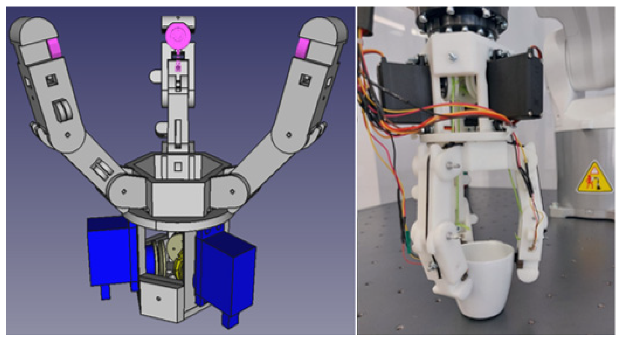
The final gripper to perform the polishing task is a gripper of three articulated fingers, resembling the fingers of a human hand. Each finger is independently actuated by the corresponding servo motor and equipped with a load sensor attached to its end that controls the minimum and maximum load of debit in the coffee cup. The servo motor controls the movement of the finger by pulling a wire and an elastic band, both attached to a screw in one of the elements of the finger; that is, when the servo motor pulls the wire, it is wrapped in a coil closing the gripper, and when the servo motor releases the wire, the elastic pulls the finger so as to open the gripper.
The first step in the development of the gripper was the creation of 3D models of the gripper fingers, each consisting of two pieces that are connected by a shaft, attributing articulated movement through its rotation, and forming a mechanism similar to a “hand”.
To pull the wire that closes the gripper, three positional servo motors (180°) were used. In order to be able to size a support for this servo motor, a 3D model was created in the FreeCAD application with its exact dimensions, along with the rest of the gripper’s body, and also using the robot model, the coils responsible for winding the wires that trade the fingers were developed.
After 3D printing the main elements in resin, their assembly and gluing were realized, obtaining, with the addition of the traction wires, motors and three load sensors, the gripper present in Figure 10.
Once the construction of the gripper was finished, a program in the KUKA robot that simulates the polishing of the cup base was developed, starting by placing the gripper next to the cup so that after triggering the digital output responsible for exciting the circuit, the gripper starts its closure, grabbing the cup.
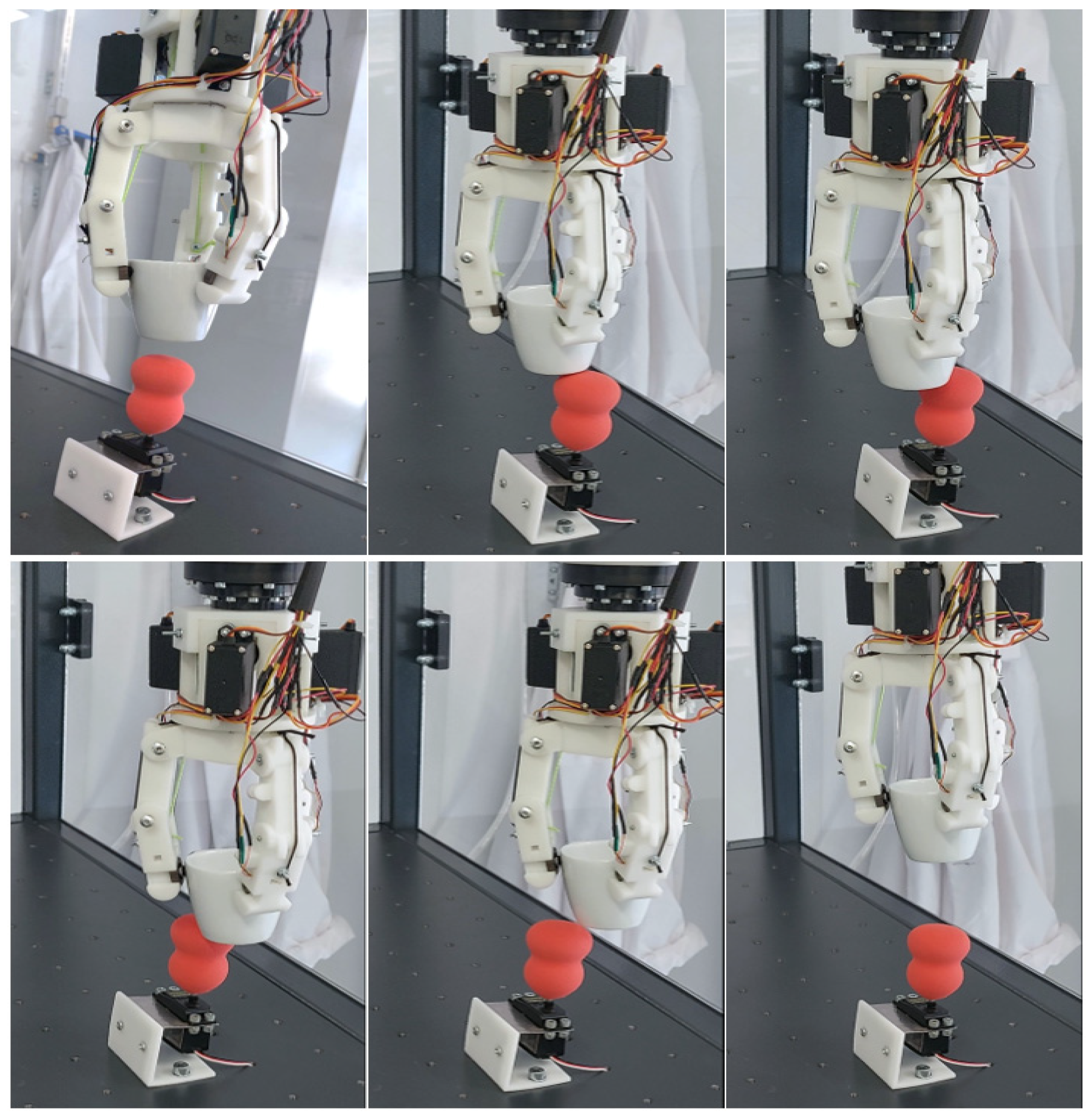
The robot then lifts the cup, placing it in a safe position above the polishing sponge, then lowers it to the point where the base of the cup collides with the sponge, performing two turns according to the Z axis of the gripper so that the base of the cup is polished in its entirety, raising it at the end to a safe position, as seen in Figure 11.
Once the cup base is polished, the robot moves it to its front and rotates it, as shown in Figure 12, thus being possible to observe at the same moment the base of the polished cup and the behavior of the gripper when manipulating the cup in a different orientation. This exercise can be seen in Video S4 of the Supplementary Materials.
After a few seconds in this position, the robot puts the cup back in its original position, then returns to the start position of the program so that it is possible to perform an automatic loop. In the course of this test, the minimum load value for the gripper closure was adjusted to 1.568 N (or 160 g·f) and the values read by the sensors on the gripper fingers were higher than this value, proving the stability in its handling.
The behavior of the gripper was tested in the face of the sudden change of the minimum value of the closing load force, and the maximum, which is two times the minimum value, was applied to the coffee cup. In this sequence, after the cup was grasped with the minimum force of 1.568 N, this value was then reduced to 0.507 N, presenting a reduction in the force exerted by the three fingers of the gripper, which in turn reduced to within the stipulated values. Then, the minimum load value was increased to 1.323 N, which once again caused the gripper fingers to act and exert more force on the cup.
This value was reduced twice more so that only one or two fingers acted; that is, after reducing the minimum load to 0.559 N, it was expected that the values of the loads stabilized to reduce the limit load only enough, corresponding to 0.441 N, so that the finger that is exerting greater force on the cup compensates for its excess strength.
Finally, the value was reduced to 0.363 N in order to test the stability of the gripper in the application of reduced forces, which proved to be quite unstable in previous tests that applied a lower value of maximum load limit, concluding that stability is only observed when the maximum closing load value is at least twice the minimum closing load value., as shown in Table 1.

3.2.2. Tests with Raw Coffee Cup

The following tests was performed with a coffee cup identical to the one used previously but raw and without its handle. The raw ceramic piece, or green, is fragile because it has not yet gone through the cooking process that subsequently attributes rigidity to the piece. Due to this fragility, the minimum load force was reduced to 0.412 N. Once grasped, the raw cup went through the same handling process as the coffee cup previously used without having difficulties in its handling, as shown in Video S5 of the Supplementary Materials.
Then, to test the strength limit of the raw piece, the robot kept the cup suspended a few centimeters from the base of the robot table, and the table was covered by cardboard to protect the controller and its connections. Then, the value of minimum closing force slowly climbed with the end of reaching either the maximum value of the potentiometer or until the cup breaks, recording the values obtained from a linear scale every 40 g of strength (or 0.392 N) added together, obtaining the results presented in Table 2.
When the minimum load value was increased to 4.361 N, the cup broke, as shown in Figure 13, and it was observed that the fingers “C1” and “C3” exerted a load of 4.577 N and the finger “C2” exerted 4.724 N.
With the performance of this test, it was possible to prove that sensory feedback is extremely important in the manipulation of fragile objects, since without this particularity, it would not be possible to manipulate the green cup with the developed gripper.

4. Discussion

Developing the three-finger gripper with sensory feedback allowed us to further study the behavior of impact-type grippers in the area of ceramic manipulation, being a success in the performance of the intended tasks. However, this gripper is only a prototype of testing and exposure, which means it cannot be used in an industrial environment. To make this gripper feasible in an industrial environment, it is necessary to change some of its properties.
Instead of an automaton, an Arduino board was used to feed and program the gripper due to the fact that it is only a prototype for tests that does not require the capacity and speed provided by the automaton. In turn, in an industrial environment, greater responsiveness, speed, safety, and the ability to act for prolonged periods are necessary and are all characteristics of the automaton which the Arduino does not present in sufficiency.
The resin used to print the main body of the gripper is a material with physical properties similar to those of glass, not being very resistant to collisions and falls. These resin properties are not compatible with industry requirements, and it is necessary to use a more robust material for the gripper to “survive” in this environment.
Another important aspect to mention is the exposure of its motion drive components and electrical cables, since in the manufacturing environment, especially in ceramic polishing, there is a lot of dust in the air that damages the motors and the exposed actuation wires. The solution to this problem is to protect the motors and electrical and traction wires by switching altogether the traction wires for metal cables in order to extend the life of the gripper and decrease its maintenance.
The same issues occurred with the vacuum gripper we developed, which was printed in resin and had all mechanisms and wires exposed and is controlled by an Arduino board.

5. Conclusions

In the area of industrial automation and robotics, there is a constant change in the face of its technological world, evolving at an increasing pace. Since the beginning of industrialization, its goal is to increase productivity, where industrial automation and robotics are indispensable for today’s production.
Because of the low added value of the ceramic pieces, it is not feasible for the ceramic companies to buy grippers only suitable for one type of ceramic or to buy interchangeable grippers, so the best option is to buy a gripper that can handle a wider variety of pieces.
The hand-based gripper is a good example of a versatile gripper that can grasp various shapes and forms, and, with further improvements, it can be considered to be an universal gripper, which is a concept of a gripper that can manipulate any object proposed.
To handle dishes or platters, a simple vacuum gripper can be used to grasp such pieces, being able to attribute rotary movement with ease by installing a motor connected to the vacuum cup, as presented in the vacuum gripper developed.
In short, the use of vacuum grippers is a useful option for ceramic manipulation; however, to handle ceramic pieces with more abstract shapes, or porcelain pieces, which are more expensive and fragile, it is preferable to use mechanical grippers with load sensibility in order to handle the pieces with more stability and to control the force exerted into it in order to not break.

Supplementary Materials

The following supporting information can be downloaded at: https://www.mdpi.com/article/10.3390/electronics11244180/s1, Video S1: Cup broke with straight tweezer); Video S2: Glaze with rotary gripper; Video S3: Polishing with adapted tweezers; Video S4: Three finger gripper grabbing cup of coffee; Video S5: Three finger gripper holding raw cup.

Author Contributions

Conceptualization, R.T. and N.F.; methodology, R.T. and N.F.; software, R.T.; validation, R.T. and N.F.; formal analysis, R.T. and N.F.; investigation, R.T.; resources, R.T.; data curation, R.T.; writing—original draft preparation, R.T.; writing—review and editing, R.T. and N.F.; visualization, R.T. and N.F.; supervision, R.T. and N.F.; project administration, R.T.; funding acquisition, R.T. and N.F. All authors have read and agreed to the published version of the manuscript.

Funding

This research received no external funding.

Data Availability Statement

Not applicable.

Conflicts of Interest

The authors declare no conflict of interest.

References

  1. Benotsmane, R.; Dudás, L.; Kovács, G. Survey on New Trends of Robotic Tools in the Automotive Industry. In Proceedings of the Vehicle and Automotive Engineering 3, Miskolc, Hungary, 25–26 November 2022; pp. 443–457. [Google Scholar]
  2. Ribeiro, J.; Lima, R.; Eckhardt, T.; Paiva, S. Robotic Process Automation and Artificial Intelligence in Industry 4.0—A Literature review. Procedia Comput. Sci. 2021, 181, 51–58. [Google Scholar] [CrossRef]
  3. Tuli, T.B.; Manns, M. Hierarchical Motion Control for Real Time Simulation of Industrial Robots. In Proceedings of the 52nd CIRP Conference on Manufacturing Systems, Ljubljana, Slovenia, 12–14 June 2019. [Google Scholar]
  4. Weber, A.; Fussler, C.; O’Hanlon; Gierer, R.; Grandjean, E. Psychophysiological effects of repetitive tasks. Ergonomics 1980, 23, 1033–1046. [Google Scholar] [CrossRef] [PubMed]
  5. Nardo, M.; Forino, D.; Murino, T. The evolution of man–machine interaction: The role of human in Industry 4.0 paradigm. Prod. Manuf. Res. 2020, 8, 20–34. [Google Scholar] [CrossRef] [Green Version]
  6. Tai, K.; El-Sayed, A.-R.; Shahriari, M.; Biglarbegian, M.; Mahmud, S. State of the Art Robotic Grippers and Applications. Robotics 2016, 5, 11. [Google Scholar] [CrossRef] [Green Version]
  7. Shintake, J.; Cacucciolo, V.; Floreano, D.; Shea, H. Soft Robotic Grippers. Adv. Mater. 2018, 30, 1707035. [Google Scholar] [CrossRef] [PubMed] [Green Version]
  8. Zhang, B.; Xie, Y.; Zhou, J.; Wang, K.; Zhang, Z. State-of-the-art robotic grippers, grasping and control strategies, as well as their applications in agricultural robots: A review. Comput. Electron. Agric. 2020, 177, 105694. [Google Scholar] [CrossRef]
  9. Qian, Z.; QingLong, M.; YongQian, X.; Lin, G. The Robot Intelligent Spraying Glazing System for Sanitary Ceramics Industry. In Journal of Physics: Conference Series, Proceedings of the 2020 International Conference on Advanced Materials and Intelligent Manufacturing & Advanced Steel for Automotive Seminar, Guilin, China, 21–23 August 2020; IOP Publishing Ltd.: Bristol, UK, 2020; Volume 1653. [Google Scholar]
  10. Ali, H.; Hoi, L.H.; Seng, T.C. Design and Development of Smart Gripper with Vision Sensor for Industrial Applications. In Proceedings of the 2011 Third International Conference on Computational Intelligence, Modelling & Simulation, Langkawi, Malaysia, 20–22 September 2011. [Google Scholar]
  11. Monkman, G. Robot Grippers. Assem. Autom. 2006, 29. [Google Scholar] [CrossRef]
  12. Samadikhoshkho, Z.; Zareinia, K.; Janabi-Sharifi, F. A Brief Review on Robotic Grippers Classifications. In Proceedings of the IEEE Canadian Conference of Electrical and Computer Engineering (CCECE), Edmonton, AB, Canada, 5–8 May 2019. [Google Scholar]
  13. Hu, Z.; Wan, W.; Harada, K. Designing a Mechanical Tool for Robots With Two-Finger Parallel Grippers. arXiv 2019, arXiv:1902.09150. [Google Scholar] [CrossRef] [Green Version]
  14. Hogrevea, S.; Priggea, M.; Köbischa, K.O.; Tracht, K. Encapsulation of sensory gripper fingers with silicone rubber. Procedia CIRP 2020, 91, 439–444. [Google Scholar] [CrossRef]
  15. Poveda, A.R. Myoelectric Prostheses with Sensorial Feedback. In MEC’02 the Next Generation, Proceedings of the 2002 MyoElectric Controls/Powered Prosthetics Symposium, Fredericton, NB, Canada, 21–23 August 2002; University of New Brunswick: Fredericton, NB, Canada, 2002. [Google Scholar]
  16. Belzunce, A.; Li, M.; Handroos, H. Control system design of a teleoperated omnidirectional mobile robot using ROS. In Proceedings of the 2016 IEEE 11th Conference on Industrial Electronics and Applications (ICIEA), Hefei, China, 5–7 June 2016; pp. 1283–1287. [Google Scholar]
  17. Gabriel, F.; Fahning, M.; Meiners, J.; Dietrich, F.; Dröder, K. Modeling of vacuum grippers for the design of energy efficient vacuum-based handling processes. Prod. Eng. Res. Devel. 2020, 14, 545–554. [Google Scholar] [CrossRef]
  18. Kumar, R.; Yadav, H.; Gupta, V.; Khatait, J.P. Flexure based gripper to grasp hollow objects by internal surface interaction. Proc. Inst. Mech. Eng. Part C J. Mech. Eng. Sci. 2022, 236, 4085–4092. [Google Scholar] [CrossRef]
  19. Sriskandarajah, C.; Shetty, B. A review of recent theoretical development in scheduling dual-gripper robotic cells. Int. J. Prod. Res. 2018, 56, 817–847. [Google Scholar] [CrossRef]
  20. Aksoy, G.; Polat, H.; Polat, M.; Coskun, G. Effect of various treatment and glazing (coating) techniques on the roughness and wettability of ceramic dental restorative surfaces. Colloids Surf. B Biointerfaces 2006, 53, 254–259. [Google Scholar] [CrossRef] [PubMed] [Green Version]
  21. Li, L.G.; Zhuo, Z.Y.; Kwan, A.K.H.; Zhang, T.S.; Lu, D.G. Cementing efficiency factors of ceramic polishing residue in compressive strength and chloride resistance of mortar. Powder Technol. 2020, 367, 163–171. [Google Scholar] [CrossRef]
  22. Selvamani, S.K.; Samykano, M.; Subramaniam, S.R.; Ngui, W.K.; Kadirgama, K.; Kanagaraj, G.; Idris, M.S. 3D printing: Overview of ABS evolvement. AIP Conf. Proc. 2019, 2059, 020041. [Google Scholar]
Figure 1. Dual gripper.
Electronics 11 04180 g001
Figure 2. Model and prototype of the rotary suction cup. Source: (Own).
Electronics 11 04180 g002
Figure 3. Rotary table and its model. Source: (Own).
Electronics 11 04180 g003
Figure 4. Arrangement and grasp of the saucers. Source: (own).
Electronics 11 04180 g004
Figure 5. Simulation of the saucer’s diving. Source: (Own).
Electronics 11 04180 g005
Figure 6. Simulation of glaze dwell with rotation. Source: (own).
Electronics 11 04180 g006
Figure 7. Drying table rotations. Source: (Own).
Electronics 11 04180 g007
Figure 8. Model and prototype of tweezers adapted to the cup. Source: (own).
Electronics 11 04180 g008
Figure 9. Test with special profile tweezers (a) and standard tweezers (b). Source: [7].
Electronics 11 04180 g009
Figure 10. Three-toed model and gripper. Source: (own).
Electronics 11 04180 g010
Figure 11. Polishing of the cup handled by the three-toed gripper. Source: (own).
Electronics 11 04180 g011
Figure 12. Display of the base of the cup. Source: (own).
Electronics 11 04180 g012
Figure 13. Gripper handling and breaking the raw cup. Source: (Own).
Electronics 11 04180 g013
Table 1. Force exerted by the gripper by variation in the potentiometer. Source: (Own).
Load on Fingers (N)Limits Applied (N)
C1C2C3Minimum LimitMaximum Limit
1.7441.7441.8821.5683.136
0.9410.8040.9410.5101.020
1.8821.3451.8821.3232.646
0.8040.6660.9410.5591.118
0.8040.8040.6660.4410.882
0.5290.5290.5290.3630.726
Table 2. Load values of the stiffness test. Source: (own).
Load on Fingers (N)Limit and State of Cup
C1C2C3Minimum Limit (N)Cup
0.5190.4610.4610.412OK
0.8920.8430.8720.833OK
1.2941.2841.2541.225-
1.7841.7841.6861.617-
2.0192.0972.2442.009-
2.5682.5682.5682.401-
3.0973.1163.0872.793-
3.5483.6363.5182.185-
3.8913.6463.8913.577-
4.1654.2434.1553.969-
4.5774.7244.5774.361BROKE
Publisher’s Note: MDPI stays neutral with regard to jurisdictional claims in published maps and institutional affiliations.