Abstract
Neuromorphic systems are bio-inspired and have the potential to break through the bottleneck of existing intelligent systems. This paper proposes a neuromorphic high-speed object recognition method based on DVS and SpiNNaker and implements a system in which an OR logic aggregation algorithm is used to acquire sufficient effective information and the asynchronous sparse computing mechanism of SNNs is exploited to reduce the computation. The experiment’s results show that the object detection rate of the designed system is more than 99% at the rotating speed of 900~2300 rpm; its response time is within ; and it requires 96.3% less computation than traditional recognition systems using the same scaled ANN.
1. Introduction
High-speed object recognition has been widely used in various fields, including autonomous driving, aerospace, sports photography and science experiments recording. While deep neural networks based on frames have shown impressive performance in high-speed object recognition [1,2,3], there are some limitations:
- The frame-based camera suffers from motion blur, which decreases the accuracy of recognition;
- There is high power consumption due to high data throughput and a huge number of multiply-add operations;
- The computation of such a full matrix deep neural network takes a large amount of time, which causes an unacceptable latency for high-speed recognition tasks.
An ideal high-speed object recognition system should have the characteristics of high accuracy, low power consumption and low latency. Since information is delivered as spikes, the third generation of neural networks, known as spiking neural networks (SNNs), have the sparsity of asynchronous computing. In comparison to artificial neural networks (ANNs), SNN’s utilization of bionic neurons allows the processing of information in the manner of the human brain, and it has the advantages of low power consumption and low latency, as well as a natural spatiotemporal information processing performance. However, SNNs can only benefit from their low power consumption and low latency if they are deployed on a neuromorphic computing platform [4,5,6]. At present, many neuromorphic computing platforms such as SpiNNaker [7,8], Loihi [4] and TrueNorth [9] have been developed. For data acquisition, high temporal resolution and low latency are required in high-speed scenarios. Dynamic vision sensor (DVS) [10], a neuromorphic vision sensor, has these characteristics, and the output is an asynchronous event stream rather than frames, which matches the asynchrony of SNN.
In this paper, we propose a novel high-speed object recognition method based on DVS and SNN and implement the corresponding recognition system using a neuromorphic computing platform. Experiments show that the system performs well at various speeds and is easy to transfer across different platforms. The main contributions of this paper can be summarized as follows:
- We present a high-speed object recognition system built on DVS and SpiNNaker that has a high level of adaptability to varied object speeds, high detection rate (more than 99%) and low latency (within ).
- On the DVS-based dataset, there is no degradation in accuracy for the SNN on SpiNNaker through comparative experiments, and the SNN running on SpiNNaker reduces the number of FLOPs by 96.3% compared to ANNs of the same scale.
- It is easy for the system to transfer to neuromorphic simulators without retraining.
The remainder of the paper is organized as follows: Section 2 introduces related work about DVS and SNN; Section 3 presents the neuromorphic high-speed object recognition method; Section 4 analyzes experiment results and evaluates the performance of the system; Section 5 goes to conclusions of the paper.
2. Related Work
DVS is a novel neuromorphic vision sensor and records light intensity changes, whose output is events. Compared with traditional frame-based cameras, DVS has advantages of high temporal resolution (), high dynamic range (over ), ultra-low power (), and high pixel bandwidth (), which makes it more attractive than frame-based cameras for processing vision tasks such as image reconstruction [11,12,13], video frame interpolation [14,15], and object detection [16,17,18] in low light, high speed, and other extreme environments. Tulyakov, S. et al. [14] demonstrated the advantages of high temporal resolution and low latency of DVS to obtain better results in video frame interpolation applications. Perot, E. et al. [16] proposed a high-resolution large-scale dataset for object detection and demonstrated that DVS can perform comparable object detection tasks without image reconstruction.
Considering the compatibility between DVS and SNN which are bio-inspired, the study of combining them is an active research [19,20,21,22,23,24]. Liu, Q. et al. [21] extracted motion features from the event stream and built a hierarchical SNN for action recognition. Zhang, J. et al. [22] proposed an event-based object tracking method, in which SNN was introduced for tracking temporal cues. Viale, A. et al. [23] applied SNN, combined with DVS, in autonomous driving to recognize cars, and mapped the SNN on Loihi, which achieved both low latency and low power consumption.
When it comes to the experimental scene, some research employed rotating fans to simulate high-speed scenes and performed several computer vision tasks [25,26,27,28]. Zhao, J. et al. [25] and Zheng, Y. et al. [26] applied a neuromorphic vision sensor in image reconstruction of high-speed motion scenes. Zhang, S. et al. [28] presented an adaptive framework for detecting high-speed moving objects by combining DVS with traditional detection algorithms and showed that DVS could get sharp contours without motion blur, which was helpful for feature extraction and recognition. In this paper, we employ DVS to acquire data from a similar experimental scene and apply an SNN for recognition. By combining asynchrony and sparsity, we significantly reduce the latency and computation.
3. Methodology
3.1. Events Aggregation Algorithm
The output of DVS is an event stream, and each event can be represented by a 4-dimensional vector , where denote the pixel coordinate; denotes the time stamp; the polarity parameter, , can has a value of 0 or 1, with 1 signifying an increase in light intensity and 0 denoting a reduction. Figure 1 depicts the event stream.
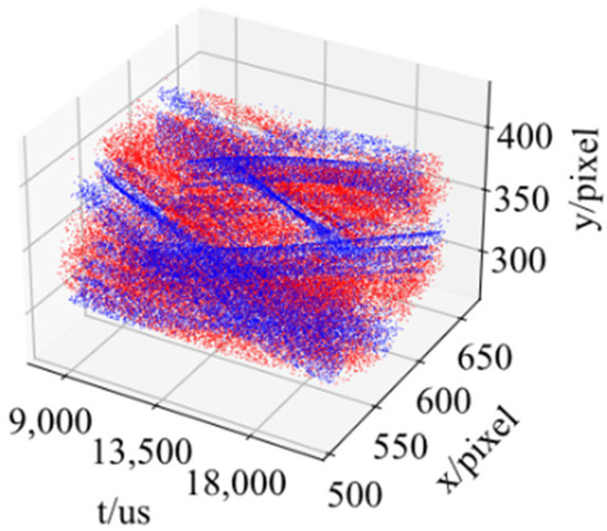
Figure 1.
Illustration of event stream, where blue points represent positive-polarity events, and red points represent negative-polarity events.
In order to acquire enough information for the recognition, the events within a particular time interval are aggregated along time dimension to produce an event slice. This aggregation process can be expressed in Equation (1).
where is the set of events within the time interval; is the event with time stamp of ; is the length of time interval; is the event slice; represents aggregation functions [29], which includes accumulation aggregation [30], non-polarity aggregation [31], OR logic aggregation [32], etc. All of these aggregation algorithms were compared in the experiment, and OR logic aggregation achieved the best performance due to its more stable features and less noise, which is shown in Figure 2. The whole process of OR logic aggregation can be expressed in Equation (2).
where is defined as: . In summary, if a pixel produces at least one positive event in a certain time interval, the aggregation result on its position is set to 1, otherwise the value is 0. Since OR logic aggregation results in a binary image, it can be directly used as the input of SNN. In the experiment, we created a DVS-based dataset using the event slices aggregated by OR logic aggregation algorithm and evaluated its quality, which will be demonstrated in Section 4.2.
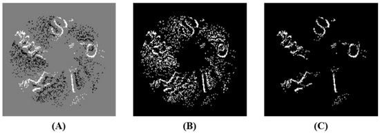
Figure 2.
Visualization of event slices aggregated by different algorithms. (A) is accumulation aggregation; (B) is non-polarity aggregation; (C) is OR logic aggregation. Accumulation aggregation generates intensity images while OR logical aggregation results in binary images with much less noise than non-polarity aggregation.
3.2. Spiking Neural Network Models
Various neuron models can be applied to construct SNNs. Hodgkin-Huxley model [33] is a biologically interpretable model, which uses variable conductance to simulate the opening and closing of ion channels on the membrane of biological neurons. However, since its dynamic equation involves multiple coupled differential equations, the computation is complex and not suitable for large-scale networks. Izhikevich’s model [34] greatly simplifies Hodgkin-Huxley’s model and reduces the number of parameters, where the total of twenty spike firing modes can be simulated with only four parameters. However, driven by nonlinear differential equations, the Izhikevich model is still computationally intensive. Therefore, the LIF [35] neuron model is used in this paper, which can be described by only one first-order linear differential equation shown in Equation (3).
where is the membrane voltage; is the external input like the increment of voltage, which is provided by neurons in the previous layer or external stimulations; is called time constant, which is equal to the product of membrane resistance and capacitance, describing the decay rate of membrane voltage; is the reset voltage.
The LIF neuron model needs to be manually reset after firing, and in practice, discretization for the dynamics is required. The charging, discharging, and resetting process in the discretized model can be expressed by Equation (4).
where is the time step index; is the hidden state of neurons, which represents the instantaneous state of neurons before firing spikes; is the state update function of neurons; represents the spike train; is the step function; is the threshold voltage. The state update function of the LIF neuron used in this paper can be derived by Euler method to obtain its discrete form as shown in Equation (5).
For the network structure, this paper builds a fully connected SNN with two layers using the LIF neurons defined above. Since the event slices generated by OR logic aggregation has clear features, experiments show that a two-layer SNN without hidden layers is adequate to the recognition task. Furthermore, the network completes the computation in just one time step, which lowers latency. The firing and propagation of spikes in SNN is illustrated in Figure 3. When a sample is fed into the network, some specific input neurons will send spikes to all output neurons, then the output neuron that represents a particular class will fire a spike, thus completing the recognition.
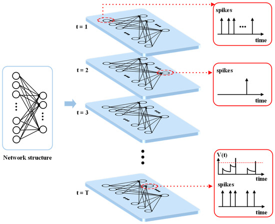
Figure 3.
Illustration of the firing and propagation of spikes in the SNN. Each neuron in the network receives both spatial spikes from various neurons and temporal spikes at different times. These spikes will cause the change of membrane voltage of neurons, and if it exceeds , its value will be reset to after the neuron fires a spike to the connected neurons.
In terms of network learning algorithm, the gradient-based backpropagation methods cannot be utilized in SNN effectively because of its non-differentiability. At present, ANN-to-SNN conversion methods [36,37,38,39] and surrogate gradient (SG) methods [40,41,42,43,44] can overcome the problem and achieve the prominent performance. Since the SG methods train SNNs with low latency, they are more suitable for high-speed object recognition scenarios. This paper applies continuous sigmoid function [45], and makes use of its gradient to surrogate the gradient of step function in backpropagation. In addition, during the process of backpropagation, partial derivatives in time and space are computed separately.
3.3. Deployment on SpiNNaker
SpiNNaker is a successful general-purpose neuromorphic computing platform based on traditional hardware, which enables real-time, low-power and large-scale neural network simulations, as well as supporting more types of neuron models than dedicated neuromorphic computing platforms. Therefore, this paper employs it to deploy the above SNN.
Because neuron models provided in SpiNNaker are connected by synapses, which will convert spikes into electrical currents when transferring them, the computation of SNNs on SpiNNaker is different from that on CPU/GPU in Section 3.2. Furthermore, the currents will be affected by related parameters of neurons, hence the charging and discharging process in Equation (4) should be adjusted, resulting in Equation (6).
where denotes the input current; denotes the membrane resistor; denotes weights of synapses in the layer; denotes the simulation time step; denotes the spike train fired by neurons in the layer; is a constant which is related to in Equation (3), and can be expressed in Equation (7).
In summary, for data acquisition, DVS is used to acquire an asynchronous event stream, and the event stream will be aggregated to slices using OR logic aggregation. For recognition, a trained SNN is deployed on SpiNNaker, and the recognition result can be obtained by monitoring the spike fired by output neurons. The flow chart of the whole method is shown in Figure 4. In practice, in order to exclude invalid and redundant inputs, a selection strategy is introduced in data acquisition, which will be explained in Section 4.2.
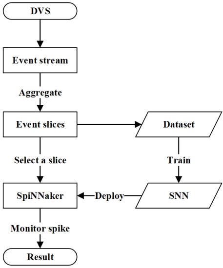
Figure 4.
Flow chart of the proposed neuromorphic high-speed object recognition method based on DVS and SpiNNaker. During the training and deployment process, the output of DVS converts to event slices through OR logic aggregation algorithm, and a specific dataset can be created via these slices. Then an SNN is trained through this DVS-based dataset and deployed on SpiNNaker after that. For the inference process, the stream of events acquired in real-time is aggregated into consecutive event slices and fed into SpiNNaker as spikes. After the computation of the SNN, the neurons in output layer will fire corresponding spikes, which refers to the recognition result.
4. Experiments and Analysis
4.1. Implementation of System
In this section, a neuromorphic high-speed object recognition system using the proposed method was implemented. The whole system is shown in Figure 5. The specific hardware used in the system is Prophesee Gen 4 and a SpiNNaker 101 machine. Through a USB link, the host configures and controls DVS by a data acquisition program. To configure relevant runtime parameters and download the trained SNN model onto the board, the host and SpiNNaker board communicate via Ethernet. The monitor program running on the host supervises the firing activity of output neurons in real time.
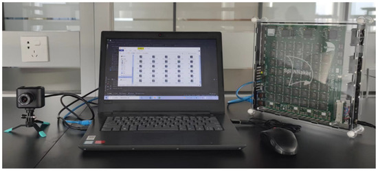
Figure 5.
Photograph of the designed neuromorphic high-speed object recognition system based on DVS and SpiNNaker. In the system, DVS and SpiNNaker are both configured, controlled and monitored by a laptop.
In the experiment, we built a fully connected SNN with 2 layers, including an input layer with 1600 LIF neurons (the size of input event slices is 40 × 40) and an output layer with 5 LIF neurons (5 classes). Each input neuron was one-to-one correspondent to an event position, and each output neuron represented a class. When an event slice was input into the SNN, only the target output neuron would fire a spike. Compared with traditional ANNs, the proposed network was independent of specific classification layers like argmax, softmax, etc., thus able to recognize objects much easier and faster. The experiment showed that some parameters of LIF neurons had impact on the performance of SNNs in both training and inference. The main parameters and models used in the system are shown in Table 1.

Table 1.
Parameter values and model types used in the experiment.
4.2. Data Acquisition and Evaluation
Under laboratory conditions, this paper used a speed-adjustable fan as the high-speed scenario and recognized the letters on the blades, which is shown in Figure 6. There were 5 letters to recognize and the range of the rotating speed of the fan is from to . In order to only acquire one letter at a time, an ROI would be automatically set in advance, and only events in the area were taken into account. The steps to set the ROI are shown in Figure 6.

Figure 6.
Illustration of setting a ROI. First, the events over a long period of time are aggregated, and due to the rotation of the fan, a ring will be formed. The image is then filtered and clustered to remove noise, and two concentric circles are fitted. Finally, a square ROI is anchored just above the center of the circle with the radius difference between the two circles as the side length.
Data acquisition was implemented in two steps: aggregation and selection. For aggregation, the event stream within a certain interval was aggregated to generate an event slice by OR logic aggregation algorithm. The experiment showed that when time interval was set to , event slices were able to contain sufficient information of letters. Some aggregated event slices are visualized in Figure 7, where the pixel with value equal to 1, namely white pixel, is called “event pixel”. When a slice was fed into the SNN, event pixels would activate, instructing their corresponding neurons in the input layer to fire spikes.
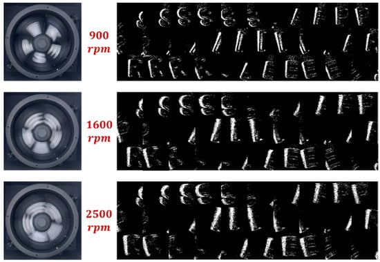
Figure 7.
RGB images captured by a frame-based camera and event slices captured by the DVS at different speeds. Event slices aggregated by OR logic aggregation algorithm contain clear letter edges at all rotating speeds, while for RGB images, the motion blur gets worse as the rotating speed rises.
For selection, since there were lots of useless event slices generated in aggregation step, a selection strategy was introduced to filter out invalid and redundant slices, which is illustrated in Figure 8. Experiments show that the number of event pixels in aggregated event slices is statistically significant under a fixed environment, as shown in Figure 8A. When letters rotate to the center of the ROI, the number of event pixels gradually increases; when letters rotate out of the ROI, the number of event pixels gradually decreases. In this paper, a Gaussian mixture model is used to fit the change in the number of event pixels, and then the event slices containing letters can be detected, as shown in Figure 8B. In order to avoid repetitive recognition of an identical letter in different locations, only slices with the letter in their center were selected to feed into the network after resizing to 40 × 40. In this manner, each letter would only be recognized once for each revolution of the fan.
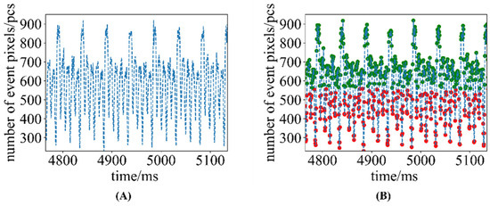
Figure 8.
Illustration of the selection strategy. (A) is the change in the number of event pixels in the ROI over time when the fan rotates. (B) is the result of using the Gaussian Mixture Model to separate out event slices containing letters. We discard invalid event slices that do not contain letters, and select only one event slice per letter for recognition.
Then a DVS-based dataset was created using the selected event slices, which totally contained 49,032 slices for 5 letters at different rotating speeds. In fact, the event slices were the trails of letter edges, and there was some noise if the event stream was aggregated directly.
4.3. Results Analysis
In the experiment, we evaluated the performance of the SNN-based system in terms of detection rate, response time and power consumption. Furthermore, in order to demonstrate the superiority of the neuromorphic system, we conducted some comparison experiments, including different platforms, datasets, and neural networks. In addition, we also verified the portability of the system on a simulator.
4.3.1. Performance Evaluation
The real-time performance of the designed system was evaluated under conditions similar to those of the DVS-based dataset. For the detection rate of the system, it is the product of the selection strategy success rate and the network recognition accuracy. After testing, when the fan speed was below , our selection strategy worked well and the success rate remained above 99%; when the rotating speed exceeded , the success rate of the selection strategy dropped rapidly, and we considered the strategy a failure. For recognition accuracy, since DVS could acquire clear letters at all speeds, the recognition accuracy of the SNN after training remained above 99% in the experiment, which is shown in Table 2. Here we take the rotating speed of for example.
Table 2.
Comparison of the SNN/ANNs on the DVS-based/RGB datasets.
Response time mainly includes aggregation time and computing time. The aggregation time interval is , as mentioned above, and the computing time is equal to or , which is shown in detail in Figure 9.
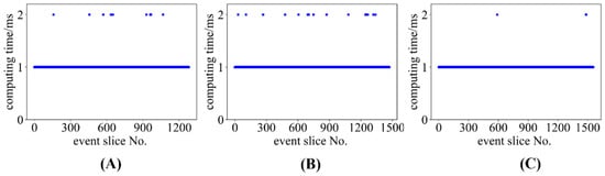
Figure 9.
Computing time of SpiNNaker at different rotating speeds. (A) is computing time at ; (B) is computing time at ; (C) is computing time at . The computing time is basically kept at at all speeds, except for some outliers of .
In the experiment, computing time was measured through the internal clock in SpiNNaker with the highest precision of . Theoretically, because SpiNNaker’s interlayer computation required one delay of and our network only had input and output layers, the computing time should always be . However, as shown in Figure 9, there were some outliers with value of . By analyzing the relationship between computing time and the number of event pixels that shows in Figure 10A–C, as well as conducting repetitive experiments shown in Figure 10D–F, we found that these outliers might occur when event pixels (i.e., input spikes) were more than 150. The reason was that, in SpiNNaker, when a neuron received a large number of spikes in one time step, it would receive these spikes in batches, which prolonged the computing time accordingly. However, not all inputs in the experiment with more than 150 event pixels produced outliers, because the clock’s precision was and if the starting point and the end point fell in adjacent time intervals while measuring the computing time, the final reading would be .
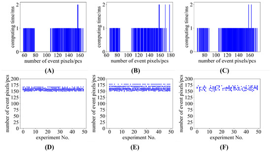
Figure 10.
Computing time along with number of event pixels and the number of event pixels in outliers in repetitive experiments. (A–C) are computing time at , and , respectively; (D–F) are the number of event pixels in outliers at , and , respectively. Outliers with computing time of probably occur when event pixels are more than 150.
Considering these outliers, the maximum response time was , meeting the requirement of the fastest speed of in the experiment, i.e., completing recognition within . And according to the configuration of the experiment, amounted to about .
4.3.2. Comparisons and Analysis
We conducted comparative experiments in three aspects: deployment platforms, datasets and neural networks. For the deployment platform, we deployed the SNN on an i7-9700 CPU for recognition. For the dataset, we created an RGB dataset using an iPhone 13 pro max at 240 FPS in the same experimental scenario, which contained 21,430 samples. For neural networks, we built a fully connected neural network (FCNN) with the same scale as the SNN (1600 × 5) and introduced a VGG16 network as well. The comparison results are listed in Table 2.
For SNN, whether it was deployed on CPU or SpiNNaker, its recognition accuracy could reach almost 100%. However, due to its unique computing mechanism, SNN was incompatible with the ordinary CPU architecture, and the benefits of its asynchronous sparse computing in terms of power consumption could only be realized on a dedicated computing platform. In fact, in SpiNNaker, floating point numbers were emulated by fixed point numbers with the highest precision of , while that in CPU was . Hence there would be loss of numerical value in networks while deploying the trained SNN on SpiNNaker. But in the experiment, this loss did not affect the final recognition accuracy of the system, because our network had only two layers, and the loss would not accumulate in computation.
When the RGB camera was employed as the acquisition device, motion blur destroyed the original image features. For FCNN, its recognition accuracy could only reach about 80%, because its expressive power could not effectively extract and recognize features, even if the original features were very simple. The VGG16 had much stronger expressive power, so it could extract features and successfully recognize even images that heavily suffered from motion blur. However, it would involve a lot of computation, which required more than 473 million FLOPs. When the DVS was used as the acquisition device, event slices had a high image quality without motion blur, hence a 1600 × 5 FCNN was adequate to this recognition task, where 24,000 FLOPs were involved (8000 multiplications and 16,000 additions). For our solution of DVS+SNN (SpiNNaker), since only the input neurons corresponding to event pixels sent spikes, the computation of the network would decrease greatly. In the experiment, the maximum number of event pixels was 178, so there were up to 178 × 5 connections involved in computation with the amount of 890 FLOPs (only additions). Compared with the same scaled FCNN, the computation of the neuromorphic system declined by 96.3%, resulting in high energy efficiency.
4.3.3. Portability Analysis
Brian2 is a simulator for spiking neural networks. To verify the repeatability of our system, we reproduced the trained SNN on Brian2, and tested its recognition accuracy and computing time using the DVS-based dataset. The experiment result is shown in Table 3. It could achieve the same recognition accuracy of the SNN on SpiNNaker, while its computing time is over 100 times longer because Brian2 simulates the computing of SNN based on the ordinary CPU architecture and is not comparable with neuromorphic computing platforms. During the simulation, the membrane voltages of five neurons in the output layer were also recorded, as shown in Figure 11. According to Figure 11, when the samples were fed into the SNN in sequence, the output neurons fired spikes in turn, which was consistent with the experimental expectations. This experiment showed that the system could transfer to an SNN simulator without retraining.
Table 3.
Recognition accuracy and computing time of the SNN on Brian2.
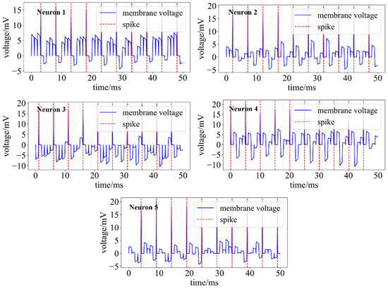
Figure 11.
Membrane voltages of five neurons in the output layer. It takes one time step () to recognize an input, and the neuron representing the recognition result will fire a spike. Additionally, the membrane voltage is reset to ( ) at each time step to eliminate the memory of the previous input.
5. Conclusions
This paper presents a neuromorphic high-speed object recognition method and system, which applies OR logic aggregation algorithm to acquire enough effective information, and utilizes SNNs to reduce computation in recognition, where the SNN uses LIF neurons and is trained through a surrogate gradient method. The asynchrony and sparsity of DVS and SpiNNaker are used in the implementation of the system to achieve both high-speed data acquisition and computation.
In the experiment with rotating speed from to , the system achieves the detection rate of more than 99%, and the response time of each letter is within . In addition, due to the computing mechanism of SNN and SpiNNaker, the number of FLOPs of the system were reduced by 96.3% compared with that using the same scaled ANN. Furthermore, our system can be directly transferred to other neuromorphic simulators without retraining. In future work, FPGA is to be considered as a micro-controller to further decrease data communication and power consumption.
Author Contributions
Conceptualization, Z.Y. and L.Y.; methodology, Z.Y. and L.Y.; software, Z.Y. and L.Y.; validation, Z.Y., L.Y., W.B. and L.T.; formal analysis, Z.Y., L.Y., W.B., L.T., Y.Z. and D.H.; investigation, Z.Y., L.Y. and J.X.; resources, Z.Y. and L.Y.; data curation, Z.Y. and L.Y.; writing—original draft preparation, Z.Y. and L.Y.; writing—review and editing, Z.Y., L.Y., L.T., Y.Z. and D.S.; visualization, L.Y. and L.T.; supervision, D.S.; project administration, Z.Y. and L.Y.; funding acquisition, D.S. All authors have read and agreed to the published version of the manuscript.
Funding
This work was supported in part by the Chinese Scientific and Technological Innovation 2030, 2020AAA0109102.
Data Availability Statement
Data are available upon request.
Conflicts of Interest
The authors declare no conflict of interest.
References
- Namiki, S.; Yokoyama, K.; Yachida, S.; Shibata, T.; Miyano, H.; Ishikawa, M. Online Object Recognition Using CNN-Based Algorithm on High-Speed Camera Imaging: Framework for Fast and Robust High-Speed Camera Object Recognition Based on Population Data Cleansing and Data Ensemble. In Proceedings of the 2020 25th International Conference on Pattern Recognition (ICPR), Milan, Italy, 10–15 January 2021; pp. 2025–2032. [Google Scholar] [CrossRef]
- Luo, W.; Ning, B. High-Dynamic Dance Motion Recognition Method Based on Video Visual Analysis. Sci. Program. 2022, 2022, 6724892. [Google Scholar] [CrossRef]
- Cui, Z.; Zheng, T. Badminton Recognition and Tracking System. Int. J. Pattern Recognit. Artif. Intell. 2021, 35, 2150039. [Google Scholar] [CrossRef]
- Davies, M.; Srinivasa, N.; Lin, T.-H.; Chinya, G.; Cao, Y.; Choday, S.H.; Dimou, G.; Joshi, P.; Imam, N.; Jain, S.; et al. Loihi: A Neuromorphic Manycore Processor with On-Chip Learning. IEEE Micro 2018, 38, 82–99. [Google Scholar] [CrossRef]
- Merolla, P.A.; Arthur, J.V.; Alvarez-Icaza, R.; Cassidy, A.S.; Sawada, J.; Akopyan, F.; Jackson, B.L.; Imam, N.; Guo, C.; Nakamura, Y.; et al. A Million Spiking-Neuron Integrated Circuit with a Scalable Communication Network and Interface. Science 2014, 345, 668–673. [Google Scholar] [CrossRef]
- Pei, J.; Deng, L.; Song, S.; Zhao, M.; Zhang, Y.; Wu, S.; Wang, G.; Zou, Z.; Wu, Z.; He, W.; et al. Towards Artificial General Intelligence with Hybrid Tianjic Chip Architecture. Nature 2019, 572, 106–111. [Google Scholar] [CrossRef]
- Furber, S.B.; Lester, D.R.; Plana, L.A.; Garside, J.D.; Painkras, E.; Temple, S.; Brown, A.D. Overview of the SpiNNaker System Architecture. IEEE Trans. Comput. 2013, 62, 2454–2467. [Google Scholar] [CrossRef]
- Furber, S.B.; Galluppi, F.; Temple, S.; Plana, L.A. The SpiNNaker Project. Proc. IEEE 2014, 102, 652–665. [Google Scholar] [CrossRef]
- Akopyan, F.; Sawada, J.; Cassidy, A.; Alvarez-Icaza, R.; Arthur, J.; Merolla, P.; Imam, N.; Nakamura, Y.; Datta, P.; Nam, G.-J.; et al. TrueNorth: Design and Tool Flow of a 65 MW 1 Million Neuron Programmable Neurosynaptic Chip. IEEE Trans. Comput. Aided Des. Integr. Circuits Syst. 2015, 34, 1537–1557. [Google Scholar] [CrossRef]
- Lichtsteiner, P.; Posch, C.; Delbruck, T. A 128× 128 120 dB 15 μs Latency Asynchronous Temporal Contrast Vision Sensor. IEEE J. Solid-State Circuits 2008, 43, 566–576. [Google Scholar] [CrossRef]
- Paredes-Valles, F.; de Croon, G.C.H.E. Back to Event Basics: Self-Supervised Learning of Image Reconstruction for Event Cameras via Photometric Constancy. In Proceedings of the 2021 IEEE/CVF Conference on Computer Vision and Pattern Recognition (CVPR), Nashville, TN, USA, 20–25 June 2021; pp. 3445–3454. [Google Scholar] [CrossRef]
- Weng, W.; Zhang, Y.; Xiong, Z. Event-Based Video Reconstruction Using Transformer. In Proceedings of the 2021 IEEE/CVF International Conference on Computer Vision (ICCV), Montreal, QC, Canada, 10–17 October 2021; pp. 2543–2552. [Google Scholar] [CrossRef]
- Zhu, L.; Li, J.; Wang, X.; Huang, T.; Tian, Y. NeuSpike-Net: High Speed Video Reconstruction via Bio-Inspired Neuromorphic Cameras. In Proceedings of the 2021 IEEE/CVF International Conference on Computer Vision (ICCV), Montreal, QC, Canada, 10–17 October 2021; pp. 2380–2389. [Google Scholar] [CrossRef]
- Tulyakov, S.; Gehrig, D.; Georgoulis, S.; Erbach, J.; Gehrig, M.; Li, Y.; Scaramuzza, D. Time Lens: Event-Based Video Frame Interpolation. In Proceedings of the 2021 IEEE/CVF Conference on Computer Vision and Pattern Recognition (CVPR), Nashville, TN, USA, 20–25 June 2021; pp. 16150–16159. [Google Scholar] [CrossRef]
- Scheerlinck, C.; Rebecq, H.; Gehrig, D.; Barnes, N.; Mahony, R.E.; Scaramuzza, D. Fast Image Reconstruction with an Event Camera. In Proceedings of the 2020 IEEE Winter Conference on Applications of Computer Vision (WACV), Snowmass, CO, USA, 1–5 March 2020; pp. 156–163. [Google Scholar] [CrossRef]
- Perot, E.; de Tournemire, P.; Nitti, D.; Masci, J.; Sironi, A. Learning to Detect Objects with a 1 Megapixel Event Camera. In Advances in Neural Information Processing Systems; Curran Associates, Inc.: Red Hook, NY, USA, 2020; Volume 33, pp. 16639–16652. [Google Scholar]
- Xu, L.; Xu, W.; Golyanik, V.; Habermann, M.; Fang, L.; Theobalt, C. EventCap: Monocular 3D Capture of High-Speed Human Motions Using an Event Camera. In Proceedings of the 2020 IEEE/CVF Conference on Computer Vision and Pattern Recognition (CVPR), Seattle, WA, USA, 13–19 June 2020; pp. 4967–4977. [Google Scholar] [CrossRef]
- Li, J.; Li, J.; Zhu, L.; Xiang, X.; Huang, T.; Tian, Y. Asynchronous Spatio-Temporal Memory Network for Continuous Event-Based Object Detection. IEEE Trans. Image Process. 2022, 31, 2975–2987. [Google Scholar] [CrossRef]
- Liu, Q.; Ruan, H.; Xing, D.; Tang, H.; Pan, G. Effective AER Object Classification Using Segmented Probability-Maximization Learning in Spiking Neural Networks. In Proceedings of the AAAI conference on artificial intelligence (AAAI), New York, NY, USA, 7–12 February 2020; Volume 34, pp. 1308–1315. [Google Scholar]
- Amir, A.; Taba, B.; Berg, D.; Melano, T.; McKinstry, J.; Di Nolfo, C.; Nayak, T.; Andreopoulos, A.; Garreau, G.; Mendoza, M.; et al. A Low Power, Fully Event-Based Gesture Recognition System. In Proceedings of the 2017 IEEE Conference on Computer Vision and Pattern Recognition (CVPR), Honolulu, HI, USA, 21–26 July 2017; pp. 7388–7397. [Google Scholar] [CrossRef]
- Liu, Q.; Xing, D.; Tang, H.; Ma, D.; Pan, G. Event-Based Action Recognition Using Motion Information and Spiking Neural Networks. In Proceedings of the Thirtieth International Joint Conference on Artificial Intelligence, International Joint Conferences on Artificial Intelligence Organization, Montreal, QC, Canada, 19–27 August 2021; pp. 1743–1749. [Google Scholar] [CrossRef]
- Zhang, J.; Dong, B.; Zhang, H.; Ding, J.; Heide, F.; Yin, B.; Yang, X. Spiking Transformers for Event-Based Single Object Tracking. In Proceedings of the 2022 IEEE/CVF Conference on Computer Vision and Pattern Recognition (CVPR), New Orleans, LA, USA, 18–24 June 2022; pp. 8791–8800. [Google Scholar] [CrossRef]
- Viale, A.; Marchisio, A.; Martina, M.; Masera, G.; Shafique, M. CarSNN: An Efficient Spiking Neural Network for Event-Based Autonomous Cars on the Loihi Neuromorphic Research Processor. arXiv 2021, arXiv:2107.00401v1. [Google Scholar]
- Haessig, G.; Cassidy, A.; Alvarez, R.; Benosman, R.; Orchard, G. Spiking Optical Flow for Event-Based Sensors Using IBM’s TrueNorth Neurosynaptic System. IEEE Trans. Biomed. Circuits Syst. 2018, 12, 860–870. [Google Scholar] [CrossRef] [PubMed]
- Zhao, J.; Xiong, R.; Liu, H.; Zhang, J.; Huang, T. Spk2ImgNet: Learning to Reconstruct Dynamic Scene from Continuous Spike Stream. In Proceedings of the 2021 IEEE/CVF Conference on Computer Vision and Pattern Recognition (CVPR), Nashville, TN, USA, 20–25 June 2021; pp. 11991–12000. [Google Scholar] [CrossRef]
- Zheng, Y.; Zheng, L.; Yu, Z.; Shi, B.; Tian, Y.; Huang, T. High-Speed Image Reconstruction through Short-Term Plasticity for Spiking Cameras. In Proceedings of the 2021 IEEE/CVF Conference on Computer Vision and Pattern Recognition (CVPR), Nashville, TN, USA, 20–25 June 2021; pp. 6354–6363. [Google Scholar] [CrossRef]
- Li, J.; Wang, X.; Zhu, L.; Li, J.; Huang, T.; Tian, Y. Retinomorphic Object Detection in Asynchronous Visual Streams. In Proceedings of the AAAI Conference on Artificial Intelligence, Virtual, 22 February–1 March 2022; Volume 36, pp. 1332–1340. [Google Scholar] [CrossRef]
- Zhang, S.; Wang, W.; Li, H.; Zhang, S. Eventmd: High-Speed Moving Object Detection Based on Event-Based Video Frames. SSRN J. 2022. [Google Scholar] [CrossRef]
- Yao, M.; Gao, H.; Zhao, G.; Wang, D.; Lin, Y.; Yang, Z.; Li, G. Temporal-Wise Attention Spiking Neural Networks for Event Streams Classification. In Proceedings of the 2021 IEEE/CVF International Conference on Computer Vision (ICCV), Montreal, QC, Canada, 10–17 October 2021; pp. 10201–10210. [Google Scholar] [CrossRef]
- Deng, L.; Wu, Y.; Hu, X.; Liang, L.; Ding, Y.; Li, G.; Zhao, G.; Li, P.; Xie, Y. Rethinking the Performance Comparison between SNNS and ANNS. Neural Netw. 2020, 121, 294–307. [Google Scholar] [CrossRef] [PubMed]
- Massa, R.; Marchisio, A.; Martina, M.; Shafique, M. An Efficient Spiking Neural Network for Recognizing Gestures with a DVS Camera on the Loihi Neuromorphic Processor. arXiv 2021, arXiv:2006.09985. [Google Scholar]
- He, W.; Wu, Y.; Deng, L.; Li, G.; Wang, H.; Tian, Y.; Ding, W.; Wang, W.; Xie, Y. Comparing SNNs and RNNs on Neuromorphic Vision Datasets: Similarities and Differences. arXiv 2020, arXiv:2005.02183. [Google Scholar] [CrossRef]
- Hodgkin, A.L.; Huxley, A.F. A Quantitative Description of Membrane Current and Its Application to Conduction and Excitation in Nerve. J. Physiol. 1952, 117, 500–544. [Google Scholar] [CrossRef]
- Izhikevich, E.M. Simple Model of Spiking Neurons. IEEE Trans. Neural Netw. 2003, 14, 1569–1572. [Google Scholar] [CrossRef]
- Gerstner, W.; Kistler, W.M. Spiking Neuron Models: Single Neurons, Populations, Plasticity; Cambridge University Press: Cambridge, UK, 2002. [Google Scholar]
- Meng, Q.; Xiao, M.; Yan, S.; Wang, Y.; Lin, Z.; Luo, Z.-Q. Training High-Performance Low-Latency Spiking Neural Networks by Differentiation on Spike Representation. In Proceedings of the 2022 IEEE/CVF Conference on Computer Vision and Pattern Recognition (CVPR), New Orleans, LA, USA, 18–24 June 2022; pp. 12434–12443. [Google Scholar] [CrossRef]
- Deng, S.; Gu, S. Optimal Conversion of Conventional Artificial Neural Networks to Spiking Neural Networks. arXiv 2021, arXiv:2103.00476. [Google Scholar]
- Sengupta, A.; Ye, Y.; Wang, R.; Liu, C.; Roy, K. Going Deeper in Spiking Neural Networks: VGG and Residual Architectures. Front. Neurosci. 2019, 13, 95. [Google Scholar] [CrossRef]
- Yan, Z.; Zhou, J.; Wong, W.-F. Near Lossless Transfer Learning for Spiking Neural Networks. Proc. AAAI Conf. Artif. Intell. 2021, 35, 10577–10584. [Google Scholar] [CrossRef]
- Fang, W.; Yu, Z.; Chen, Y.; Huang, T.; Masquelier, T.; Tian, Y. Deep Residual Learning in Spiking Neural Networks. In Advances in Neural Information Processing Systems; Curran Associates, Inc.: Red Hook, NY, USA, 2021; Volume 34, pp. 21056–21069. [Google Scholar]
- Neftci, E.O.; Mostafa, H.; Zenke, F. Surrogate Gradient Learning in Spiking Neural Networks: Bringing the Power of Gradient-Based Optimization to Spiking Neural Networks. IEEE Signal Process. Mag. 2019, 36, 51–63. [Google Scholar] [CrossRef]
- Shrestha, S.B.; Orchard, G. SLAYER: Spike Layer Error Reassignment in Time. In Advances in Neural Information Processing Systems; Curran Associates, Inc.: Red Hook, NY, USA, 2018; Volume 31. [Google Scholar]
- Wu, Y.; Deng, L.; Li, G.; Zhu, J.; Shi, L. Spatio-Temporal Backpropagation for Training High-Performance Spiking Neural Networks. Front. Neurosci. 2018, 12, 331. [Google Scholar] [CrossRef] [PubMed]
- Zheng, H.; Wu, Y.; Deng, L.; Hu, Y.; Li, G. Going Deeper With Directly-Trained Larger Spiking Neural Networks. Proc. AAAI Conf. Artif. Intell. 2021, 35, 11062–11070. [Google Scholar] [CrossRef]
- Eshraghian, J.K.; Ward, M.; Neftci, E.; Wang, X.; Lenz, G.; Dwivedi, G.; Bennamoun, M.; Jeong, D.S.; Lu, W.D. Training Spiking Neural Networks Using Lessons From Deep Learning. arXiv 2022, arXiv:2109.12894. [Google Scholar]
Publisher’s Note: MDPI stays neutral with regard to jurisdictional claims in published maps and institutional affiliations. |
© 2022 by the authors. Licensee MDPI, Basel, Switzerland. This article is an open access article distributed under the terms and conditions of the Creative Commons Attribution (CC BY) license (https://creativecommons.org/licenses/by/4.0/).