1. Introduction
The processing of visual information by mammalian visual system is very important for mammals. Considerable research efforts have been devoted to the motion direction detection. In 1953, the receptive field was proposed through moving a light spot before a cat’s retina by Kuffler [
1]. The direction selectivity mechanism was first proposed in the cat’s primary visual cortex by Hubel and Wiesel [
2], who found that moving lights usually received a greater response than static lights and that responses in a particular direction were great while responses in the opposite direction were limited. In 1967, the preferred directions of a number of direction-selective ganglion cells in the rabbit retina was found by Oyster and Barlow [
3]. Furthermore, the preferred direction of direction-selective retinal ganglion cells was researched by Barlow, Hill [
4]. In the following period, through animal research, people’s cognition of retinal direction selectivity was gradually improved [
5,
6,
7,
8,
9,
10], such as those of the mouse, rabbit, flies, and cat. Later, direction selectivity of blowfly motion-sensitive neurons was computed in a two-stage process [
11]. Moreover, the amacrine cells were found to have a great relationship with the direction selectivity and the research entered a new stage [
12,
13,
14,
15,
16]. A computational model of a visual motion detector that integrates direction and orientation selectivity features was found [
17]. Which part of the visual system achieves direction selectivity and how it is achieved is being discovered [
18,
19,
20,
21]. In 2017, Alex S. Mauss and Anna Vlasits concluded the visual circuits for direction selectivity [
22]. Recently, there have been some other studies in the three dimensional field [
23,
24]. In 2020, more consequential studies enriched the model of direction-selective neurons [
25,
26,
27]. However, studies on direction selectivity mentioned above suffer the limitation that they are concentrated on a single cell, and cannot explain the function and cooperation of the overall motion direction detection [
28]. Little is known about the mechanism of motion direction detection and the visual nervous system [
29,
30]. Recent developments of the mechanism of motion direction detection have attracted much attention.
In our previous paper, we proposed a mechanism to explain the direction selectivity of the retinal nerve at the two dimensional level to solve the problems [
31,
32,
33,
34,
35]. However, the existing methods above [
31,
32,
33,
34,
35] only focus on two dimensional cases. None of these studies took into account that humans have two eyes, nor did they figure out how the human eye perceives the three dimensional motion direction, which could only deal with the direction and speed of two-dimensional motion. Raymond van Ee has reported on that multiplex orientation, motion direction, speed and binocular disparity can be helpful for solving the binocular matching problem [
36], while its function, structure and its contribution to global direction detection are still unclear.
In this paper, we propose an artificial visual system to provide a systemic explication of three dimensional motion direction detection to solve the problems. Compared with existing methods [
31,
32,
33,
34,
35], (i) This mechanism explains how local three dimensional direction detection neurons extract the three dimensional motion direction. We introduce a neuron to detect the local motion direction in three dimension, which can be realized by a logic AND operation. (ii) This mechanism takes it into consideration that humans have two eyes which have different projections on the left and right retinas. Based on the binocular disparity, the motion direction in three dimension can be detected by the local direction detection neuron. This neuron receives signals from the primary visual cortex of right and left eyes and responses to a motion in a specific direction. We assume the local motion direction detective ganglion neurons which receive signals from left and right retina respond to their preferred direction of motion. The response of neurons in each area will be further integrated by the next neural layer to obtain the global motion direction.
The rest of this article is organized as follows. In
Section 2, we introduce materials and methods of this article. In this section, we introduce the Barlow excitory scheme and propose a model based on Barlow’s algorithm. We introduce methods for projecting objects in the retina and judge the local motion direction of the voxels. Finally, we count all the local motion directions to judge the global motion direction. Based on this mechanism, we propose an artificial visual system for three-dimensional motion direction detection. In the results section, we conduct a series of experiments to verify the validity of the proposed mechanism. The proposed mechanism has a good performance in measuring the direction of motion of objects. In the conclusion section, we discuss the significance, advantages and disadvantages of our proposed mechanism.
3. Materials and Methods
This section proposes the Artificial Visual System (AVS) for three dimensional direction detection based on Barlow’s excitatory direction-selective scheme. We introduce Barlow’s excitatory direction-selective scheme and propose the binocular mechanism of retina directional selection which explains how the projections move in the retina. Based on these, we propose the local three dimensional direction detection neuron which is the local feature detection neurons in the AVS. Then we expand it to the global direction detection which is regarded as global feature detection neuron in the AVS. Finally, we present the entire structure of the AVS and how the AVS processes the input information.
3.1. Barlow’s Excitatory Direction-Selective Scheme
It is intensively investigated that the direction selection neurons release a response signal when the object moves in the preferred direction. When the object moves in the opposite direction, the response is almost nonexistent. Barlow’s activation model is the most famous model for direction selectivity [
3].
Figure 1 shows how neurons determine the motion direction of an object as it moves from left to right. Ra, Rb, Rc are three receptors, which respectively receive the optical information of the corresponding receptive field. The delayer is responsible for delaying the transmission of the response in the channel, and the AND gate is responsible or analyzing the two signals received. When the object moves from Ra to Rb, Ra is the first activated receptor and releases a response. The response will be delayed and finally reach the AND gate of Rb. When the object moves to Rb, Rb releases a response. Once the AND gate receives two responses from Ra and Rb, it will be activated. In our previous paper, we proposed a model of local direction detective neuron as shown in
Figure 1. We realized local two-dimensional detective neurons, using them to extract two dimensional motion direction information locally and inferred global two-dimensional motion direction of objects [
31,
32,
33,
34,
35]. However, these studies ingored the difference between left and right eyes. None of them took it into account that humans have two eyes which have different projections on the left and right retinas, nor did them figure out how the human eye perceives the motion direction of three dimensional objects, which could only deal with the direction and speed of two-dimensional motion. As a result, these studies can not detect the three dimensional motion direction.
3.2. Binocular Mechanism of Retina Directional Selection
Objects in the receptive field form different projections on the retinas of the left and right eyes. It is necessary here to clarify differences between projections of the left and right eyes. Consider such a single voxel object in three-dimensional space which is composed of voxels. The left and right retinas receive the position information of the object at the moment before moving (Time: T) and the moment after moving (Time: T +
t). Between these two moments, the object only moves once, which is projected in the retina. As an object moves, so do the projections on the retinas of the left and right eyes. We decompose the motion direction into two parts: (1) parallel to the retinal plane; (2) perpendicular to the retinal plane. If an object moves in a plane which is parallel to the retina, the projections of the object on both retinas move in similar trajectories. If the object moves in a direction perpendicular to the retina, the projection of the object in the two retinas will move in the opposite direction. In
Figure 2, the object moves away from the retina. The projections on the left and right retinas move in opposite directions.
For simplicity, we assume that the space is divided into voxel blocks. The length of each voxel is regarded as a unit distance. We assume that the object has only two states: before and after moving. The object only moves once between these two states. The imaging of the object in the retina is upside down, and it will be adjusted in the brain. To facilitate understanding, we adjusted the upside-down imaging of the object in the retina (we will obtain the retinal imaging if we rotate the image 180 degrees around the rotation center, which does not affect the results of the subsequent analysis).
In
Figure 3, consider an object with only one voxel in front of the eye. We establish a coordinate system with the object as the origin, select the coordinate axis according to the direction of motion relative to the eye, and expand the object along the three coordinate axis to obtain a 3 × 3 × 3 voxel space. The object moves in a fixed direction to one voxel of the 3 × 3 × 3 voxel space. There is a total of 3 × 3 × 3 possible cases −26 moving directions (the case where the object remains stationary is also regarded as a direction). We regard rightward as the positive direction of the x-axis, the upward direction as the positive direction of the y-axis, and the front as the positive direction of the z-axis. For the convenience of statistics, we label the twenty-six directions as directions 1, 2, 3... 26. We use (X,Y,Z) to represent the direction of motion, where X, Y, and Z represent the distance the object moves on the lower x,y,z coordinate axis.
The twenty-six directions are shown in the
Table 1. Directions are represented as vectors.
We divide the 3 × 3 × 3 space into three layers based on the distance from eyes (z axis, forward direction). They are forward layer, middle layer, and backward layer. It can be found that each layer is parallel to the retinal plane. If the object moves in the same layer, the projections in their retinas are similar. If object moves to different layers, their projections in the retina will be different.
In
Figure 4, the red block represents the object before moving, the green block represents the object after moving. The space that objects can reach is divided into three layers according to the distance from the eye. Each layer is a 3 × 3 voxel block. In
Figure 4a, the object in the three dimensional space moves one voxel downward. Because the object only moves in the same layer, the direction of the projection motion in the retina all move downward. In this case, the motion of the object in the three dimensional space is similar to the motion projected on the retina. In
Figure 4b, the object moves between layers. At this time, the object moves one layer backward on the basis of the
Figure 4a. We can find that the corresponding projections on the retina have moved one voxel. In the left retina, the projection moves one voxel to the left, and in the right retina, the projection moves one voxel in the opposite direction.
3.3. Global Direction Selection Mechanism
As mentioned above, we considered a single voxel object in a three dimensional coordinate system. The 3 × 3 × 3 voxel space around the object was mapped onto the retina of the left and right eyes. We assumed that each single voxel object had coordinates R(i,j,t) within the 3 × 3 × 3 voxel space, which corresponded to the region (i,j) in a two-dimensional retinal field (M × N) in which movement could be detected by the corresponding local motion detection retinal ganglion neurons.
Figure 5 shows the projection of objects on the retinae before and after motion and how the neurons processed the information from the retina. Similar to
Figure 1, an object in the receptive field activates the receptor before moving, resulting in the receptor to release a response. The response will go through the delay channel and finally reach the AND gate. After moving, the moved object is projected into the retina, the receptors are activated and release a response that goes directly to the AND gate. We assumed that the response before the motion passed through the delay channel and that the signals before and after the motion arrived at the AND gate at the same time. The AND gate responsible for detecting the perticular direction will be activated. For each class of neurons in different orientations, the positions detected in the retinal projection map after exercise are also different. In fact, there are 26 directions of movement, and there may be such neurons activated in each direction. We count the neurons activated in each direction and take the direction of the neuron with the most activations as the global direction.
In practice, objects are usually multi-voxel. We usually calculate the direction obtained by each neuron and count the direction with the most activations as the final direction of motion. We define the directions as 1,2,3,4,...,i,...26. We set the activation times for each direction i as f(i).
The global direction
N is as follows:
In
Figure 6, considering a two-voxel object in a 3 × 3 × 3 voxel space, it can be seen that there is a 1 × 1 × 2 object in the space before motion. (composed of dark red and light red blocks). It moves in the direction(0,−1,−1). We paint the moved object in green. The proposed mechanism will scan every voxel in this space, most of which fail to activate neurons. The ’scan’ mechanism treats each voxel in space as a central point, and projects them into the retina for analysis. In the following two cases, the neurons are activated with the red voxel as the center point (None of the neurons are activated when the empty voxel is the center point). In
Figure 6a, dark red voxels were scanned. The 3 × 3 × 3 voxel space was scanned after the movement (T+
t). Multiple voxels are projected to the retina. At this time, it can be seen that two of the direction selection neurons(Direction 0,−1,−1; 1,−1,−1) connected to the retina are activated. In
Figure 6b, the light red voxels were scanned. It can be seen that two of the direction selection neurons(Direction 0,−1,−1; −1,−1,−1) connected to the retina are activated. We count activations of all types of neurons and find that the direction (0,−1,−1) is activated the most.
3.4. Artificial Visual System (AVS)
As shown in
Figure 7, we proposed an artificial visual system to explain how the retina processes motion information. The visual system consists of sensory organs (eyes), pathways connecting the visual cortex and other parts of the central nervous system. Visual information in the receptor of eyes is projected onto the retinas of the left and right eyes. The information from the left and right retina is processed and delivered to Layer 1. The neurons in Layer 1, which are local feature detection neurons (LFDNs), are responsible for the detection of the motion direction that corresponds to the cortical neurons. Then, the information is transmitted to the Layer 2, where more complex features that correspond to the subsequent primate layer in the middle temporal (MT) area of the brain are assessed. Layer 2 is also regarded as the global feature detection neuron (GFDN) layer, which detects higher-order features.
AVS is a feed-forward neural network which can be trained by error back propagation method. As the AVS was very different from traditional and convolutional neural networks, the parameter of Layer 1 (LFDN) in the AVS could be determined in advance using our prior knowledge. Furthermore, the AVS do not need to learn in most cases. As a result, the AVS can be more efficient and convenient than CNN.
4. Results
To verify the efficiency of the proposed mechanism, we conducted several computer experiments. We randomly generated a dataset consisting of 32 × 32 × 32 voxel images, where the light spots are random-dot patterns. In random-dot patterns, voxels are distributed randomly and discretely in space. The voxels in these images are from 1 voxel to 32 voxels and move randomly in one of the following 26 directions. Our algorithm flowchart is shown in
Figure 8. We scan each voxel in the receptive field to acquire the local direction. In this part, we use a logic AND gate that accepts two signals A and B at the same time. We assume that the logic AND gate (defined as ANDGate) receives signals from two receptors A, B, and define their signals as SignalA, SignalB. We define * as logic AND operation.
The project then scans the space voxel by voxel and judge the motion direction of the point through the information from receptors. When the program scans all the three dimensional space. Using function 1, we finally count all the local motion directions to judge the global motion direction.
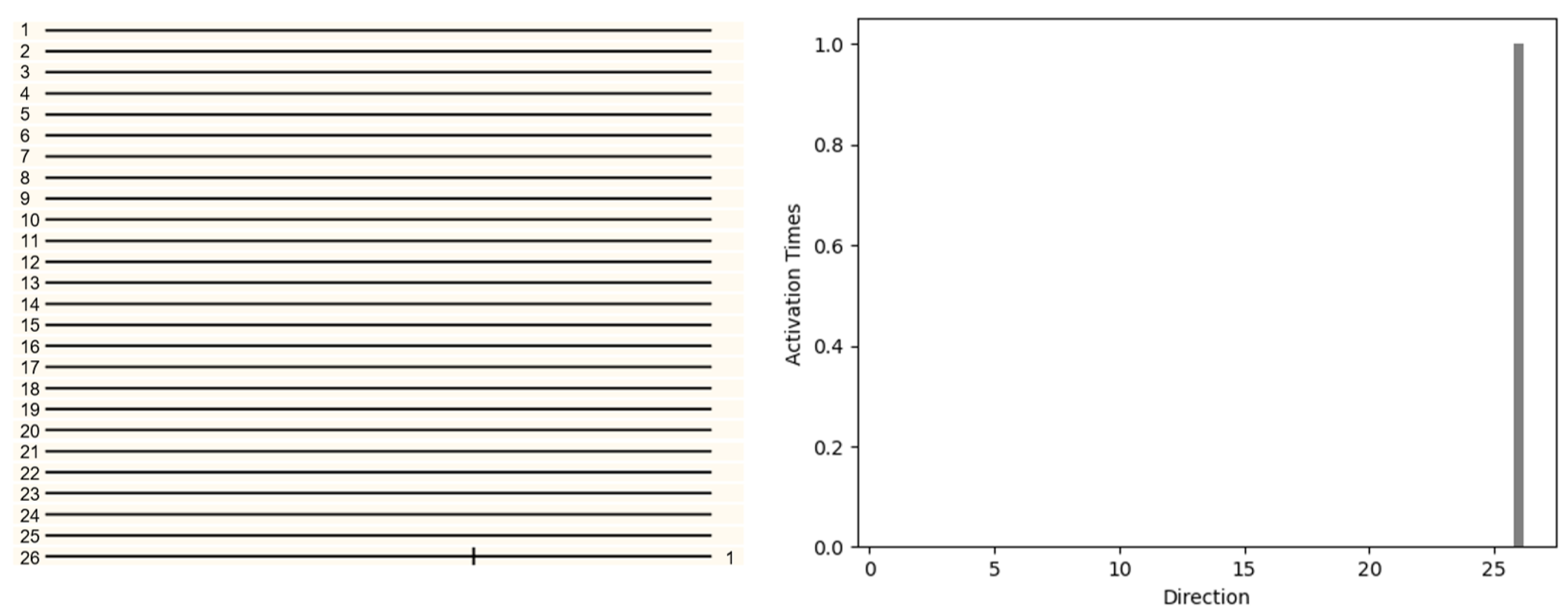
First, in the three dimensional space, consider a single voxel object moving in direction 26 (1,1,1) in
Figure 9. The object will be projected on the left and right retinas respectively. Local direction selective neurons will receive information from the retina and determine the direction (LFDN Layer). Then all the information of LFDN Layer will be analyzed by GFDN layer. GFDN layer will count all activations in each direction and determine the final motion direction. The pattern with only one voxel was displaced 1 unit along the x,y,z direction. The 26 local direction detective retinal ganglion neurons were used to detect the motion direction and the result is shown in
Figure 9. The responses of the 26 local direction detective retinal ganglion neurons were obtained by spatially convolving 26 local direction detective retinal ganglion neurons over the three dimensional image at time t (after moving) and reacting with the delayed two-dimensional image at time t −
t (before moving) (in this simulation, the reaction was a logical AND operation of a voxel of the region at time t and the adjacent voxel at t −
t in the particular direction). The activities of the twenty-six local direction detective retinal ganglion neurons were recorded (
Figure 9), of which only the UPWARD neuron was activated. We can also find that there is activation in only one direction in the histogram. We can infer the direction of object movement from the picture.
The same result is also applicable to complex voxels. In
Figure 10, the pattern with only four voxels is displaced −1 unit along the x direction and 1 unit along the y,z direction. In
Figure 10, direction 9 (−1,1,1) is activated. We counted the number of activations in each direction and drew a histogram
Figure 9. It can be seen that the neurons of direction 9 (−1,1,1) activate most, from which can be inferred that the object moves in direction 9 (−1,1,1).
In
Figure 11, the pattern with only sixteen voxels is displaced 1 unit along the y,z direction. We counted the number of activations in each direction and drew a histogram
Figure 10. It can be easily seen that the number of activations in direction 17 (0,1,1) is the most, from which it can be inferred that the object is moving in direction 17 (0,1,1).
In recent years, Convolutional Neuron Network (CNN) has attracted great attention from researchers [
37,
38,
39], including in the field of human computer interaction. To verify the accuracy of our proposed mechanism, we compare it with CNN-based methods. Its structure is shown in the
Figure 12. There were five layers in the CNN that we used: (i) A convolutional layer with convolution kernels (3 × 3) and 16 feature maps; (ii) A pooling layer with max pooling and a pooling size of (2,2); (iii) A convolutional layer with convolution kernels (3 × 3) and 32 feature maps; (iv) Another pooling layer with max pooling and a pooling size is of (2,2); (v) A fully connected layer with 26 outputs.
The CNN in this experiment uses (i) Rectified Linear Unit (ReLU) as the activation function; (ii) Adamoptimizer with a learning rate of 0.02 as the optimizer; (iii) Softmax cross entropy as the cost function.
We use the projected left and right retina maps as the training set of CNN which contains 2 × 10,000 images and we use 70% of them as the training set, the other 30%of them are testing set. Each of these images above contains eight voxels and no noise voxel.
To make the experiment more convincing, we added noise to the image. To describe the amount of noise we add more precisely. We assume that the volume of the object (measured in voxels) is Vo, and we assume that the volumetric cumulative sum of the noise (measured in voxels) is Vn. We define the noise object ratio as follows:
In
Table 2, we can see that AVS achieves nearly 100% accuracy when there is no noise voxel which is equal to CNN. We then add 50% noise voxels to the testing set (Noise Ratio = 50%), CNN’s identification accuracy drops quickly to 87.45%, and the accuracy of the proposed mechanism remains at 100%, which is better than CNN. If we add 50% noise to the testing set (Noise Ratio = 50%), the accuracy of proposed mechanism 100% is still better than CNN 99.3%. Until we increase the noise by 200%(Noise Ratio = 200%), the accuracy of our method retains 100% accuracy, and CNN is almost undetectable which at 33.7%. In
Table 2, it can be inferred that the proposed mechanism shows superior noise resistance. In
Table 3, the result is not much different from
Table 2. We then increase the object voxels to 32 in
Table 4. Our proposed mechanism has a good accuracy 99.8% when it increases to 1600% (Noise Ratio = 1600%) while the accuracy of CNN has dropped to 9%.
Compared with CNN, the proposed mechanism shows better performance in the presence of noise and operates more efficiently. Furthermore, the proposed mechanism is more similar to the biological model. Using 1660Ti GPU, CNN needs a lot of training data and costs about 0.5–1 h to train, while the proposed mechanism does not need pre-training and only takes less than 2 s to finish the test. Compared with latest methods [
31,
32,
33,
34,
35], these methods only focus on two dimensional cases. None of these studies took into account that humans have two eyes, nor did they figure out how the human eye perceives the three dimensional motion direction, which could only deal with the direction and speed of two-dimensional motion. The proposed mechanism explains how local three dimensional direction detection neurons extract the three dimensional motion direction.
5. Conclusions
In this paper, we have presented a three dimensional artificial visual system to provide a systemic explication of motion direction detection in three dimensional space. We propose the three dimensional direction detective neuron, which can be realized by a logic AND operation. With a local receptive field, these neurons can extract elementary visual features. These features are then analyzed by the subsequent layers in order to detect higher-order features, for example, the global motion direction. We carry out several computer simulations to demonstrate the validity of the mechanism. Compared to previous studies, this mechanism explains how direction-detection neurons analyse the motion of three dimensional objects. At the same time, our research also suffers some shortcomings and limitations. Although its resistance to noise is better than CNN, if a certain anti-noise processing is performed, the experimental results will be better. At the same time, it cannot measure the speed of objects, which is in our future work. The mechanism can be used as a frame for understanding many other basic phenomena such as the perception of motion direction, moving speed, orientation, binocular vision. The mechanism also gives a guidance for visual computation in the visual cortex and explains how visual input is fragmented and reassembled at different stages of the visual system and how function is divided across different elements of the visual circuit. The mechanism can also help us to understand how other sensor systems works, such as olfaction, taste, and touch, are encoded at the cortical circuit level.


