


Development of Manipulator Digital Twin Experimental Platform Based on RCP

Abstract
:1. Introduction
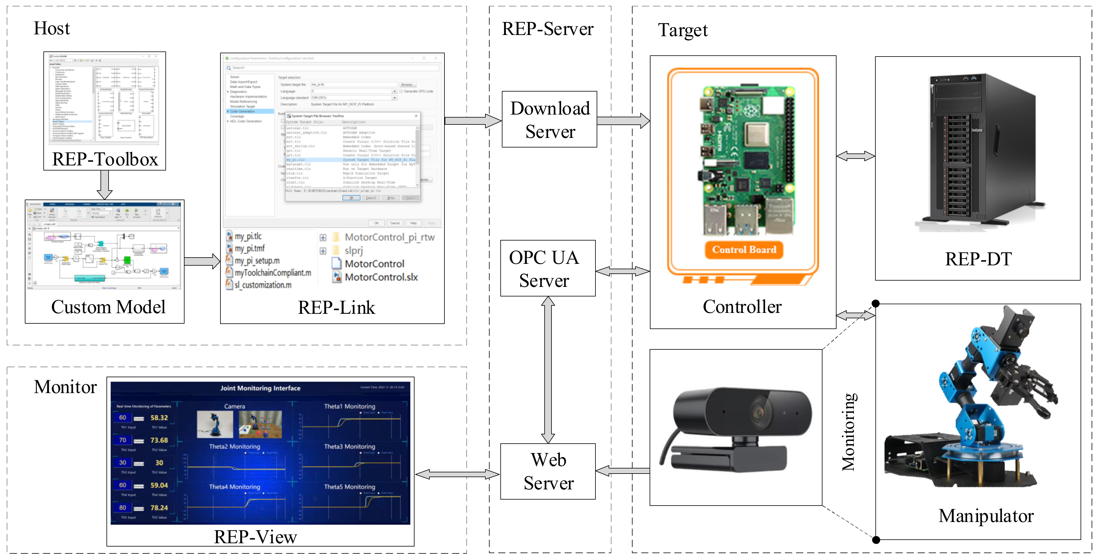
2. Overall System Design
3. Remote Experiment Platform Design
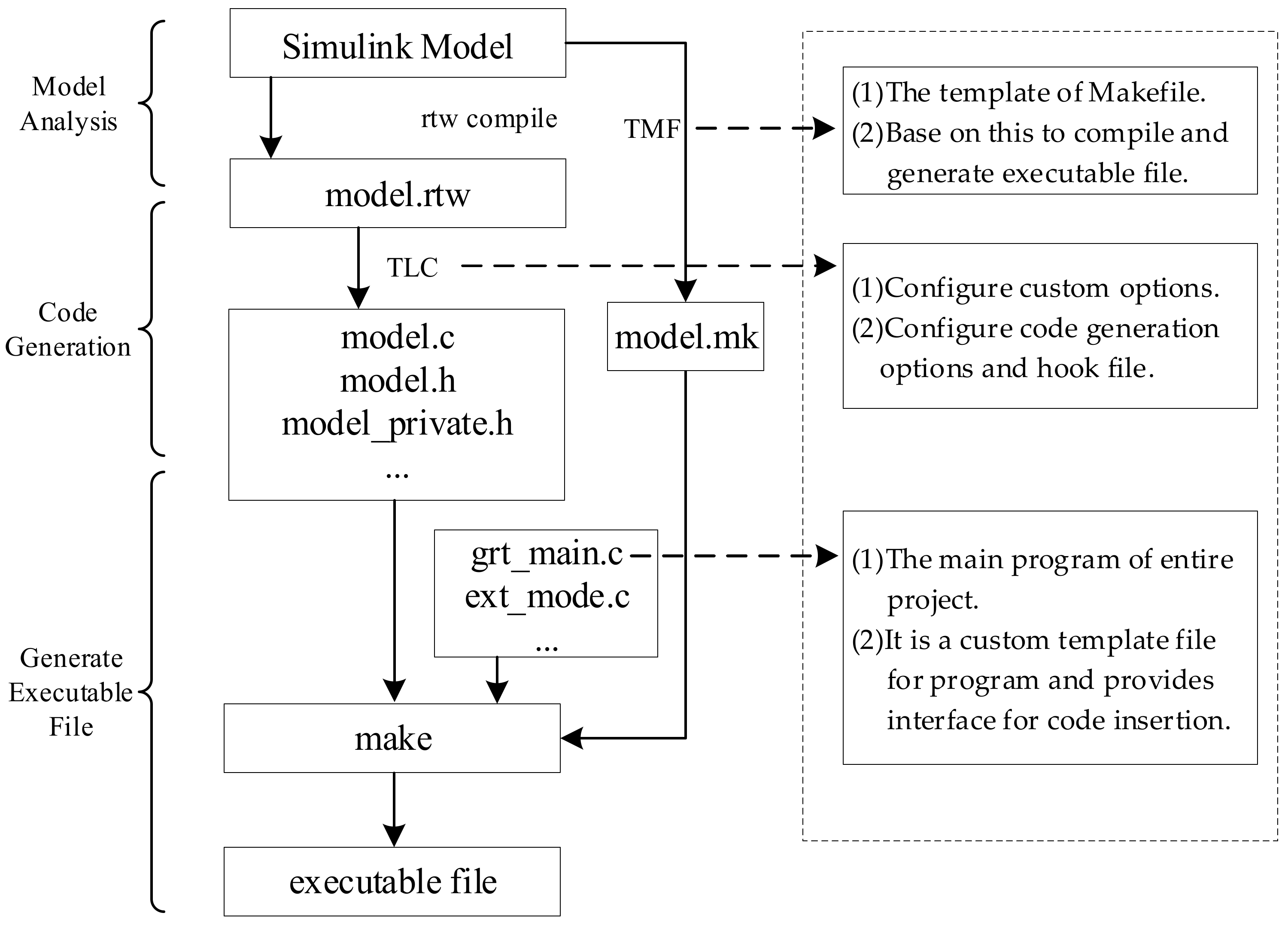
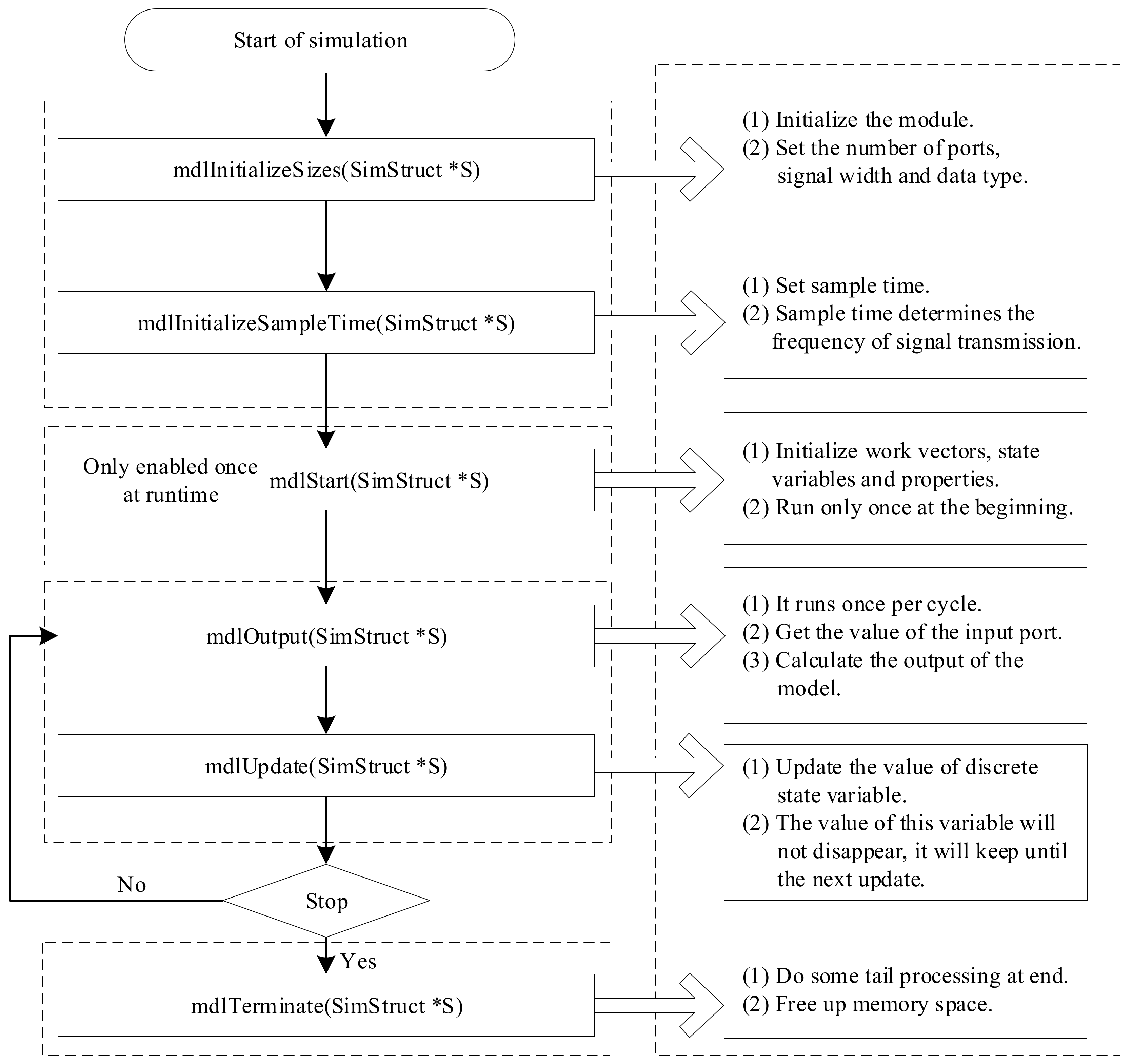
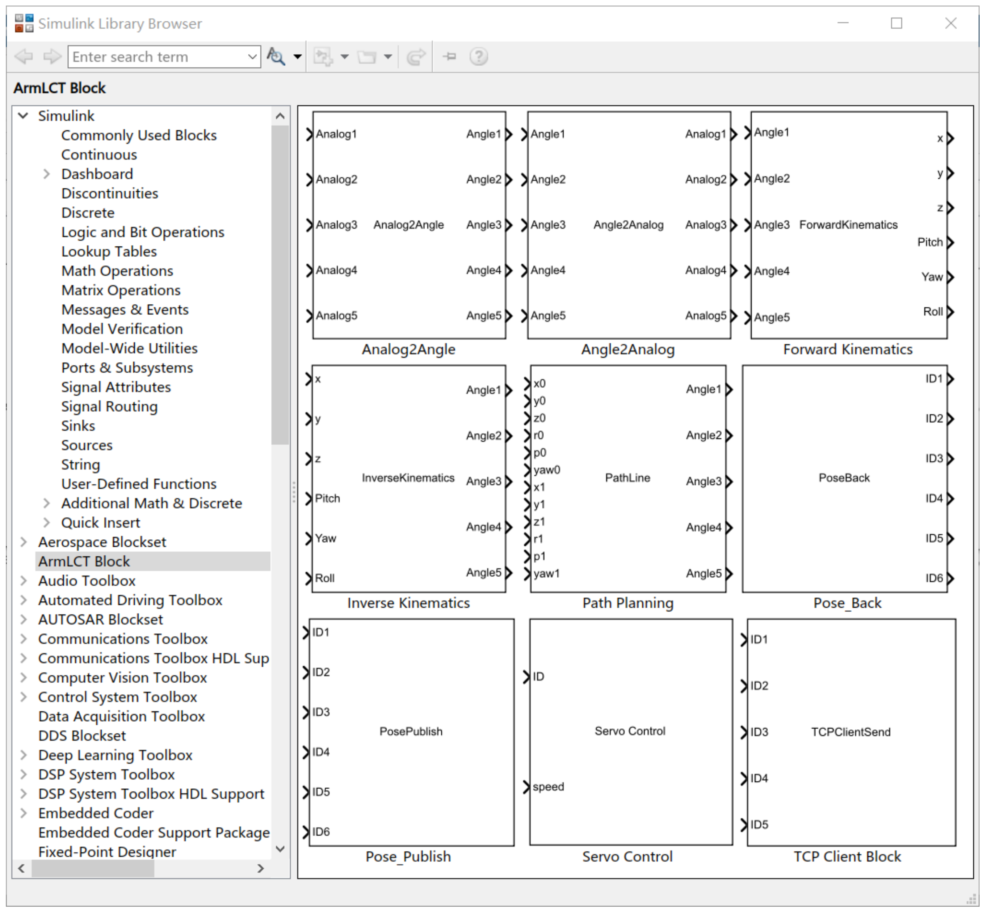
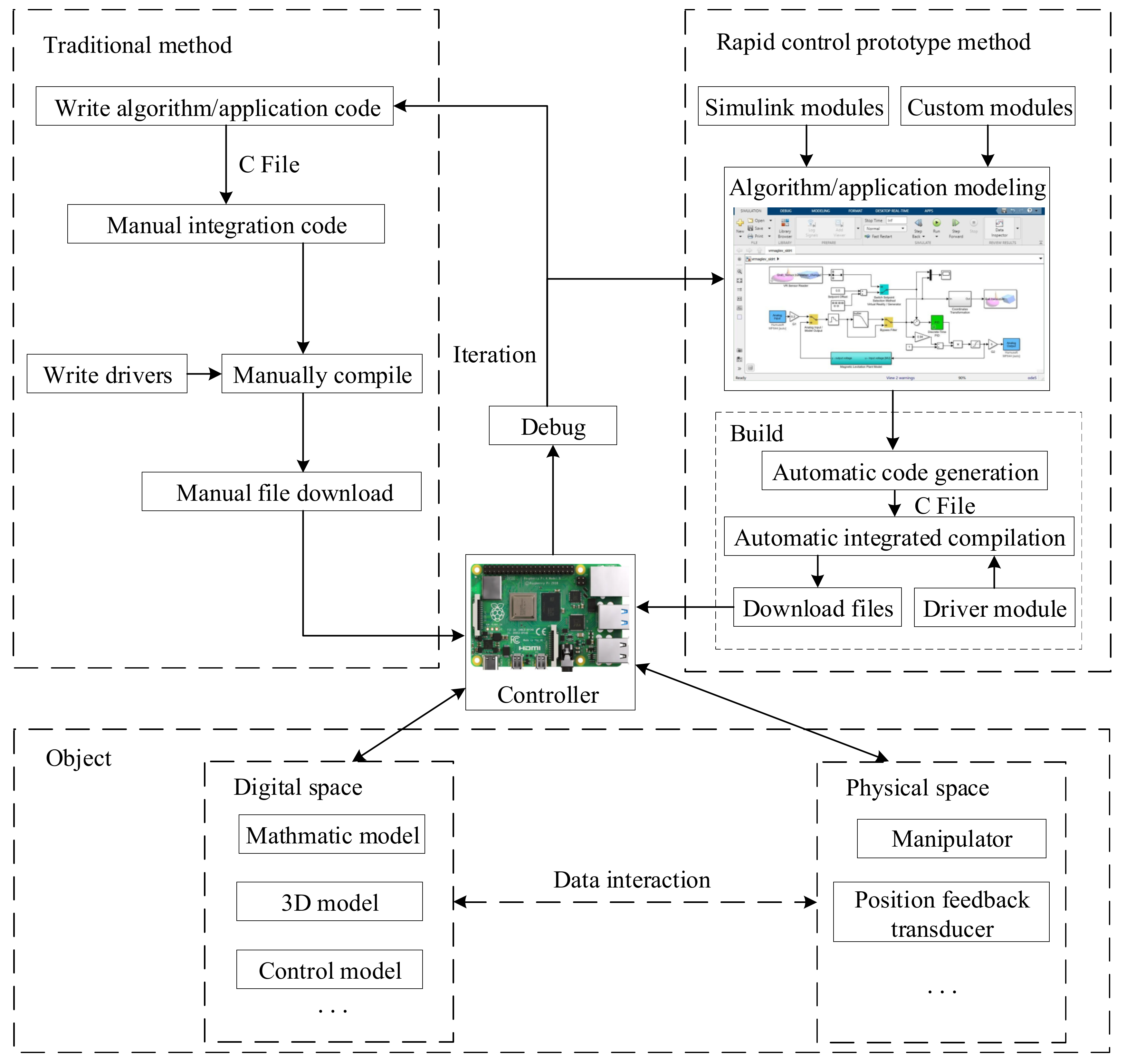
3.1. Design and Implementation of the Rapid Control Prototype System
- (1)
- Compiler, header files, and related library file paths.
- (2)
- Compiler optimization options and libraries required for linking.
- (3)
- Compilation rules
- (4)
- External mode
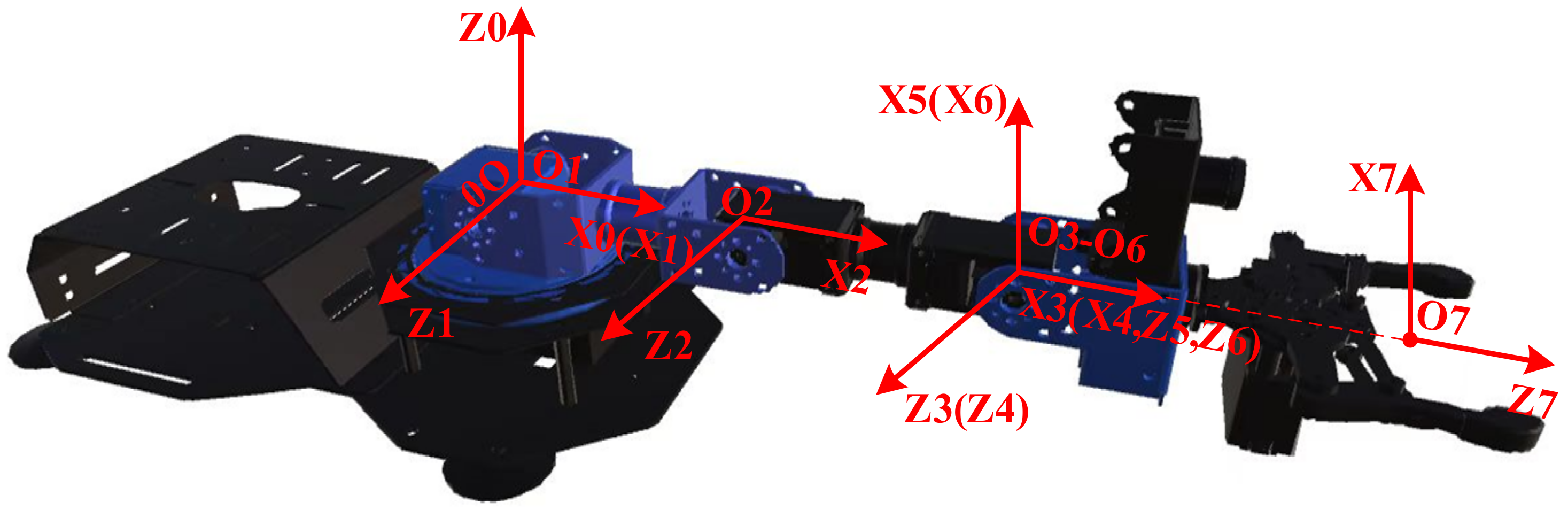
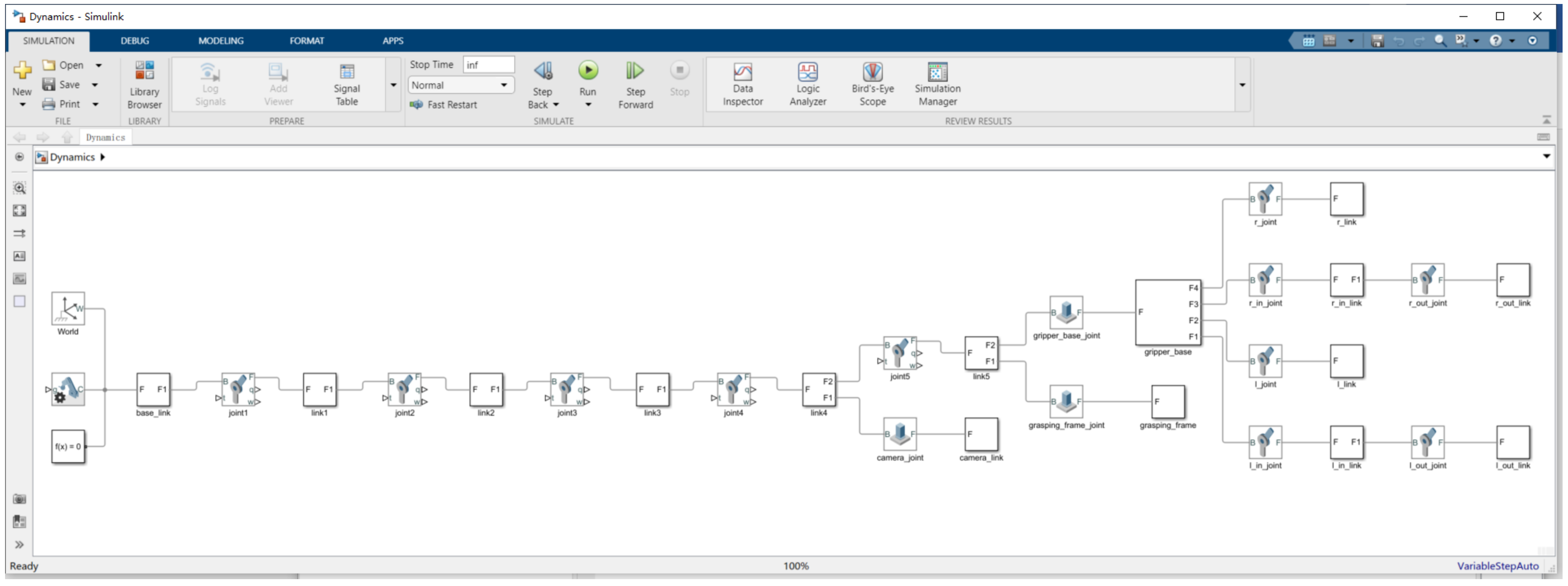
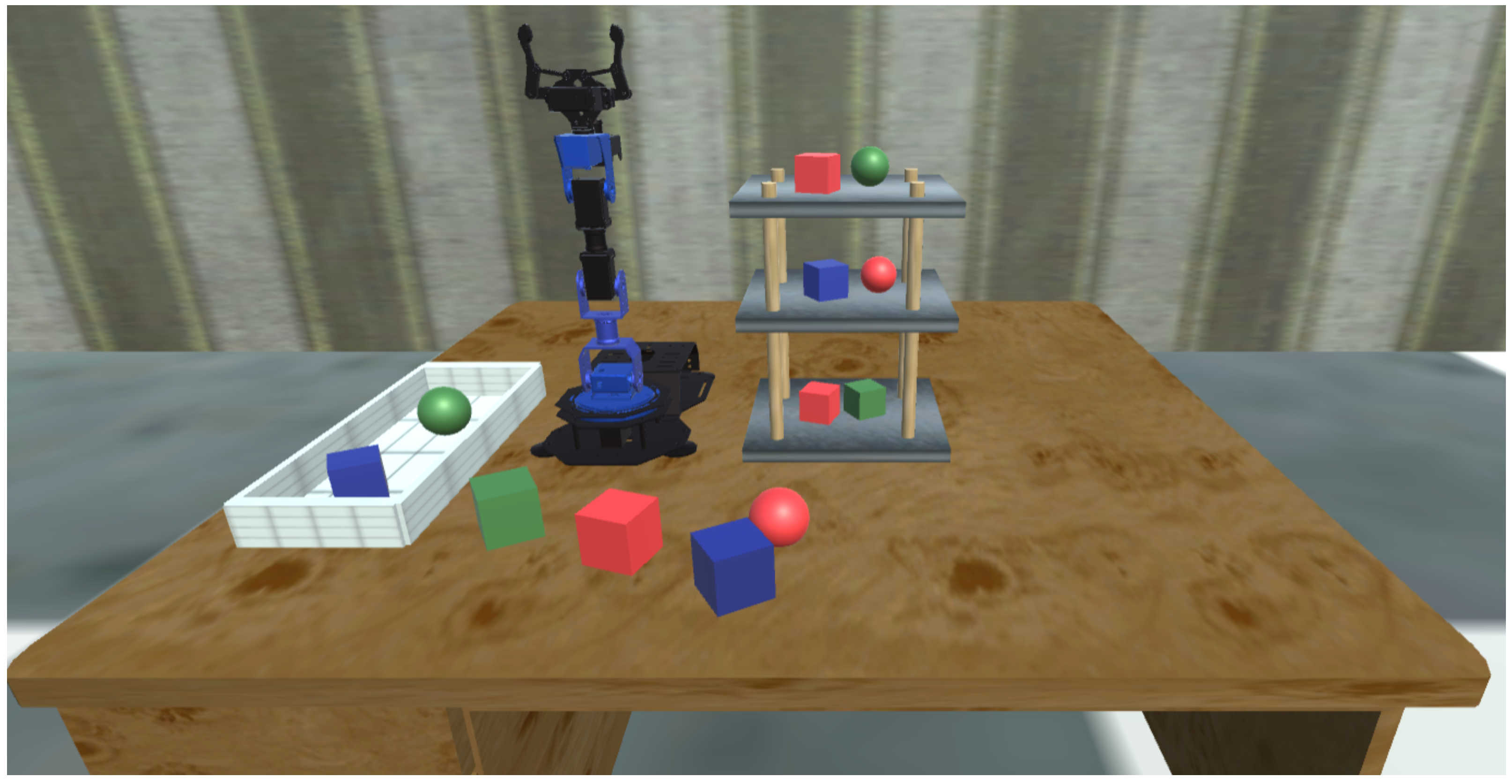
3.2. Design and Implementation of Digital Twinning
- di: Offset along previous z to the common normal;
- θi: Angle about previous z, from old x to new x;
- ai: Length of the common normal;
- αi: Angle about common normal, from old z axis to new z axis.
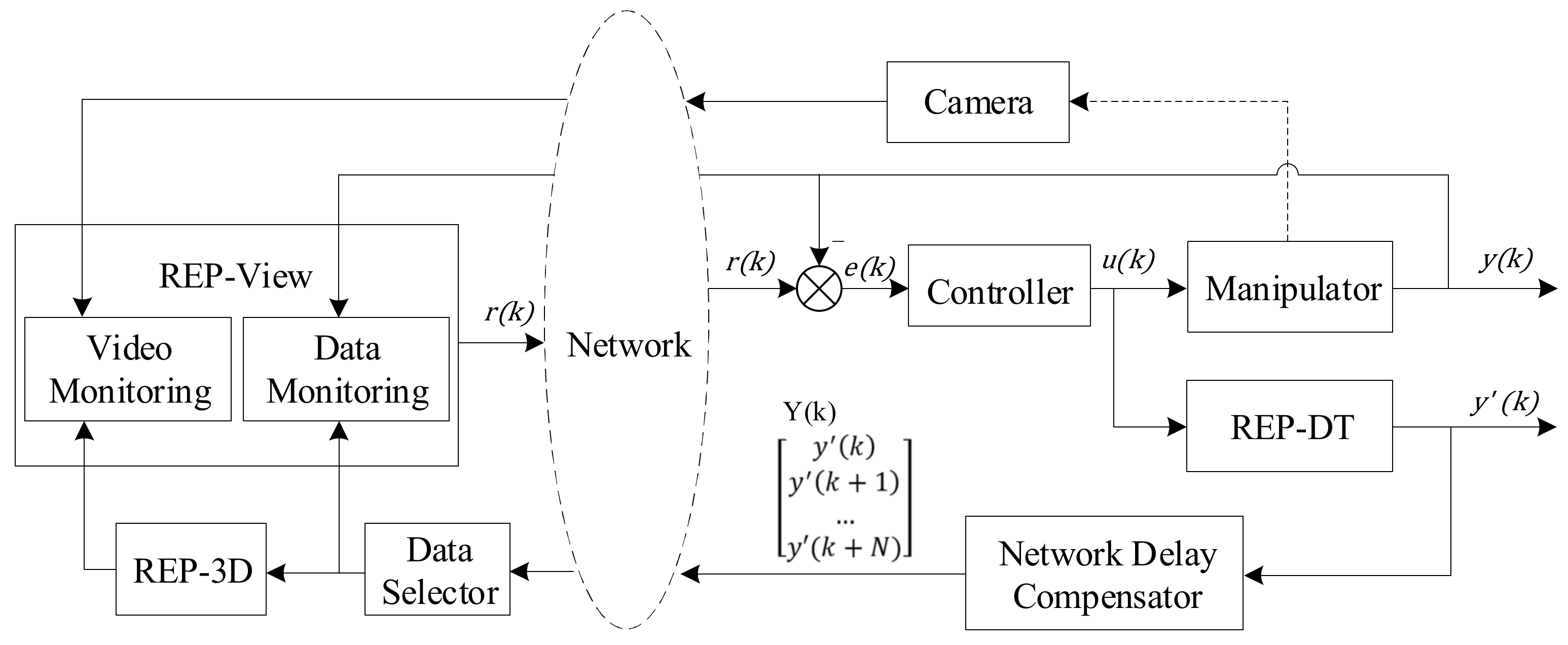
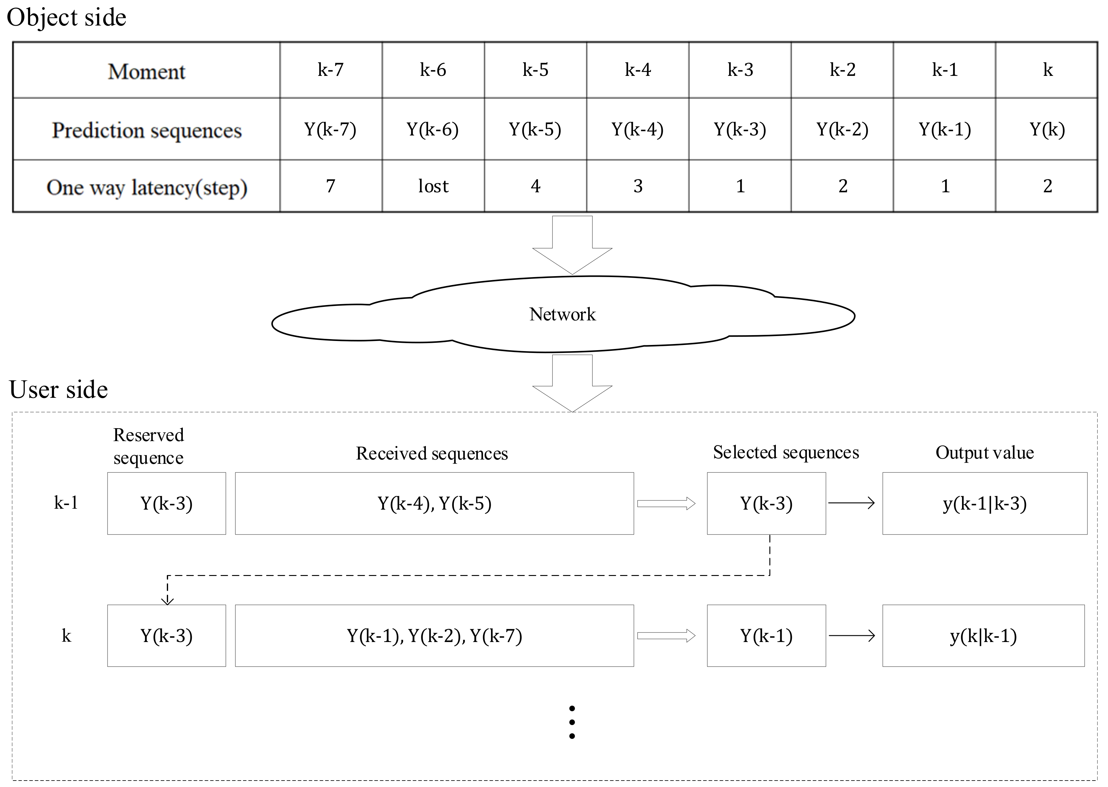
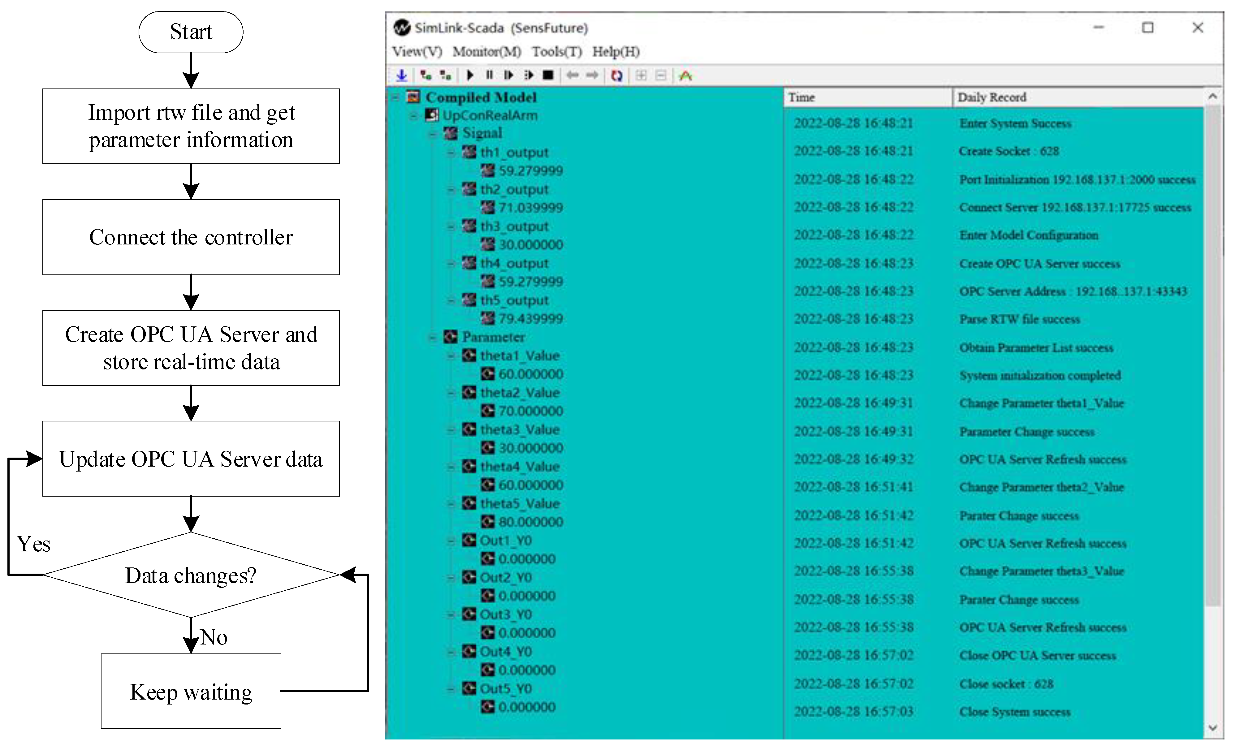
3.3. Design and Implementation of Data Monitoring
3.4. Design and Implementation of Video Monitoring
4. RCP Experimental Method and Case Study of PID Control
4.1. RCP Method Compared with Traditional Methods
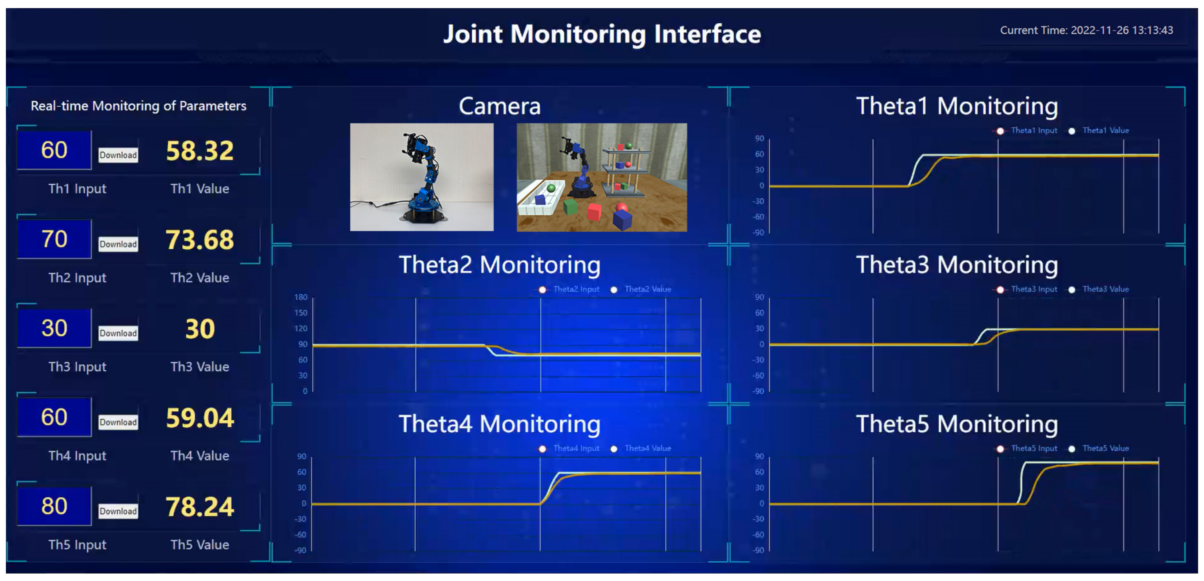
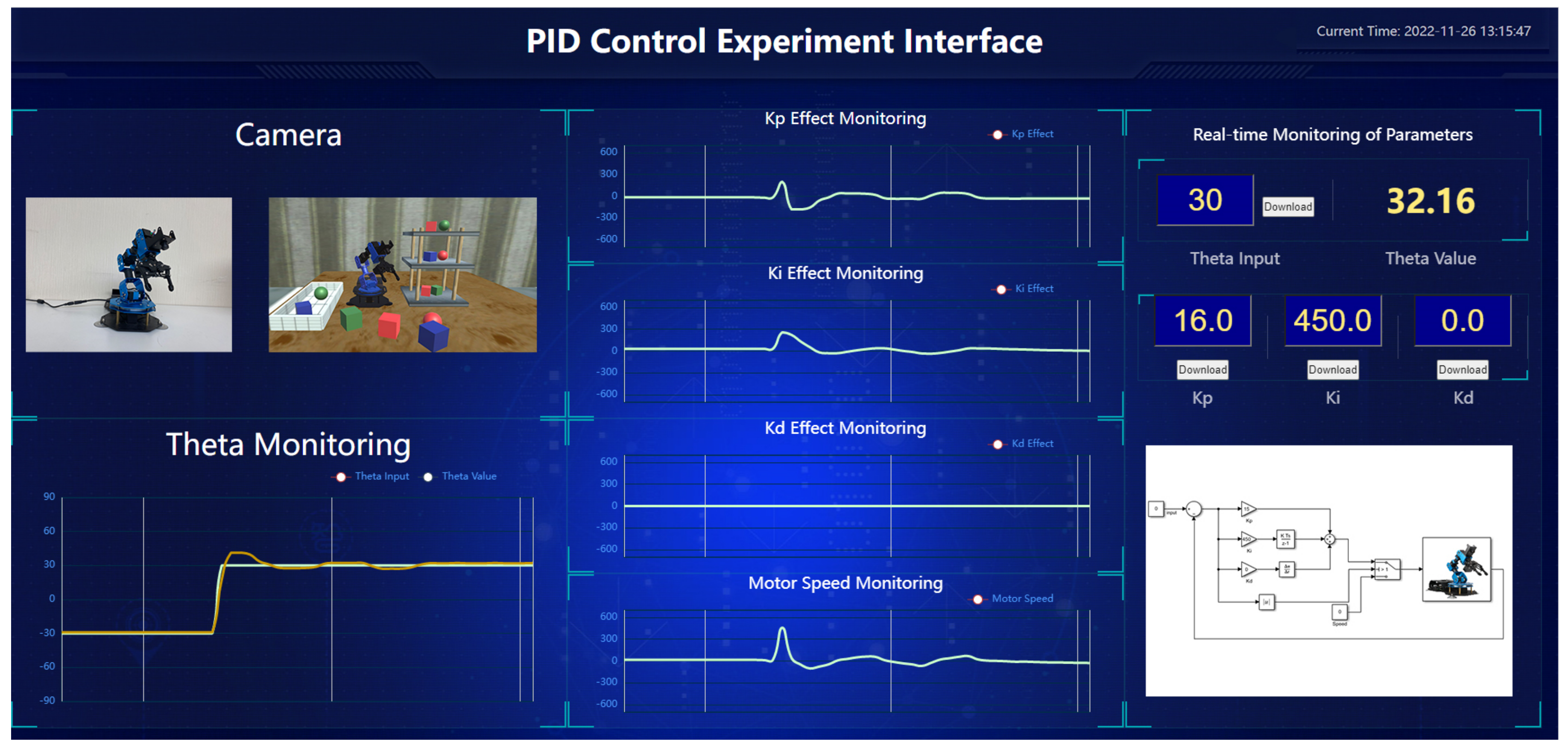
4.2. PID Control Experiment with the Platform
5. Conclusions
Author Contributions
Funding
Institutional Review Board Statement
Informed Consent Statement
Data Availability Statement
Conflicts of Interest
References
- Li, Z. The Reform and Innovation of Chemistry Classroom Teaching Mode in the Era of Big Data. In Proceedings of the 2017 9th International Conference on Measuring Technology and Mechatronics Automation (ICMTMA), Changsha, China, 14–15 January 2017; pp. 417–421. [Google Scholar]
- Tang, C.; Lin, H.; Zhang, L.; Bao, T.; Zhang, Y.; Liu, Z. Electrical and Electronic Experiment Platform Teaching Method with Remote Control. In Proceedings of the 2020 IEEE International Conference on Signal Processing, Communications and Computing (ICSPCC), Macau, China, 21–24 August 2020; pp. 1–6. [Google Scholar]
- Wang, S.; Zhang, F.; Tang, Q.; Zhang, X.; Zhao, R. A Take-Home Motor Control Teaching Experiment Platform for Control Engineering-Related Courses. IEEE Trans. Educ. 2022, 65, 115–123. [Google Scholar] [CrossRef]
- Zhai, J.M.; Xu, X. Development of a web-based remote experiment system for engineering curricula. In Proceedings of the 2011 IEEE International Symposium on IT in Medicine and Education, Guangzhou, China, 9–11 December 2011; Volume 1, pp. 469–472. [Google Scholar]
- Li, G. Research on the Importance of the Basic Experiment Based on the Experimental Platform. In Proceedings of the 2016 International Conference on Robots & Intelligent System (ICRIS), Zhangjiajie, China, 27–28 August 2016; pp. 384–386. [Google Scholar]
- Megalingam, R.K.; Vivek, G.V.; Bandyopadhyay, S.; Rahi, M.J. Robotic arm design, development and control for agriculture applications. In Proceedings of the 2017 4th International Conference on Advanced Computing and Communication Systems (ICACCS), Coimbatore, India, 6–7 January 2017; pp. 1–7. [Google Scholar]
- Lee, J.D.; Li, W.C.; Shen, J.H.; Chuang, C.W. Multi-robotic arms automated production line. In Proceedings of the 2018 4th International Conference on Control, Automation and Robotics (ICCAR), Auckland, New Zealand, 20–23 April 2018; pp. 26–30. [Google Scholar]
- Krasňanský, P.; Tóth, F.; Huertas, V.V.; Rohal’-Ilkiv, B. Basic laboratory experiments with an educational robotic arm. In Proceedings of the 2013 International Conference on Process Control (PC), Strbske Pleso, Slovakia, 18–21 June 2013; pp. 510–515. [Google Scholar]
- Bing, L.I.A.O.; Hongbin, Z.A.N.G.; Nana, Z.H.U.; Dongsheng, L.I.U.; Jiangmin, T.U.O.; Tao, H.E.; Lei, H.U.; Zheng, Y.A.N.G. System Design and Experiment of Bionics Robotic Arm with Humanoid Characteristics. In Proceedings of the 2018 WRC Symposium on Advanced Robotics and Automation (WRC SARA), Beijing, China, 16 August 2018; pp. 90–95. [Google Scholar]
- Jahnavi, K.; Sivraj, P. Teaching and learning robotic arm model. In Proceedings of the 2017 International Conference on Intelligent Computing, Instrumentation and Control Technologies (ICICICT), Kannur, Kerala, India, 6–7 July 2017; pp. 1570–1575. [Google Scholar]
- Rosen, R.; von Wichert, G.; Lo, G.; Bettenhausen, K.D. About The Importance of Autonomy and Digital Twins for the Future of Manufacturing. IFAC PapersOnLine 2015, 48, 567–572. [Google Scholar] [CrossRef]
- Wang, Z.; Gupta, R.; Han, K.; Wang, H.; Ganlath, A.; Ammar, N.; Tiwari, P. Mobility Digital Twin: Concept, Architecture, Case Study, and Future Challenges. IEEE Internet Things J. 2022, 9, 17452–17467. [Google Scholar] [CrossRef]
- Groshev, M.; Guimarães, C.; Martín-Pérez, J.; Oliva, A.D.L. Toward Intelligent Cyber-Physical Systems: Digital Twin Meets Artificial Intelligence. IEEE Commun. Mag. 2021, 59, 14–20. [Google Scholar] [CrossRef]
- Yin, Z.H.; Wang, L. Application and Development Prospect of Digital Twin Technology in Aerospace. IFAC PapersOnLine 2020, 53, 732–737. [Google Scholar] [CrossRef]
- Bratchikov, S.; Abdullin, A.; Demidova, G.L.; Lukichev, D.V. Development of Digital Twin for Robotic Arm. In Proceedings of the 2021 IEEE 19th International Power Electronics and Motion Control Conference (PEMC), Gliwice, Poland, 25–29 April 2021; pp. 717–723. [Google Scholar]
- Avila, E.A.; Chapa, D.P.; Arenas, I.D.; Hurtado, C.V. A Digital Twin implementation for Mobile and collaborative robot scenarios for teaching robotics based on Robot Operating System. In Proceedings of the 2022 IEEE Global Engineering Education Conference (EDUCON), Tunis, Tunisia, 28–31 March 2022; pp. 559–564. [Google Scholar]
- Hercog, D.; Curkovic, M.; Jezernik, K. DSP based rapid control prototyping systems for engineering education and research. In Proceedings of the 2006 IEEE Conference on Computer Aided Control System Design, 2006 IEEE International Conference on Control Applications, 2006 IEEE International Symposium on Intelligent Control, Munich, Germany, 4–6 October 2006; pp. 2292–2297. [Google Scholar]
- Werth, W.; Faller, L.; Liechtenecker, H.; Ungermanns, C. Low Cost Rapid Control Prototyping—A useful method in Control Engineering Education. In Proceedings of the 2020 43rd International Convention on Information, Communication and Electronic Technology (MIPRO), Opatija, Croatia, 28 September–2 October 2020; pp. 711–715. [Google Scholar]
- Dong, W.; Zhang, X.; Jing, L.; Wu, W. Design of Rapid-control-prototype Platform for Modular Multilevel Converter Based on RT-lab. In Proceedings of the 2019 IEEE 10th International Symposium on Power Electronics for Distributed Generation Systems (PEDG), Xi’an, China, 3–6 June 2019; pp. 94–98. [Google Scholar]
- Michael, T.; Reynolds, S.; Woolford, T. Designing a Generic, Software-Defined Multimode Radar Simulator for FPGAs Using Simulink® HDL Coder and Speedgoat Real-Time Hardware. In Proceedings of the 2018 International Conference on Radar (RADAR), Brisbane, Australia, 27–31 August 2018; pp. 1–4. [Google Scholar]
- Milam, W.P. A distributed computing approach to rapid prototyping for embedded controllers. In Proceedings of the 36th Midwest Symposium on Circuits and Systems, Detroit, MI, USA, 16–18 August 1993; Volume 2, pp. 1155–1158. [Google Scholar]
- Zhong, Q.C.; Matthews, C.; Nguyen, P.L.; Clarke, S. Low-cost Rapid Control Prototyping paradigm. In Proceedings of the UKACC International Conference on Control 2010, Coventry, UK, 7–10 September 2010; pp. 1–5. [Google Scholar]
- Zhao, Y.; Liu, Z.; Yang, W.; Cai, L. Rapid Control Prototyping of an Automated Clutch Using dSPACE and Matlab/Simulink. In Proceedings of the 2010 International Conference on Computing, Control and Industrial Engineering, Wuhan, China, 5–6 June 2010; Volume 1, pp. 221–226. [Google Scholar]


| i | θi | di | ai | αi |
|---|---|---|---|---|
| 1 | 0 | 0 | 0 | 90 |
| 2 | 0 | 0 | 0.09736 | 0 |
| 3 | 0 | 0 | 0.09255 | 0 |
| 4 | 90 | 0 | 0 | 90 |
| 5 | 0 | 0.05556 | 0 | 0 |
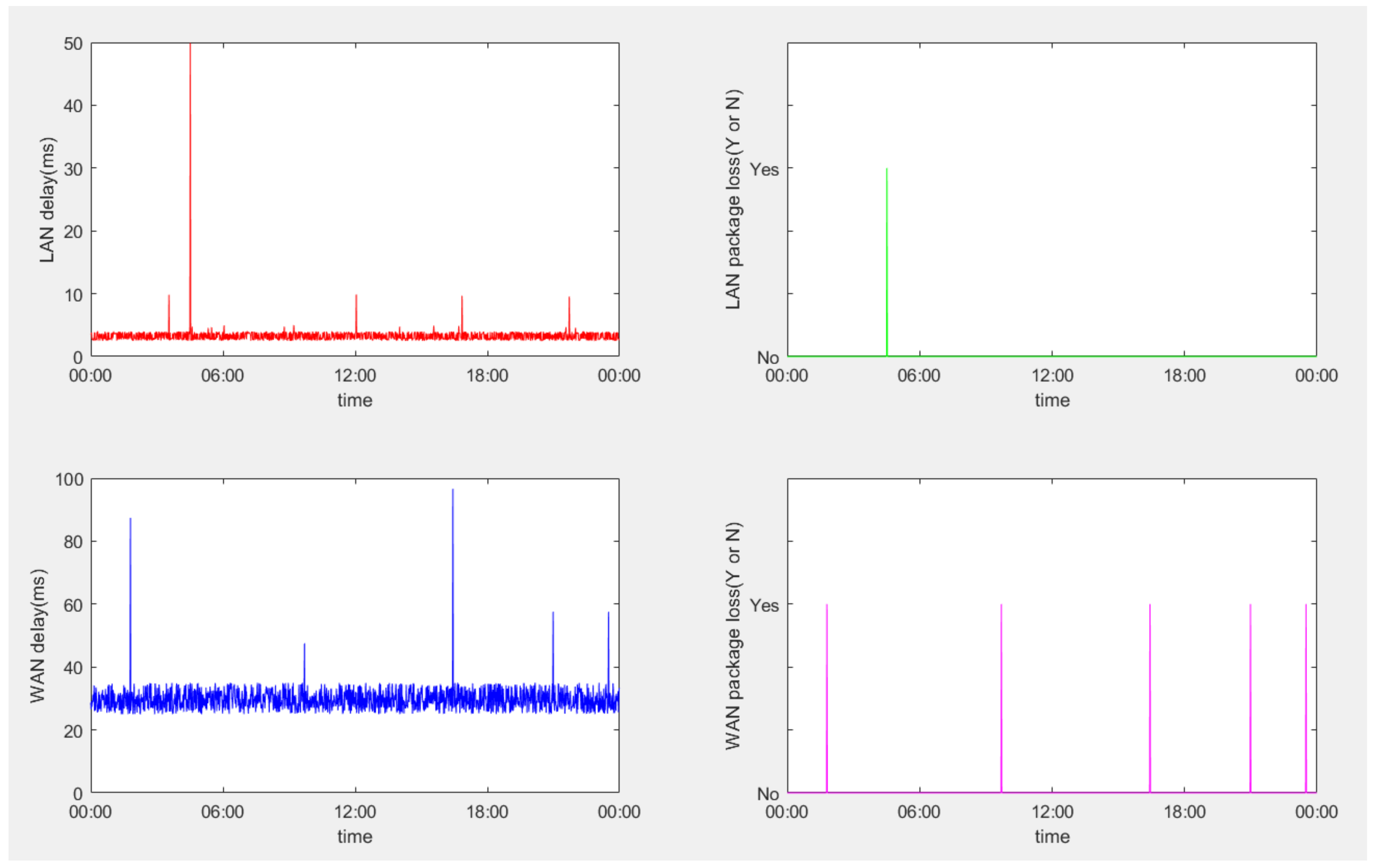
| Min RTT Latency (ms) | Max RTT Latency (ms) | Average RTT Latency (ms) | Loss Rate (%) | |
|---|---|---|---|---|
| LAN | 2.5 | 49.9 | 3.3 | 0.07% |
| WAN | 25.0 | 96.6 | 29.9 | 0.35% |
Publisher’s Note: MDPI stays neutral with regard to jurisdictional claims in published maps and institutional affiliations. |
© 2022 by the authors. Licensee MDPI, Basel, Switzerland. This article is an open access article distributed under the terms and conditions of the Creative Commons Attribution (CC BY) license (https://creativecommons.org/licenses/by/4.0/).
Share and Cite
Dong, Z.; Han, X.; Shi, Y.; Zhai, W.; Luo, S. Development of Manipulator Digital Twin Experimental Platform Based on RCP. Electronics 2022, 11, 4196. https://doi.org/10.3390/electronics11244196
Dong Z, Han X, Shi Y, Zhai W, Luo S. Development of Manipulator Digital Twin Experimental Platform Based on RCP. Electronics. 2022; 11(24):4196. https://doi.org/10.3390/electronics11244196
Chicago/Turabian StyleDong, Zhe, Xiaoyao Han, Yuntao Shi, Weifeng Zhai, and Song Luo. 2022. "Development of Manipulator Digital Twin Experimental Platform Based on RCP" Electronics 11, no. 24: 4196. https://doi.org/10.3390/electronics11244196
APA StyleDong, Z., Han, X., Shi, Y., Zhai, W., & Luo, S. (2022). Development of Manipulator Digital Twin Experimental Platform Based on RCP. Electronics, 11(24), 4196. https://doi.org/10.3390/electronics11244196