Communication

Preliminary Study of a G-Band Extended Interaction Oscillator Operating in the TM31-3π Mode Driven by Pseudospark-Sourced Multiple Electron Beams

The Terahertz Science and Technology Key Laboratory of Sichuan Province, School of Electronic Science and Engineering, University of Electronic Science and Technology of China, Chengdu 610054, China
*
Author to whom correspondence should be addressed.
Electronics 2022, 11(23), 3961; https://doi.org/10.3390/electronics11233961
Submission received: 20 October 2022 / Revised: 25 November 2022 / Accepted: 26 November 2022 / Published: 29 November 2022
(This article belongs to the Section Electronic Materials)

Abstract

:
This paper presents the first design that combines pseudospark-sourced (PS) electron beams with a multiple-beam extended interaction oscillator (EIO). The PS electron beam is an excellent choice for driving EIOs because it has high current density and does not require a focusing magnetic field. The EIO with coaxial structure adopts the method of multiple electron beams, which plays a crucial role in improving the average output power. At the same frequency, the EIO operating in the high-order TM31-3π mode has a larger cavity size than the EIO operating in the traditional TM01-2π mode. The high-order TM31-3π mode solves the problem of the EIO’s manufacture at high frequency. In order to verify the above points, a G-band PS multiple-beam EIO operating in TM31-3π mode has been designed. The beam–wave interaction particle-in-cell simulation results show that the EIO’s peak output power is 39.2 kW at 217 GHz, and that its efficiency is around 6.1%. The EIO with six pencil beams operates at a voltage of 43 kV. The total current of the six electron beams is 15 A (equally distributed among the six beams), and the corresponding current density is about 5000 A/cm2. Considering the ohmic loss and the effect of skin depth, the conductivity used in these simulations is 2 × 10⁷ S/m. The design is an excellent way to improve the output power of EIO operating at high frequency.

1. Introduction

In recent years, the main research has focused on powerful and reliable electromagnetic radiation sources ranging from millimeter-wave (MMW) to terahertz (THz). These radiation sources have a wide range of applications in military and daily life, such as the identification of security threats, air warning systems, molecular spectroscopy, biomedicine diagnostics, and high-data-rate communication [1,2,3,4,5,6]. Compared to conventional semiconductor devices, the vacuum electronic devices (VEDs), including extended interaction klystrons (EIKs) and EIOs, offer a higher output power and are more robust [7]. The EIOs have the traveling wave tubes’ advantages of wide bandwidth and the klystrons’ ability to generate high power [8]. Under the same beam parameters, the EIO has a higher unity gain than traditional coupled-cavity klystrons and traveling wave tubes, which greatly reduces the total length of the interaction circuit and makes the structure compact [9]. Because of these excellent characteristics, the EIOs are widely used as the compact, high-power MMW and THz sources.
The increasing operating frequency of the EIO means the device is very small, which leads to a significant drop in the input current of the EIO under the same current density. The electron beams with particularly high current density and precisely focused power are crucial to EIOs operating at high frequency. In the design, the authors use six PS electron beams instead of the traditional thermionic cathode system. The PS discharge is a self-focusing and transitory gas discharge, and it can be produced at a lower gas pressure (generally 1–80 Pa). The PS electron beam has a wide range of applications in several fields, such as high-intensity X-rays, extreme ultraviolet sources, etc. [10,11]. Compared to the thermionic cathode electron beam, the PS electron beam has many merits, including high current density and brightness, no need for a guiding magnetic field, and a low vacuum requirement [12]. The University of Strathclyde carried out the simulations and experiments of EIOs based on the PS electron beam. In the simulations, the output power of the W-band pencil beam EIO is 5.6 kW, and the output power of the G-band sheet beam EIO is 2.1 kW [13].
In addition to using a PS electron beam to improve the current density, the total input current can also be increased by using multiple beams. The multiple-beam EIO with a coaxial structure has a large cross-sectional area of EIO electron beams, which further increases the input current and makes the beam–wave interaction more efficient. The multiple-beam EIO based on PS electron beams proposed in this paper operates in the TM31-3π mode. For the same EIO cavity, the operating frequency of the high-order mode is higher than the operating frequency of the fundamental mode. In other words, the volume of the EIO cavity operating in the high-order mode is greater than that of the EIO cavity operating in the fundamental mode at the same frequency. The use of TM31 mode further increases the cross-sectional area of the EIO electron beams, and also reduces the fabrication difficulty. At the same time, the use of 3π mode instead of 2π mode helps increase the Z direction dimension of the device under the same operating voltage.
An original EIO operating at 217 GHz based on PS multiple electron beams is proposed. In the design, the PS electron beams’ characteristics—high current density and no need for external magnetic field—are fully utilized; the large structure size of the EIO operating in TM31-3π mode is also an advantage. It is an effective way to generate high-power MMW and THz radiation sources. The paper is organized as follows: Section 2 introduces the PS multiple electron beam EIO; Section 3 is the preliminary study of the TM31-3π mode; and Section 4 is the PIC simulation results of the PS multiple electron beam EIO operating in TM31-3π mode. The conclusions are in Section 5.

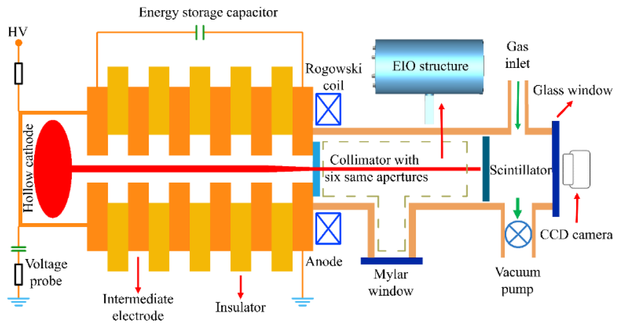
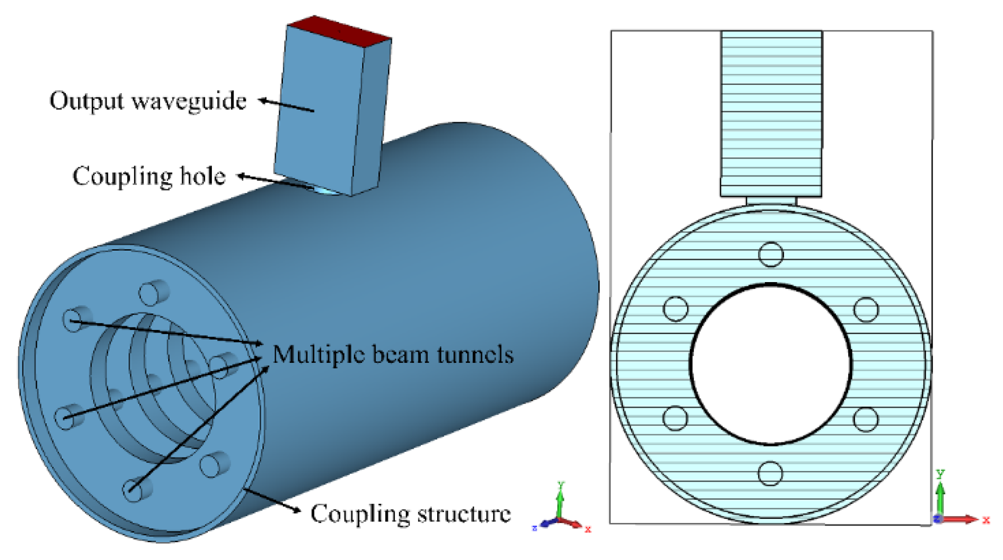
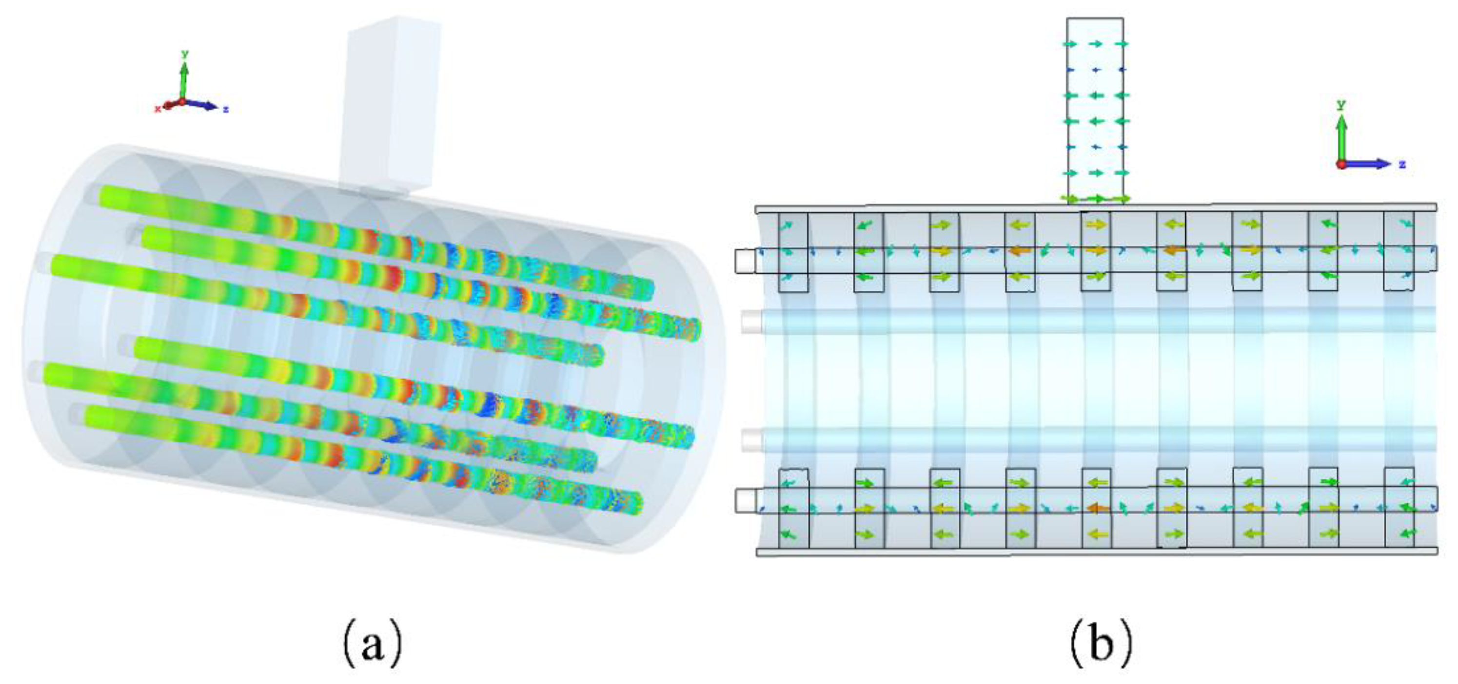
2. PS Multiple Electron Beam EIO with Coaxial Structure

Relatively high current density is attractive for extended interaction devices operating in MMW and even THz ranges [14]. The PS electron beams are widely applied in microwave radiation sources because they do not require an external magnetic field and have high current density [13]. The PS discharge belongs to the instantaneous gas discharge in relatively low air pressure. The current density generated by the PS discharge can reach up to 104 A/cm2, and its current rise rate can even reach an astonishing 1012 A/s [8,15,16]. A 100A PS electron beam pulse signal was measured in the experiment without an additional magnetic field. At the beginning of the discharge, an initial beam of electrons with ultra-high energy is emitted into the background gas. The original electrons ionize the surrounding gas, creating a plasma channel. The electrons are all negatively charged, so there is a repulsive force between them, causing a steady stream of electrons emitted from the cathode to expel electrons in the plasma. Meanwhile, the ions remain relatively stationary because of their greater mass. The resulting ion channel can be used to focus the electron beam, so that the PS discharge does not need an external magnetic field. By changing the PS electron emission apertures, the emitted electron beams are matched with different beam tunnels of EIOs, such as pencil beam, sheet beam, and multiple-beam.
Figure 1 illustrates the experimental device used to study the discharge characteristics of the PS electron beam. As shown in Figure 1, the left half is the PS discharge system, and the right half is the EIO device. The intermediate electrodes are interspersed with the insulators to form a five-gap PS discharge setup. The PS electron discharge section includes a hollow cathode, a voltage probe, an anode, and an external energy storage capacitor. The additional high-voltage capacitor needs to be added between the cathode and the anode to provide the discharge energy because the self-capacitance between them is relatively low. At the beginning, a vacuum pump reduces the air pressure in the setup to a relatively small value. A mechanical needle valve controls the gas inlet, and the working gas is slowly injected. The gas pressure value in the device is kept in a stable state by the slow pumping of the vacuum pump. Then, the hollow cathode is connected to a high negative voltage, and the anode is grounded. After the discharge, the resulting PS electron beam is transmitted from the hollow cavity to the extended interaction circuit through a collimator. The collimator has six circular holes, each with a radius of 0.12 mm. These holes form multiple electron beams. A Rogowski coil, which surrounds the emitted PS electron beams, measures the total current of the electron beams. During the whole process, no external magnetic field is required.
The multiple-beam EIO with coaxial structure [17], as shown in Figure 2, operates in the G-band. The EIO includes two parts: the output structure and the slow-wave structure. A standard waveguide is connected to the middle of the coaxial structure through a circular hole. Nine identical coaxial cavities are connected to a hollow cylindrical coupling cavity to form a nine-gap interaction circuit. Six cylindrical beam tunnels intersect the coaxial cavities perpendicularly. Six pencil beams are distributed axisymmetrically in the coaxial structure. The radius of the six-beam tunnel, 0.13 mm, is slightly larger than the radius of the six circular holes on the collimator.

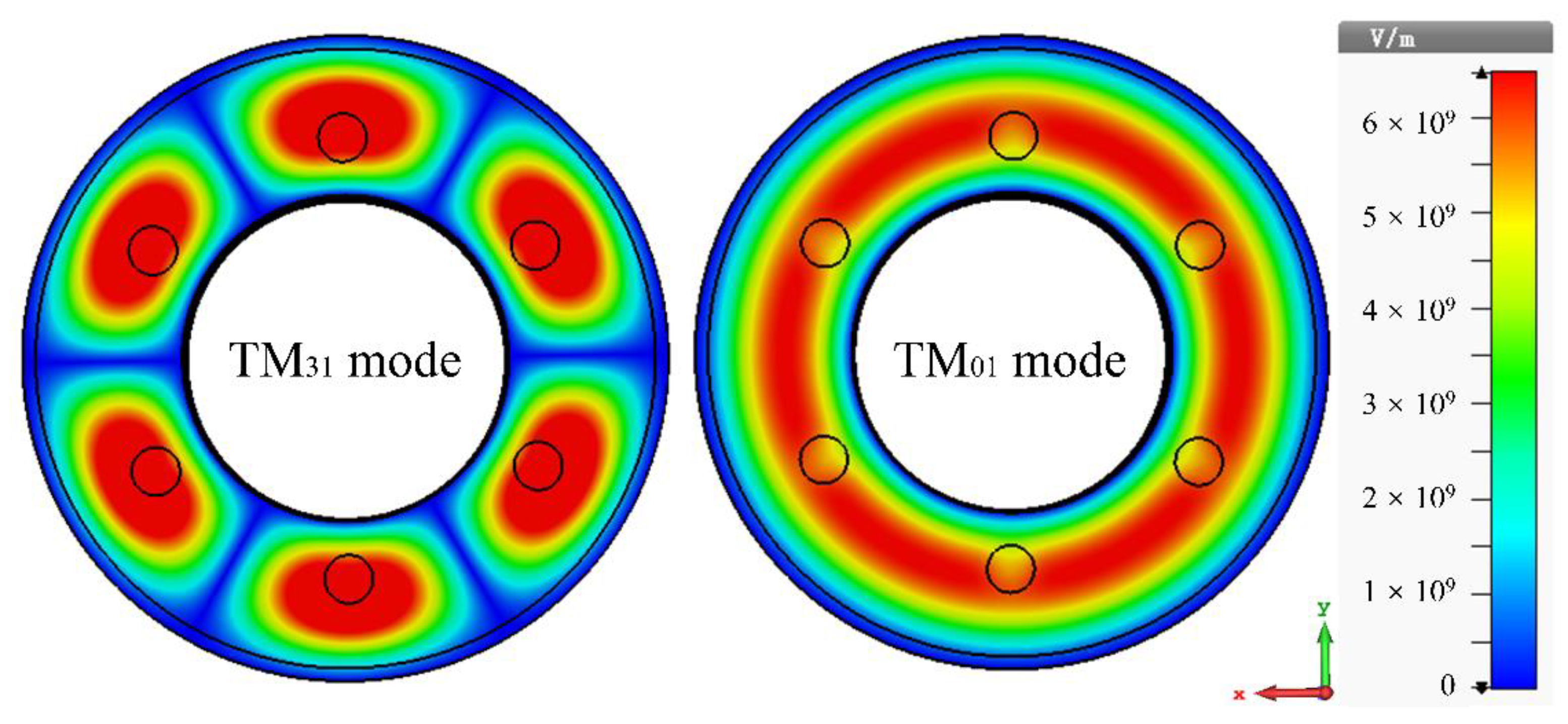
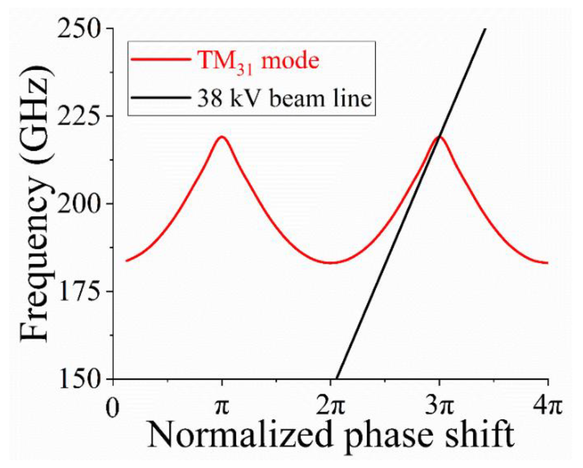
3. Preliminary Study of the TM31-3π Mode

In the same frequency range, the cavity volume of the TM01 mode EIO is smaller than the cavity volume of the TM31 mode EIO [18]. If a G-band EIO operates in the fundamental mode, its dimensions in the X and Y directions would be designed to be relatively small. However, the larger size EIO has more advantages at the same frequency. Firstly, the larger size means that the electron beam has a larger cross-sectional area, which greatly increases the input current at the same current density. At the same time, the large current greatly improves the output power. Secondly, it is easier to manufacture the bigger slow-wave structure at high frequency. Therefore, the G-band EIO operating in the TM31 mode is easier to fabricate than the G-band EIO operating in the TM01 mode.
Compared with the TM01 mode, the electric field distribution of the TM31 mode is more concentrated on the electron beam tunnels. The left part of Figure 3 shows the electric field distribution of the EIO’s TM31-3π mode in an X-Y cross section, from which it can be found that the higher electric field is distributed around the six electron beam tunnels. The right part of Figure 3 is the electric field distribution of the TM01-2π mode in an X-Y cross section. The higher electric field is mainly distributed on the ring covering the electron beam tunnels. The following CST Particle Studio simulations show that the EIO operates in TM31-3π mode when the electron beam voltage range is 38–43 kV, and that the main operating mode of the EIO changes to TM01-2π when the electron beam voltage exceeds 43 kV.
Figure 4 shows the dispersion curve of the multiple-beam EIO. The synchronous beam voltage of the TM31-3π mode is 38 kV. It can be seen from the dispersion curve that the 2π mode operating voltage of the multiple-beam EIO is greater than its 3π mode operating voltage. In other words, the 3π mode has a longer period length than the 2π mode under the same operating voltage, according to the EIO’s synchronous condition. Long period length is undoubtedly an advantage for the fabrication of slow-wave structures in the G-band and even the terahertz band. The comparison of period lengths and gap lengths of various G-band extended interaction devices are listed in Table 1. The other extended interaction devices in Table 1 all operate in 2π mode, and the period length and gap length of the multiple-beam EIO operating in 3π mode are relatively long. Operating in 3π mode significantly helps to increase the Z-direction dimension of an EIO.

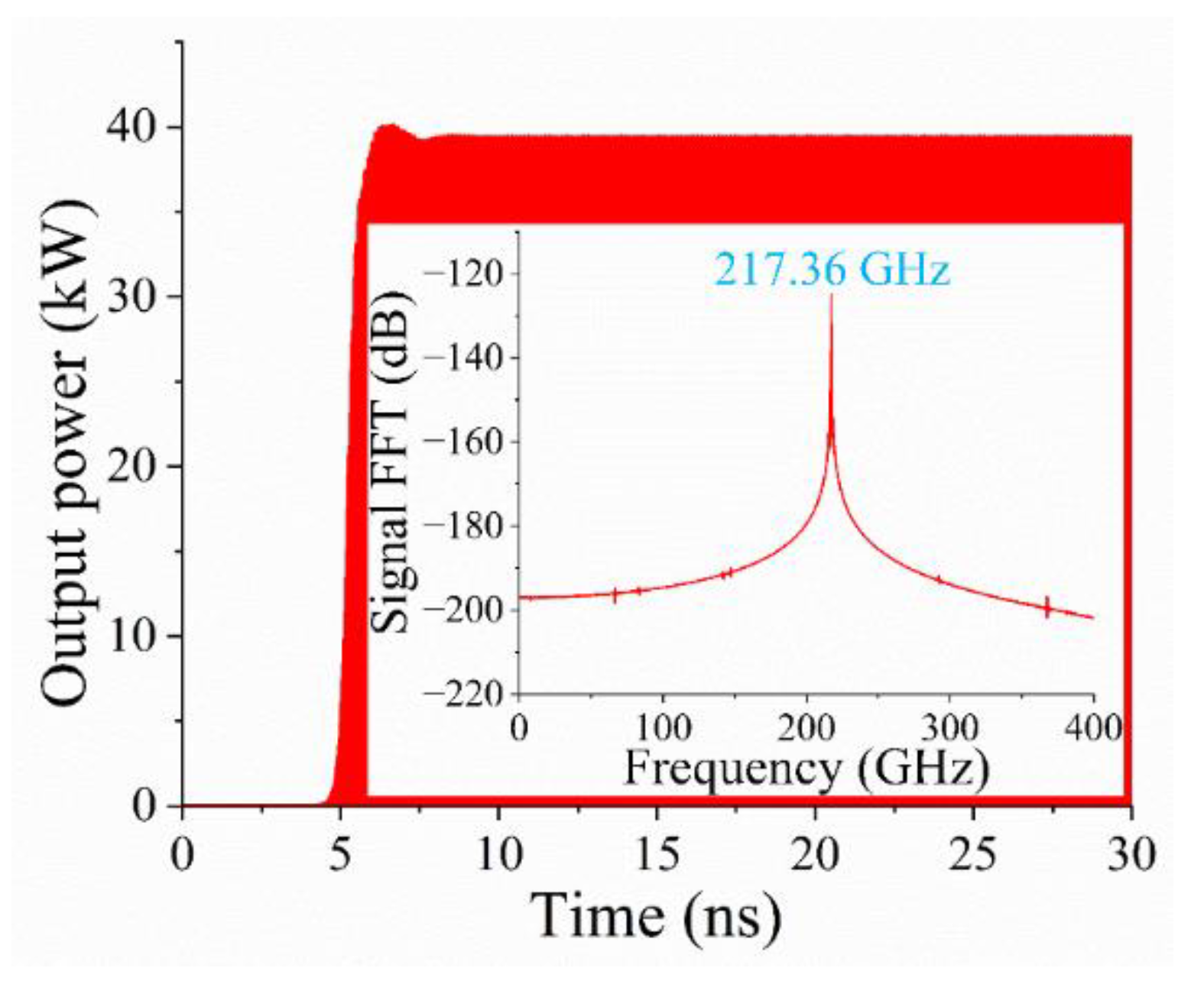
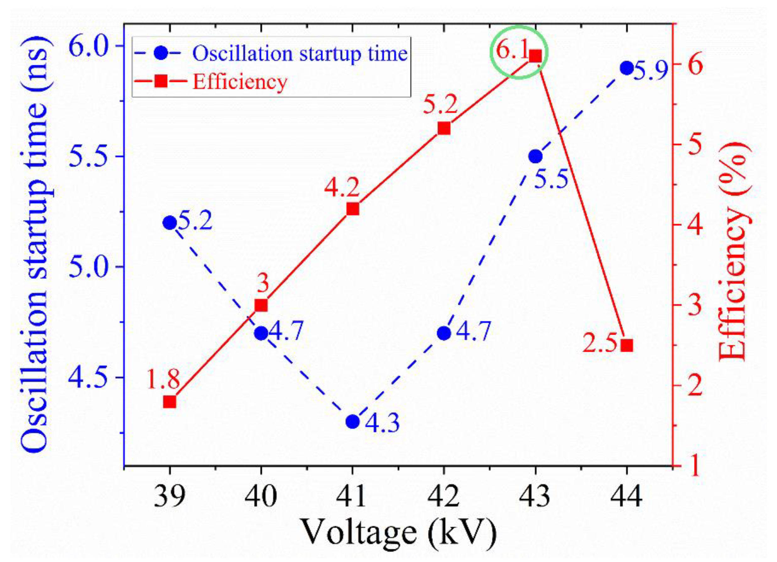
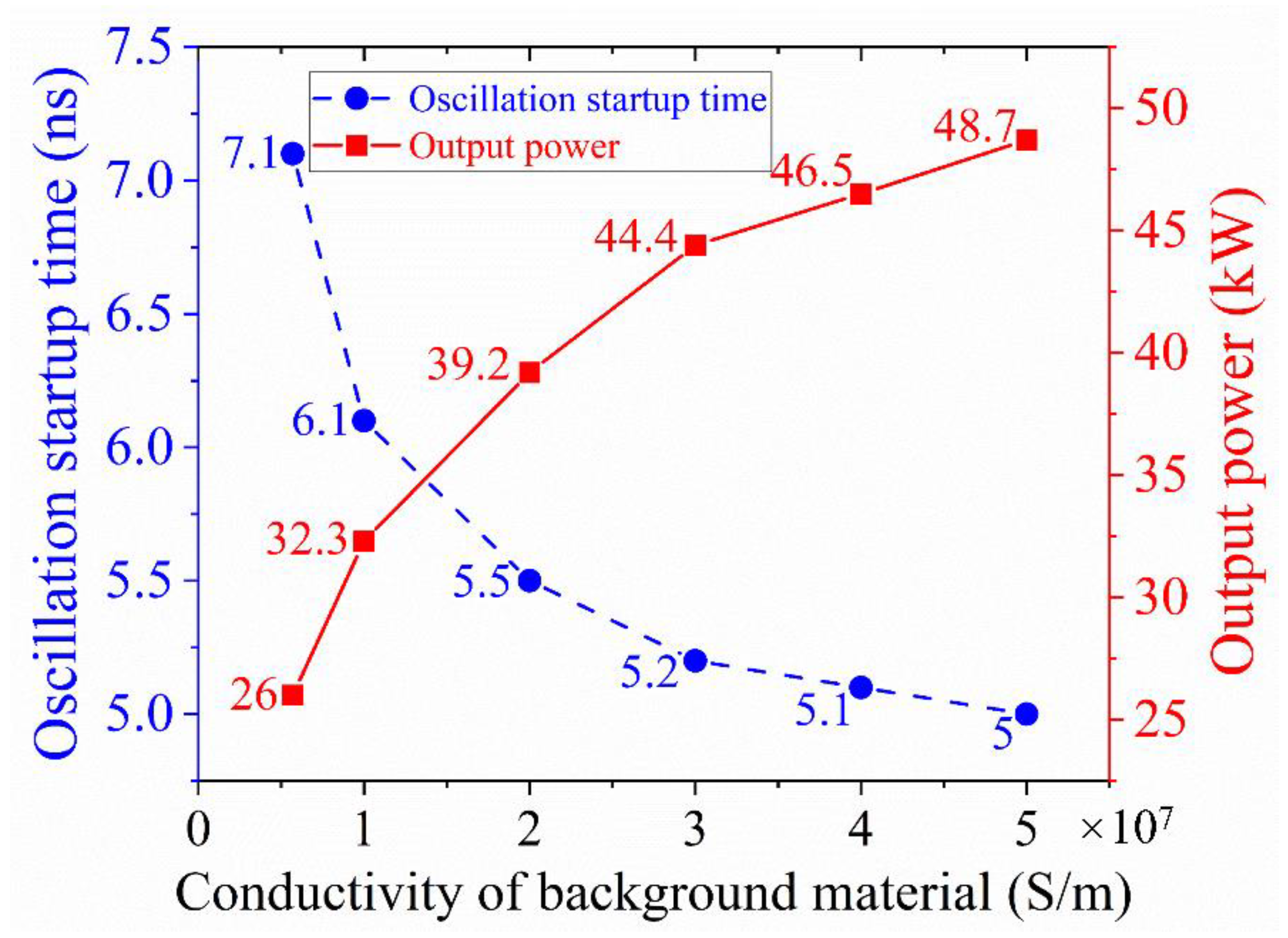
4. PIC Simulation of the PS Multiple Electron Beam EIO Operating in TM31-3π Mode

The authors used the CST Particle Studio to simulate the multiple-beam EIO. In the simulations, the input voltage is 43 kV and the input current is 15 A in total, which is evenly distributed among six electron beams. The magnitude of the axial magnetic field is 2.2 T, which is used to focus the electron beam. In Figure 5, a stable output signal of 39.2 kW, lasting 30 ns, has been realized at a frequency of 217.36 GHz. The oscillation startup time is very short, about 5.5 ns. The short oscillation startup time meets the requirement of fast oscillation of an EIO driven by PS electron beam. It can be seen from the frequency spectrum of the output signal that there is no mode competition in the multiple-beam EIO operating in the high-order mode.
The output power of 39.2 kW would exceed the power capacity of the single G-band standard waveguide. However, this paper is only a preliminary design and mainly discusses the improvement of the slow-wave structure by the combination of multiple PS electron beams and TM31-3π mode. In the follow-up designs, the authors will use multiple output ports to solve this problem. In the previous EIO experiments based on PS discharge [13], the output powers in the experiments were all much lower than the output powers in the simulations. Therefore, there is no need to worry about the power capacity of standard waveguide.
Figure 6a shows the 3D trajectory of the electrons in the multiple beam tunnels, from which the obvious electron bunching can be found. Periodic electron density modulation occurs as the electrons with higher energy keep up with electrons with lower energy. Simultaneously, part of the electrons’ power is converted into high frequency power. Figure 6b depicts the EIO’s electric field distribution at the Y-Z plane. The electric field distribution of the 3π mode in the slow-wave structure is similar to that of the π mode.
The trends of oscillation startup time and efficiency over electron beam voltage are plotted in Figure 7. The oscillation startup time with the voltage first decreases and then increases. The oscillation startup time data in Figure 7 are all extremely short, and they are far below the duration of pulse generated by the PS discharge. The efficiency peaks when the operating voltage reaches 43 kV and drops sharply when the operating voltage exceeds 43 kV. When the voltage range is 39–43 kV, the oscillation frequency is around 217 GHz and the operating mode is TM31-3π mode. When the voltage of the electron beams exceeds the optimal operating voltage, the output power and efficiency of the EIO drops sharply and the operating mode changes at the same time. In other words, when the voltage is 44 kV or even higher, the interaction circuit will operate at the non-3π mode.
Figure 8 shows the EIO’s oscillation startup time and its output power as influenced by the conductivity of background material. As the conductivity decreases, the output power decreases and the oscillation startup time increases. The surface ohmic loss is an unavoidable problem for EIOs, especially for devices operating at high frequency. When the surface roughness of the metal deteriorates, the loss increases sharply. As can be seen from the left-most data in Figure 8, when the conductivity of the background material is only σCu/10 (0.57 × 10⁷ S/m), the output power can still reach 26 kW.

5. Conclusions

This paper presents a preliminary design of a multiple PS electron beam EIO operating in the G-band. The device combines the advantages of multiple PS electron beams with the characteristics of TM31-3π mode. The PS electron source has extremely high current density and brightness and can self-focus without an external magnetic field. The merit of multiple electron beams is that the total electron beam cross-sectional area can be dramatically increased compared to only one electron beam. At the same frequency, the high-order mode can increase the cavity size of the interaction circuit compared to the fundamental mode, which further increases the cross-sectional area of the electron beam and increases the input current. Under the same operating voltage, the 3π mode has a longer period length than the traditional 2π mode, which means that the Z-direction dimension of the EIO operating in 3π mode is relatively large, such as the gap length. The advantages of 3π mode combined with the characteristics of high-order mode undoubtedly reduce the difficulty of fabrication.
The 3D PIC simulation results show the multiple PS electron beam EIO can steadily operate in the TM31-3π mode. The frequency spectrum shows that there is no mode competition. The beams’ voltage is 43 kV, and its current is 15 A in total, evenly distributed among six electron beams. The device has an output of 39.2 kW at 217 GHz, which corresponds to an efficiency of 6.1%, considering the conductivity of 2× 10⁷ S/m.

Author Contributions

Conceptualization, Y.Y. and L.B.; methodology, Y.Y. and H.L.; software, R.P. and X.X.; formal analysis, H.L.; investigation, R.P.; data curation, Y.Q.; writing—original draft preparation, R.P.; writing—review and editing, B.W.; visualization, X.Y.; supervision, Y.Y. and L.M.; project administration, L.M. All authors have read and agreed to the published version of the manuscript.

Funding

This research was funded by the National Natural Science Foundation of China (Grant Nos. 61671116, 61771096 and 11905026), the National Key Research and Development Program of China (Grant No. 2019YFA0210202) and the Fundamental Research Funds for the Central Universities (Grant Nos. ZYGX2019Z006 and ZYGX2019J012).

Data Availability Statement

Not applicable.

Conflicts of Interest

The authors declare no conflict of interest.

References

  1. Shu, G.; Liao, J.; He, J.; Ren, J.; Lin, J.; Lin, G.; Li, Q.; Ruan, C.; He, W. A Sub-THz High-Order Mode Backward Wave Oscillator Driven by Pseudospark Sourced Multiple Sheet Electron Beams. IEEE Trans. Electron Devices 2022, 69, 5216–5222. [Google Scholar] [CrossRef]
  2. Kumar, N.; Abhishek, A.; Vishant; Singhal, K.; Gurjar, N.; Jain, S.; Starodubov, A.V.; Ryskin, N.M. Pseudospark-Driven High-Current Miniaturized Voltage-Tunable Sheet-Electron-Beam Source. IEEE Trans. Electron Devices 2021, 68, 6482–6486. [Google Scholar] [CrossRef]
  3. Dubinov, A.E.; Saikov, S.K.; Tarakanov, V.P. Multivircator as a New Highly Effective Microwave Generator With Multiple Virtual Cathodes: Concept and PIC-Simulation. IEEE Trans. Plasma Sci. 2020, 48, 141–145. [Google Scholar] [CrossRef]
  4. Mumtaz, S.; Choi, E.H. An Efficient Vircator With High Output Power and Less Drifting Electron Loss by Forming Multivirtual Cathodes. IEEE Electron Device Lett. 2022, 43, 1756–1759. [Google Scholar] [CrossRef]
  5. Migliore, G.; Muratore, A.; Busacca, A.; Cusumano, P.; Stivala, S. Novel Configuration for a C-Band Axial Vircator With High Output Power. IEEE Trans. Electron Devices 2022, 69, 4579–4585. [Google Scholar] [CrossRef]
  6. Mumtaz, S.; Uhm, H.; Lim, J.S.; Choi, E.H. Output-Power Enhancement of Vircator Based on Second Virtual Cathode Formed by Wall Charge on a Dielectric Reflector. IEEE Trans. Electron Devices 2022, 69, 2043–2050. [Google Scholar] [CrossRef]
  7. Booske, J.H.; Dobbs, R.J.; Joye, C.D.; Kory, C.L.; Neil, G.R.; Park, G.S.; Park, J.; Temkin, R.J. Vacuum Electronic High Power Terahertz Sources. IEEE Trans. Terahertz Sci. Technol. 2011, 1, 54–75. [Google Scholar] [CrossRef]
  8. Shu, G.; He, W.; Zhang, L.; Yin, H.; Zhao, J.; Cross, A.W.; Phelps, A.D.R. Study of a 0.2-THz Extended Interaction Oscillator Driven by a Pseudospark-Sourced Sheet Electron Beam. IEEE Trans. Electron Devices 2016, 63, 4955–4960. [Google Scholar] [CrossRef] [Green Version]
  9. Pasour, J.; Wright, E.; Nguyen, K.T.; Balkcum, A.; Wood, F.N.; Myers, R.E.; Levush, B. Demonstration of a Multikilowatt, Solenoidally Focused Sheet Beam Amplifier at 94 GHz. IEEE Trans. Electron Devices 2014, 61, 1630–1636. [Google Scholar] [CrossRef]
  10. Varun; Sharma, N.K.; Pal, U.N. Design of Multigap Pseudospark Discharge-Based Plasma Cathode Electron Source at Different Configurations of Electrode Apertures. IEEE Trans. Electron Devices 2021, 68, 5799–5806. [Google Scholar] [CrossRef]
  11. Yin, H.; He, W.; Cross, A.W.; Phelps, A.D.R.; Ronald, K. Single-gap pseudospark discharge experiments. J. Appl. Phys. 2001, 90, 3212–3218. [Google Scholar] [CrossRef]
  12. Yin, H.; Cross, A.W.; Phelps, A.D.R.; Zhu, D.; He, W.; Ronald, K. Propagation and post-acceleration of a pseudospark-sourced electron beam. J. Appl. Phys. 2002, 91, 5419–5422. [Google Scholar] [CrossRef]
  13. Zhang, L.; Yin, H.; He, W.; Chen, X.; Zhang, J.; Cross, A. Pseudospark-sourced beam and its application in high-power millimeter-wave generation. Sci. Rep. 2021, 11, 19076. [Google Scholar] [CrossRef] [PubMed]
  14. Tom, S.; Jonathan, P.; David, F.; Helen, Y.; Adrian, C.; Wenlong, H.; David, B.; Kevin, R.; Alan, P. A MEMS fabrication approach for a 200GHz microklystron driven by a small-scaled pseudospark electron beam. Proc. SPIE 2010, 7837, 783705. [Google Scholar]
  15. Yin, H.; Robb, G.R.M.; He, W.; Phelps, A.D.R.; Cross, A.W.; Ronald, K. Pseudospark-based electron beam and Cherenkov maser experiments. Phys. Plasmas 2000, 7, 5195–5205. [Google Scholar] [CrossRef] [Green Version]
  16. Pal, U.N. PIC Simulation to Analyze Peak Electron Current Generation in a Triggered Pseudospark Discharge-Based Plasma Cathode Electron Source. IEEE Trans. Electron Devices 2018, 65, 1542–1549. [Google Scholar] [CrossRef]
  17. Zhang, R.; Wang, Y. Six-Beam Gun Design for a High Power Multiple-Beam Klystron. IEEE Trans. Electron Devices 2013, 60, 2395–2401. [Google Scholar] [CrossRef]
  18. Zhang, X.; Zhang, R.; Wang, Y. Research on a High-Order Mode Multibeam Extended-Interaction Oscillator With Coaxial Structure. IEEE Trans. Plasma Sci. 2020, 48, 1902–1909. [Google Scholar] [CrossRef]
  19. Peng, R.; Li, H.; Yin, Y.; Xu, X.; Chen, Q.; Bi, L.; Xu, C.; Wang, B.; Yuan, X.; Zhang, P.; et al. Research of the Oscillation Start-Up Time in an Extended Interaction Oscillator Driven by a Pseudospark-Sourced Sheet Electron Beam. Electronics 2022, 11, 664. [Google Scholar] [CrossRef]
  20. Xu, C.; Meng, L.; Hu, C.; Yin, Y.; Zhu, S.; Chang, Z.; Bi, L.; Peng, R.; Wang, B.; Li, H.; et al. Analysis of Dual-Frequency Radiation From a ${G}$ -Band Extended Interaction Oscillator With Double Sheet Beam. IEEE Trans. Electron Devices 2019, 66, 3184–3189. [Google Scholar] [CrossRef]
  21. Zhang, F.; Zhao, Y.; Ruan, C. A High-Power and Broadband G-Band Extended Interaction Klystron Based on Mode Overlap. IEEE Trans. Electron Devices 2022, 69, 4611–4616. [Google Scholar] [CrossRef]
Figure 1. The schematic drawing of the five-gap PS electron beam discharge setup and multiple-beam EIO.
Electronics 11 03961 g001
Figure 2. The schematic drawings of the multiple-beam EIO with coaxial structure and its sectional view on the X-Y plane.
Electronics 11 03961 g002
Figure 3. The difference between the electric distribution of TM31 mode and the electric distribution of TM01 mode in an X-Y cross section.
Electronics 11 03961 g003
Figure 4. The dispersion curve of the coaxial multiple-beam EIO and 38 kV beam line.
Electronics 11 03961 g004
Figure 5. Time-dependent output power and frequency spectrum of CST Particle Studio simulation results.
Electronics 11 03961 g005
Figure 6. (a) A snapshot of 3D trajectory of the electrons in the six beam tunnels and (b) the EIO’s electric field distribution at the Y-Z plane after oscillation.
Electronics 11 03961 g006
Figure 7. The EIO’s oscillation startup time and efficiency versus electron beam voltage.
Electronics 11 03961 g007
Figure 8. The EIO’s oscillation startup time and output power versus the conductivity of background material.
Electronics 11 03961 g008
Table 1. Period lengths and gap lengths of various G-band extended interaction devices.
Extended Interaction DevicesPeriod LengthGap Length
A sheet beam G-band EIO [19]0.56 mm0.18 mm
A double sheet beam G-band EIO [20]0.4 mm0.12 mm
A G-band EIK [21]0.16 mm0.08 mm
The multiple-beam G-band EIO mentioned in this paper0.75 mm0.29 mm
Publisher’s Note: MDPI stays neutral with regard to jurisdictional claims in published maps and institutional affiliations.

