Article

Research on Retinex Algorithm Combining with Attention Mechanism for Image Enhancement

The Higher Educational Key Laboratory for Measuring & Control Technology and Instrumentation of Heilongjiang Province, Harbin University of Science and Technology, Harbin 150080, China
*
Author to whom correspondence should be addressed.
Electronics 2022, 11(22), 3695; https://doi.org/10.3390/electronics11223695
Submission received: 9 October 2022 / Revised: 5 November 2022 / Accepted: 9 November 2022 / Published: 11 November 2022
(This article belongs to the Special Issue Deep Learning in Image Processing and Pattern Recognition)

Abstract

:
Considering the high noise and chromatic aberration in the Retinex-Net image enhancement results, this paper put forward a modified Retinex-Net algorithm for weak illumination image enhancement based on the Decom-Net and Enhance-Net structures of Retinex-Net. The improved structure proposed in this paper adds the attention mechanism ECA-Net into the Decom-Net and Enhance-Net convolution layer of the original Retinex-Net structure, which can effectively reduce the problem of irrelevant background and local brightness imbalance, activate sensitive features, and improve the image’s details and brightness processing ability. Additionally, deep connected attention networks are embedded between the introduced attention modules, so that all of the attention modules can be trained jointly to improve the learning ability. Furthermore, the improved method also introduces a noise reduction loss function and a color loss function to suppress noise and to reduce image color distortion. The test results of the proposed method indicate that the image’s overall brightness can be balanced, the local areas cannot be overexposed, and more image details and color information can be retained than with other enhancement algorithms.

1. Introduction

Weak illumination image enhancement technology has recently become an important research topic. When the shooting environment is dark, the image’s brightness and contrast will be affected, and the color will be distorted, which will affect intuitive visual effects and subsequent detections of image enhancement [1,2,3]. To enhance the low-light image, in that early stage, people performed a lot of research on histogram equalization [4,5]. The method in literature [6] is inspired by the dark channel prior defogging theory [7], and it is found that the visual effect and histogram of low illumination images after inversion are highly similar to those of fogged images. Based on this observation, literature [6] applied the defogging algorithm to the inverted weak illumination image and flipped it again to obtain the enhanced weak illumination image. Land put forward the theory of the retina cortex [8,9,10] (Retinal Cortex Theory, Retinex). With the development of research, machine learning methods can be applied. The combination of Retinex theory and CNNs further improves the effect of image enhancement [11,12,13]. However, after the Decom-Net extracts the reflection parts, the noise level will be affected by the light intensity, which makes the dark area’s noise too high, causing the noise and color deviation of the low illumination enhanced result of Retinex-Net. Therefore, this paper put forward a modified algorithm based on Retinex-Net to ameliorate the effect of the enhanced image.

2. Retinex Image Enhancement Algorithm

At first, the gray value of the low illumination image’s dark area is changed by histogram equalization and gamma correction to increase the image brightness [14]. However, these methods only consider the image’s global information, ignoring the details. The Retinex theory is based on color consistency, which can decompose the color image into a reflection part and an illumination part. As shown in Formula (1):
S = R I
where denotes a pixel-by-pixel multiplication operation. S denotes a color image, in which the illumination of each region is different. R denotes a reflection part, which is an inherent physical property of an object, and the true color of the object is independent of the luminance. I denotes the illumination part, which reflects the degree of exposure of the photographic object.

2.1. Surround Retinex Method

The single-scale Retinex (SSR) uses the convolution of the surround function and the input image to obtain the illumination part. The SSR algorithm expression is presented in Formula (2):
R i ( x , y ) = lg I i ( x , y ) L i ( x , y ) = lg I i ( x , y ) lg [ F ( x , y ) I i ( x , y ) ]
F ( x , y ) = 1 2 π σ 2 e ( x 2 + y 2 ) σ 2
where i denotes different RGB channels, I i ( x , y ) denotes the input image, and L i ( x , y ) denotes the incident part, defined by the convolution yields of F ( x , y ) and I i ( x , y ) . R i ( x , y ) denotes the reflection part. F ( x , y ) denotes the wrap function, as shown in Equation (3), where σ is the scale parameter; the size of σ determines the effect of image enhancement [15].
The multiscale Retinex (MSR) is a weighted sum of SSR outputs at multiple scales [16]. The MSR algorithm expression is presented in Formula (4):
R M S R i ( x , y ) = 1 N ω n R n i ( x , y )
where ω n is the weighted value, and N is the number of scales. R n i ( x , y ) denotes the reflection image at the n-th scale. The surrounding function expression of R n i ( x , y ) is shown in Formula (5):
F n ( x , y ) = 1 2 π σ 2 e ( x 2 + y 2 ) σ 2
The MSRCR algorithm adds a color restoration factor C i used to improve the color deviation problem caused by the MSR algorithm [17], and the MSRCR expression is shown in Formula (6):
R M S R C R i ( x , y ) = C i ( x , y ) R M S R i ( x , y )
where C i ( x , y ) denotes the color recovery factor of the i-th channel in R, G, and B, and its expression is shown in Equation (7):
C i ( x , y ) = β ln [ α I i ( x , y ) i = 1 S I i ( x , y ) ]
where β denotes the gain coefficient and α denotes the nonlinear controlled intensity factor. According to [18], β = 46 and α = 125 . S presents the spectral channels, S = 1 presents a grayscale image, and S = 3 presents an RGB color image.

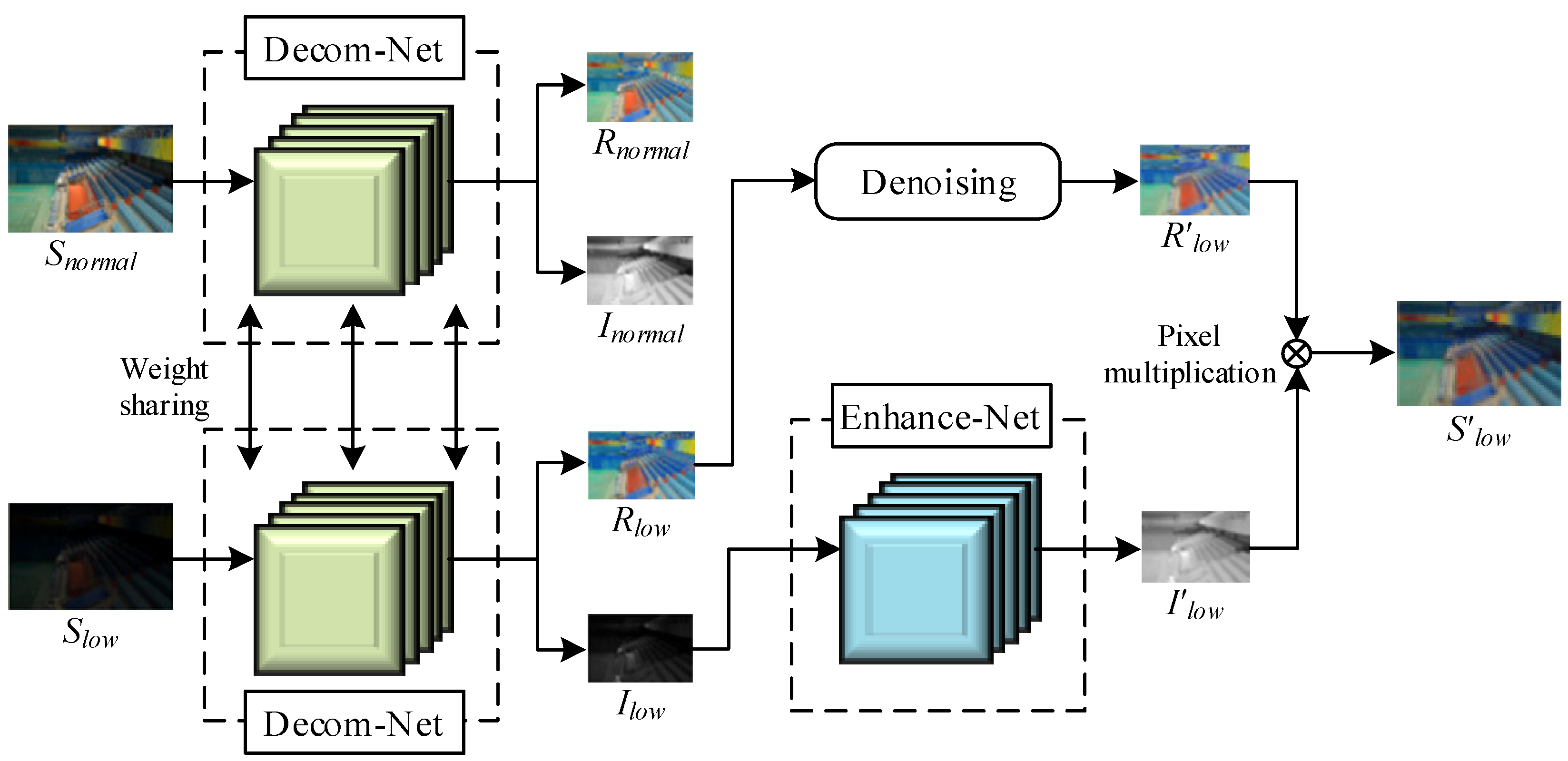
2.2. The Retinex-Net Model

Most of the existing image enhancement methods based on Retinex rely on the careful design of constraints and parameters by hand. Therefore, when these methods are applied in different scenarios, they may be trapped by the model’s capacity. Retinex-Net can automatically learn the input weak illumination image’s features, which solves the problem that the traditional algorithm relies on manually setting parameters. The Retinex-Net model structure is presented in Figure 1. It consists of three parts: the decomposition model, adjustment model, and reconstruction. Namely, Decom-Net and Enhance-Net form the primary network of the Retinex-Net.
The Decom-Net uses a 3 × 3 convolution layer to generate the characteristic of the input image, and uses the linear rectification function ReLU as the activation function. After five 3 × 3 convolution layers with ReLU, the RGB image is divided into reflection and illumination images. The low-light image S l o w and the matched normal-light image S n o r m a l are respectively input into the Decom-Net model, and the network parameters are shared by the two images, decomposed into the corresponding reflection parts ( R l o w , R n o r m a l ) and illumination parts ( I l o w , I n o r m a l ). Comparing the output images of the decomposition model in Figure 1 shows that the reflection parts R l o w and R n o r m a l under normal illumination and low illumination are relatively similar. In contrast, the large difference in the illumination part between I l o w and I n o r m a l indicates that the reflection part is the inherent attribute of the image, which is not easily affected by the original shooting illumination intensity. The illumination part determines the visual perception of the human eye when observing the image.
In the denoising process of the reflection image, the three-dimensional block matching algorithm (BM3D) [19] is mainly used to reduce the noise of the reflection part to obtain a denoised reflection image, R l o w . The main idea of the BM3D is to find a reference block with a step of s in the image, search in the vicinity of the reference block, and find some blocks with small differences from the reference block. Then, these blocks will be integrated into a three-dimensional matrix for filtering, and finally, the results are fused into a two-dimensional image using inverse transformation to obtain a denoised image.
The Enhance-Net adopts the encoder–decoder structure and inputs the illumination part I l o w obtained by Decom-Net. The feature map with a smaller size is obtained through multiple down-sampling layers so that the light intensity is redistributed with larger scale angles in the Enhance-Net, and it can adjust the brightness. The Enhance-Net reconstructs the light intensity of the image through up-sampling, allocates lower brightness to a locally brighter place, and allocates higher brightness to a locally darker place. Furthermore, the output of the up-sampling layer is cascaded by the number of channels so that different local illuminations are adjusted, and the global illuminations of the image are kept consistent. At the same time, the element-by-element summation is used to guide skip connections from one down-sampling layer to its corresponding mirrored up-sampling layer so that the network learns the residual. The low illumination part I l o w is subjected to the Enhance-Net to generate an enhanced illumination part, I l o w . Finally, the enhanced illumination part I l o w is recombined by multiplying the two images’ pixels and the denoised reflection part R l o w , forming the enhanced image S l o w as the network output.

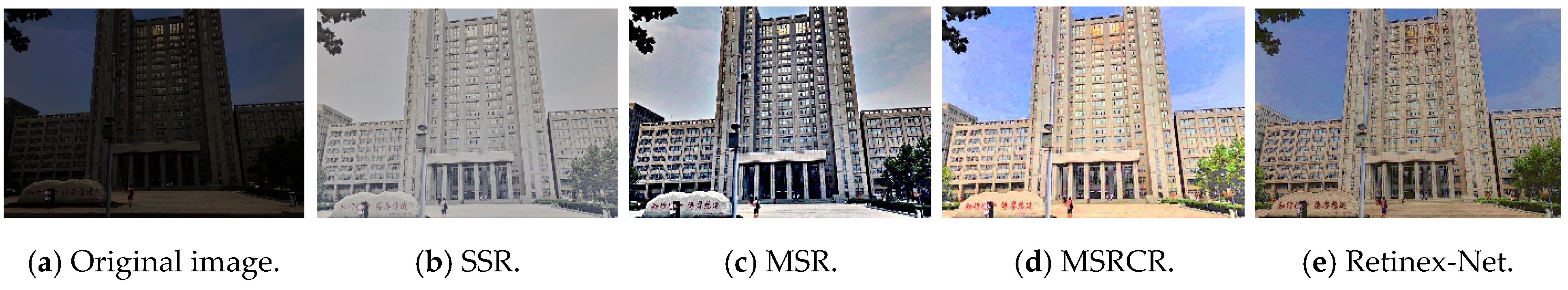
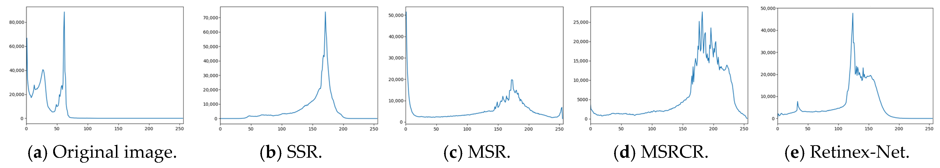
2.3. Image Enhancement Test and Analysis

In this paper, the images under low illumination are selected, and the enhancement effects of the SSR, MSR, MSRCR, and Retinex-Net algorithms are evaluated. Figure 2a is a dark image to be processed with low brightness and contrast. Figure 2b–e are effect pictures based on four enhancement algorithms of SSR, MSR, MSRCR, and Retinex-Net. Figure 3a–e are gray histograms of the images.
From the gray histograms of Figure 3a–e, it is found that the basic structure of the enhanced image is quite different from the original image, indicating that the image’s brightness is significantly improved. Combined with the enhancement effect and the gray histogram, it is shown that SSR only retains the low-frequency part, which improves the overall brightness while losing the important high-frequency part of the input image. MSR is less sensitive to the highlighted area and loses the image’s color characteristics. Although MSRCR recovers the color, the color retention ability is not good enough, and the image is overexposed. Although Retinex-Net has the fastest processing speed and can obtain a better enhancement effect without manually setting parameters, it has the phenomena of large noise and color distortion. Therefore, this paper introduces the attention mechanism and adds the denoising loss and the color loss to ameliorate the traditional Retinex-Net, aiming at the shortcomings of Retinex Net’s inability to retain image texture details and color features.

3. The Improved Retinex-Net Model

In the convolution process, each channel in the default feature map has the same importance, while facing the actual problem, and the importances of different channels are different. The attention mechanism can reallocate the input weight during convolution. The introduction of the attention mechanism in Retinex-Net can reduce the attention of the network to the irrelevant features of the image and only focus on the crucial parts of the image, such as color, texture, and shape, to improve the processing ability of image brightness and details.

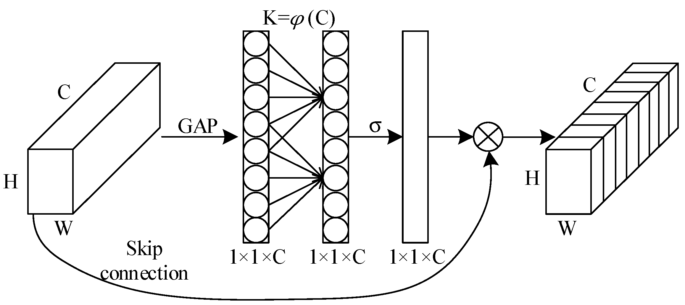
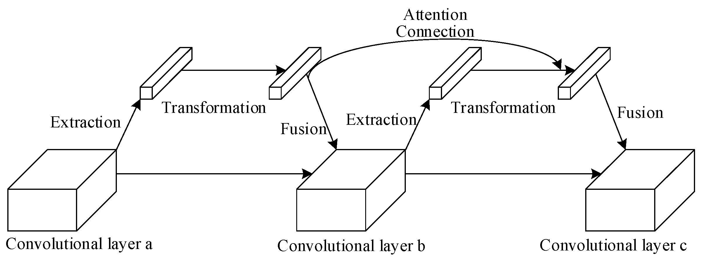
3.1. Introduction of Attention Mechanism and Its Deep Connection

ECA-Net (Efficient Channel Attention Network) is an efficient channel attention mechanism [20], which avoids feature dimension reduction in the previous attention mechanism and enables the information between channels to interact effectively. After channel-level global average pooling (GAP) without dimension reduction, it uses the one-dimensional sparse convolution operation to capture the current channel and its k domain channel information. The interaction of domain channel information dramatically reduces the number of parameters and improves the performance. The ECA module structure is shown in Figure 4 below. Embedding the ECA module in the Decom-Net can learn the importance of each feature channel adaptively. Each noise point is normalized and weighted during the denoising process, which automatically removes noise points, improves the clarity of decomposed image, and reduces the loss of key features.
Assume that input from the previous convolution layer is a H × W × C feature map of C channels in total, and then map each two-dimensional feature channel to a real Z using Formula (8) through global average pooling. Output a 1 × 1 × C global description feature, and the mapping relationship is shown in Formula (8):
Z = 1 H × W i = 1 H j = 1 W X C ( i , j )
where X C ( i , j ) denotes the C-th two-dimensional matrix in the input feature map, which indicates the numerical distribution of the C feature maps in this layer, and Z denotes the obtained global information. Then, a one-dimensional convolution with a convolution kernel size of k captures the local cross-channel interaction information, obtains the normalized weights through the Sigmoid activation function, and acts on the previous feature map. To make the model more lightweight and compact, the ECA model simplifies the dense connection mode in the SE module of the previous attention mechanism, avoids complex channel dependence or combines additional spatial attention, and only considers the information interaction in adjacent channels. The weight calculation formula is as shown in Formula (9):
ω i = σ ( j = 1 k ω i j y i j ) , y i j Ω i k
where σ denotes the Sigmoid function and y i denotes the channel. ω i is the weight of the channel y i , ω i k is the set of the k -th neighboring channel of y i , and k is the convolution kernel size, which denotes the coverage of local cross-channel interaction, which signifies how many adjacent channels close to the channel participate in the attention prediction of the channel. Meanwhile, to avoid manually tuning the value of k , the ECA module will adaptively determine k . One-dimensional convolution with the kernel size of k can realize the effective channel attention module, as shown in Formula (10):
ω = σ ( C 1 D k ( y ) )
where C 1 D k denotes the one-dimensional convolution operation with convolution kernel k , and y denotes the channel. The coverage of cross-channel information interactions (i.e., the kernel size k of the one-dimensional convolution) is proportional to the channel dimension C . There is a mapping relationship φ between k and C . Because the linear mapping relationship has limitations for some related features, the mapping relationship φ adopts a nonlinear mapping. Taking into account that the channel dimension is typically an exponential multiple of 2, the linear map relation is introduced into the nonlinear mapping relation. The expression of the mapping relationship with the channel dimension C and the convolution kernel size k is shown in Equation (11), where η and b are constants representing the linear mapping relationship, and η = 2, b = 1 is taken [18].
k = φ ( C ) = | log 2 ( C ) η + b η | o d d
Although the attention mechanism can play a good role in many image processing tasks, it is limited to the current features each time, and does not fully use the attention mechanism. DCA-Net (Deep Connected Attention Network) can establish skip connections between adjacent ECA attention modules so that information interacts between each attention module, and all attention modules are jointly trained [21]. This improves the ability of the attention mechanism to learn important features of images, and optimizes the performance of Retinex-Net to extract features of reflection images and restore illumination images and colors. The DCA module is plug-and-play, improving attention performance without changing the internal structure of the Retinex-Net model.
The DCA uses a general attention framework consisting of three parts: Context Extraction, Transform, and Fusion, and the network structure is shown in Figure 5. Firstly, the ECA module extracts the feature G from the input feature map X through the extractor g with a global average pooling, where X R H × W × C , and ω g is the relevant parameter of the extraction operation. The extractor g determines the relevant parameter. When g is a no-parameter operation, such as a pooling operation, ω g is no longer needed. Then, the extracted feature blocks are transformed into a new nonlinear attention space T by using a one-dimensional convolution kernel and an excitation function, and the output T can be indicated as T = t ( G , ω t ) . t is defined as the feature transformation operation, and ω t is the parameter used in the transformation operation. Finally, the attention map is fused with the original convolution block feature and the output is X = T X . denotes the feature fusion mode, and the fusion function performs element multiplication when it is designed to be scaled, and performs element addition otherwise. To sum up, the model of a general attention module can be expressed as Equation (12):
X = t ( g ( X , ω g ) , ω t ) X
The DCA module will introduce a connection channel between each attention block to fuse the feature output extracted by the previous attention module with the output of the current attention module. This design ensures that the present attention module can learn the extracted features and the former information. From this, the attention module can be indicated as Formula (13):
X = t ( f ( α G , β T ) , ω t ) X
where f is a link function, a and β are learnable parameters, and T ˜ denotes the attention mapping feature map generated by the former attention module. Since the improvement of network performance is more from the connection among attention blocks [19] rather than the form of the connection function, it is not sensitive to the connection mode. Therefore, the connection mode between attention blocks uses direct connection by default, and the connection function f is as shown in Formula (14):
f ( α G , β T ˜ ) = α G + β T ˜

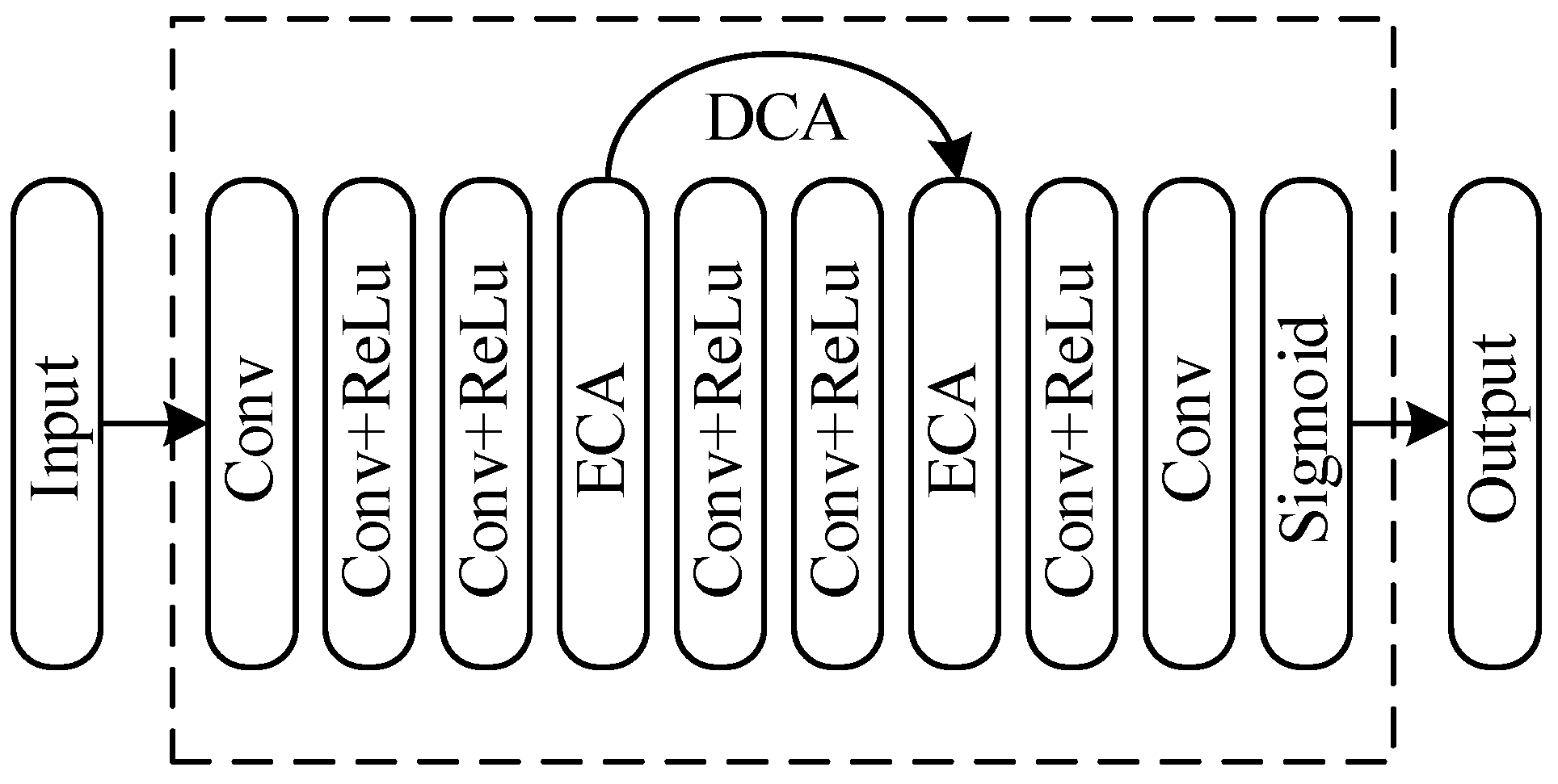
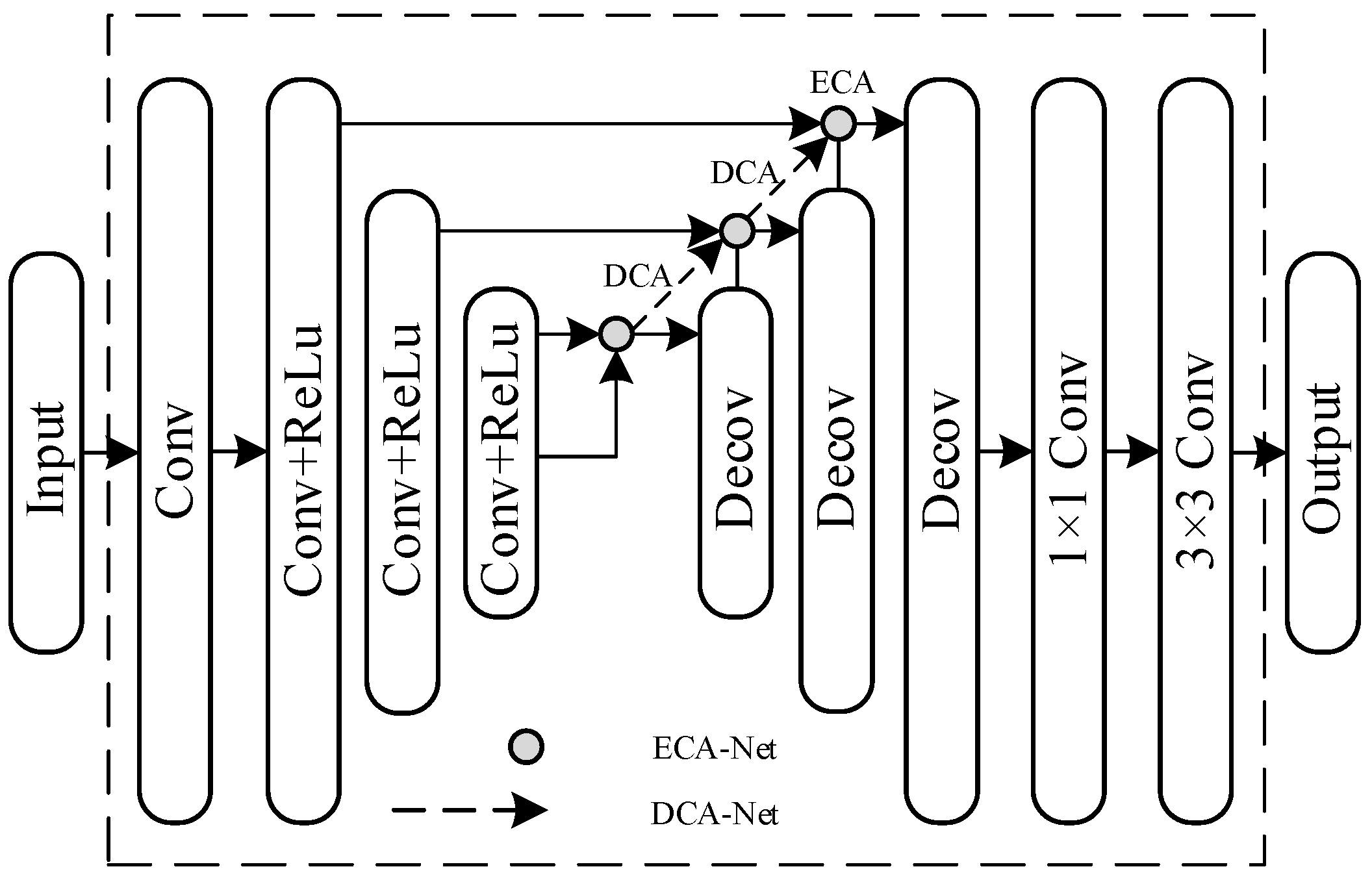
3.2. Improvement of Subnetworks

Aiming at the problem that the original Decom-Net is not conducive to preserving image details and suppressing noise, this paper first improves and optimizes the structure of the Decom-Net in the original Retinex-Net model. The improved Decom-Net model is shown in Figure 6. First, the Decom-Net uses a 3 × 3 convolution layer to extract the input image S l o w . Then, it uses five convolution layers with ReLU activation functions to change the size of the feature map and to learn the characteristic of the reflection part R l o w and the illumination part I l o w . The attention mechanism ECANet is added after the convolutions of the second and fourth layers, respectively, and the deep connection attention DCA is established between the two attention blocks. Finally, using the convolution layer and Sigmoid function, the learned image features are mapped into a reflection image R l o w and an illumination image I l o w , and then output.
The original Retinex-Net has the problem of image color distortion. This paper ameliorates the structure of the Enhance-Net based on the original Retinex-Net to improve the color distortion. Firstly, the Enhance-Net uses a 3 × 3 convolution layer to extract the features of the low-light input obtained by Decom-Net. Then, the encoder–decoder architecture obtains the context information in a large area, and the local illumination distribution is reconstructed. The skip layer is connected between the down-sampling layer and the corresponding mirror-image up-sampling layer. The attention module ECA is added to the connection between the upper sampling layer and the jump layer to reduce the response of the network to image-independent features, so that the next upper sampling layer can carry more illumination information. Additionally, deep connections are established between the attention modules to strengthen the attention mechanism’s attention to the image’s brightness, and further improve the network’s learning ability of brightness characteristics. Finally, these feature maps are adjusted to the final scale at different scales using the nearest neighbor interpolation algorithm. By using a 1 × 1 convolution layer and a 3 × 3 convolution layer to reduce the number of channels, the illumination image is reconstructed. The improved augmented network model is shown in Figure 7:

3.3. Improvement of Loss Functions

As for the loss function of the Decom-Net, the proposed method retains the reconstruction loss r e c o n , invariable reflectance loss i r , and illumination smoothness loss i s of the original Decom-Net. In addition, a denoising loss d n is added for further denoising. Thus the total loss d e is shown in Formula (15):
d e = r e c o n + λ i r i r + λ i s i s + λ d n d n
where λ i r , λ i s , and λ d n are the coefficients of each type of loss used to balance each loss part.
Based on the output result R l o w and R n o r m a l in the Decom-Net, and under the assumption that the images can be reconstructed using the respective illumination maps I l o w and I n o r m a l , the reconstruction loss is described by Equation (16):
r e c o n = i = l o w , n o r m a l j = l o w , n o r m a l λ i j R i I j S j 1
where denotes the pixel multiplication. According to reference [10], when i takes low or j takes normal, the weight coefficient λ i j = 1 , otherwise, λ i j = 0.001 . The Decom-Net uses larger weight coefficients to better learn the paired images’ characteristics with low and normal illumination.
The invariable reflectance loss constrains the network from learning the reflectivity of the low-illumination and normal-illumination images. According to the color consistency of Retinex theory, the color reflected by the object is irrelevant to the light intensity and has consistency, as shown in Formula (17):
i r = R l o w R n o r m a l 1
A good light map should be smooth in detail while preserving the overall structural boundaries. Illumination smoothness loss avoids the problem that the image detail and the boundary gradient are uniformly reduced when the total variation (TV) is directly used as the loss function so that the illumination is blurred and black edges exist on the reflection map. Weighting the original TV function and the reflectance gradient, R i makes the brightness of the illumination map smoother, and image characteristics are favorably retained. The final i s is shown in Formula (18):
i s = i = l o w , n o r m a l   I i exp ( λ g R i ) 1
where λ g presents the balance coefficient of the strength of structure awareness. Then, exp ( λ g R i ) relaxes the smooth constraint at the steeper reflection gradient, where the image structure is more complex, and the lighting is discontinuous.
When SSIM is used as the loss function, although it can better constrain the structural features of the network learning image, it is less sensitive to the smooth region of the image, and it needs a specific configuration to perform well. Although MSSSIM with multiscale structure similarity can keep high-frequency information well for images with different resolutions, it is easy to change the brightness and produce color deviation. In comparison, the L1 loss function can maintain brightness and color more effectively. Hence, for that, the denoising loss d n is optimized using a hybrid loss function of MSSSIM and L1 loss, where the expression of MSSSIM is as shown in Equation (19); then the expression is shown in Formula (20):
M S S S I M ( P ) = 1 M S SSIM ( p ˜ )
d n = α M S S S I M + ( 1 α ) G σ G M L 1
where p ˜ is the center point pixel, α is the coefficient, L 1 is the L1 loss function, and α is taken as 0.84 according to [22]. G σ G M is the Gaussian distribution coefficient of the pixel point, and the approximate value is used instead of the pyramid structure to reduce the calculation cost [22].
When denoising loss, d n is L1, SSIM, MSSSIM, and MSSSIM are mixed with L1, and the denoising evaluation results from the literature [22] are shown in Table 1, where the mixing loss is recorded as Mix.
As for the loss function of the Enhance-Net, the proposed method retains the reconstruction loss and illumination smoothness loss of the original Enhance-Net. In addition, color loss c o l o r is also added to enhance the saturation of the color and to improve the color deviation problem. Therefore, the total loss constraint e n of the network is shown in Equation (21), where μ is the balance coefficient of color loss function c o l o r .
e n = r e c o n + i s + μ c o l o r
The reconstruction loss of Enhance-Net is defined as the distance between the normal image and the corresponding enhanced illumination image, as shown in Equation (22):
r e c o n = R l o w I S n o r m a l 1
The illumination smoothness loss resembles that of the Decom-Net. The only difference is that I l o w in the Enhance-Net takes the gradient of R l o w as the weight coefficient, and its expression is shown in Equation (23):
i s = I l o w exp ( λ g R l o w ) 1
The color loss function c o l o r uses the Huber loss function to enhance the saturation of the color; i.e., c o l o r = h . The Huber loss is a robust estimator, and has been shown to solve the average coloring [23,24], so it helps to increase the color saturation of images in Enhance-Net. The expression of the Huber loss function is shown in Equation (24):
h = { 1 2 ( I r I ˜ ) 2 I r I ˜ < δ δ | I r I ˜ | 1 2 δ 2 I r I ˜ δ
where I r is the true value, I ˜ is the estimated value, and δ is a hyperparameter. When δ trends to zero, the Huber loss tends to the mean absolute error (MAE). When δ trends to , the Huber loss trends to the mean square error (MSE). According to the E.L Lehmann point estimation theory [25], it is more appropriate to take 1.5 as the hyperparameter δ . The color loss function c o l o r evaluates at each pixel, measures the image color more accurately, learns the color deviations that occur locally, and then adds them together to evaluate the total loss constraint of the image.

4. Experiment and Results Analysis

4.1. Experimental Environment

A Low-Light (LOL) data set is used to train the network. The test set selects the validation set of the LOL data set. The network reads weak light and normal light images in turn for training. The batch size is set to 16, the patch size is set to 48 × 48, the training epoch is set to 100, and the model is evaluated and saved every 20 training times. The initial learning rate is set to 0.001. The loss balance coefficients for the decomposed network are set to be: λ i r = 0.001 , λ i s = 0.1 , and λ d n = 0.001 ; the coefficient of denoising loss parameter α = 0.84 , and the color loss balance coefficient of the Enhance-Net are μ = 0.01 , λ g = 10 , respectively.
All network model training and improvement test experiments are based on the Tensorflow framework. In order to verify the performance and effect of the proposed method, a variety of methods are used for comparison, including SRIE, NPE, GLADNet, EnlightenGAN, and Retinex-Net. Peak signal-to-noise ratio (PSNR) and structural similarity (SSIM), natural quality image evaluator (NIQE) [26], and lightness order error (LOE) [27] were used as objective evaluation indexes. PSRN is used to measure the noise level, and SSIM is used to evaluate the comprehensive image quality from brightness, contrast, and structure. The higher the SSIM and PSNR, the closer the enhanced image is to the normal image. NIQE is used to measure the difference among enhanced images in natural image features, and LOE is used to evaluate the difference in local brightness order. The higher the SSIM and PSNR, the lower NIQE and LOE, indicating the higher the image enhancement quality.

4.2. Ablation Experiment

Based on the Retinex-Net framework, ablation experiments are designed to evaluate the actual effect of the improvements of the proposed method on network performance. The objective evaluation index of the ablation experiment is PSNR, to measure the noise of the image, and SSIM, to evaluate the overall quality of the image from the perspective of brightness and contrast. The experimental results are shown in Table 2. ECA denotes the efficient attention mechanism module, and DCA denotes the attention deep connection module. d n denotes the denoising loss function in the Decom-Net, and c o l o r denotes the color loss function in the Enhance-Net.
In the ablation experiment, No.1 tested the PSNR and SSIM values of the network without any improvement, based on Retinex-Net. Based on this result, the improvement effects of the PSNR and SSIM values under different improvement methods were observed.
The algorithm in this paper first introduces the attention mechanism ECA module in both the Decom-Net and the Enhance-Net; see No.2. It shows that the values of PSNR and SSIM are markedly improved, indicating that the attention mechanism can suppress the noise caused by image decomposition, reduce the response of the network to irrelevant features, and make the network more focused on learning to improve image brightness. On the basis of introducing the ECA attention module, No.3 adds the DCA module, aiming at strengthening the interoperability between the attention modules, and allowing all the attention modules to be trained jointly. The experimental results show that the combination of ECA attention modules and DCA modules can further enhance the Retinex-Net’s ability to extract the features of reflection images and restore the illumination images and colors.
Experiments No.4, No.5, and No.6 are based on experimental results No.3. ECA modules and DCA modules are added to further study the effect on the enhancement of the denoising loss d n and color loss c o l o r . When only color loss has been added, the Enhance-Net can estimate the chromatic aberration more accurately, enhance the color saturation, and improve the values of PSNR and SSNR. Additionally, when only the denoising loss is added, the effect is better than when the color loss is added. It is shown that the loss of the mixed L1 of the multiscale structure similarity MSSSIM can effectively suppress the image noise and better retain the image’s high-frequency information, including the image’s key features and edge information. The experiment of No.6 shows that the denoising loss and color loss are added at the same time, and the proposed method obtains the best result.

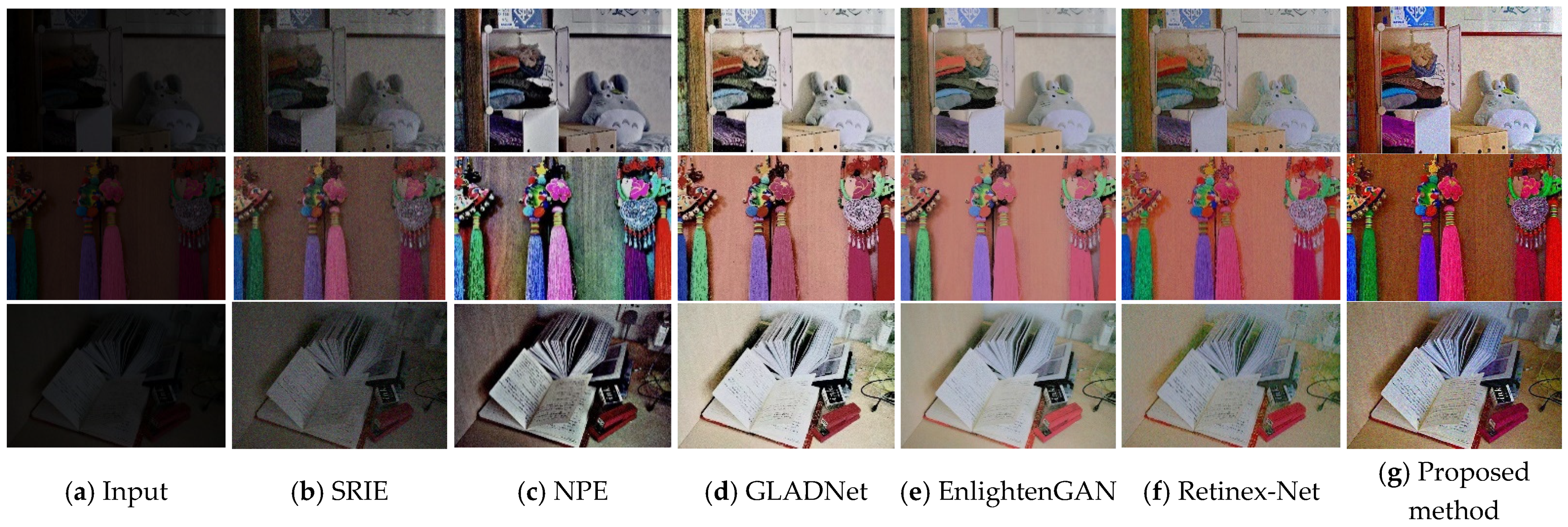
4.3. Comparative Experiment

In this paper, we choose three low-illumination images and use different methods to enhance them. Through subjective comparison, we verify the enhancement effect of our algorithm from the evaluation set of the LOL data set combined with objective evaluation indicators. The enhanced visual effect of different methods is shown in Figure 8.
Figure 8 shows that the brightness enhancement degree of SRIE is limited, which is not enough to meet the visual needs of human eyes. The enhancement results of NPE are also darker, and there are more serious distortions in the brighter local areas. The enhancement results of GLADNet and EnlightenGAN have the problem of low saturation. The enhanced image of Retinex-Net has noise and artifacts, and the problem of image color distortion is more serious. The image enhanced by the proposed method has a balanced overall brightness and retains the image’s details and the original color without local overexposure or artifacts.
To further prove the reliability of the proposed algorithm, we carried out experiments on the validation set of the LOL data set. Table 3 shows a quantitative comparison between the algorithm in this paper and other low illumination enhancement algorithms. It shows that the proposed method is the best in all indicators, and it is significantly improved compared with Retinex-Net, and performs better than the original algorithm. It has certain advantages in reducing noise, enhancing image brightness, and preserving image color.

5. Conclusions

This paper proposed a modified Retinex-Net algorithm. By using an efficient attention mechanism method and constructing information interaction between the attention modules, the performance of attention mechanism can be maximized to a certain extent to ameliorate the network’s learning ability.The denoising loss can effectively suppress noise and retain the essential structure of the image. The color loss restores the image to a more natural color, making the result more robust.The final enhancement result of the proposed algorithm is moderate in brightness, and is not too dark or too bright. The color is natural and not distorted, avoiding artifacts and excessive noise. The objective evaluation indexes such as PSNR and SSIM have also achieved better results. The primary research goal in the future is to improve the running time of the algorithm and to extend it to the task of object detection or object recognition under low light.

Author Contributions

Conceptualization, M.L.; methodology, M.L. and J.C.; software, J.C.; validation, J.C. and X.H.; formal analysis, M.L.; investigation, M.L. and J.C.; resources, M.L. and J.C.; data curation, J.C.; writing—original draft preparation, M.L. and J.C.; writing—review and editing, M.L., J.C.; visualization, J.C. and X.H.; supervision, M.L. All authors have read and agreed to the published version of the manuscript.

Funding

This research received no external funding.

Institutional Review Board Statement

Not applicable.

Informed Consent Statement

This study did not involve humans and chose to exclude this statement.

Data Availability Statement

The data presented in this study are available on request from the corresponding author.

Conflicts of Interest

The authors declare no conflict of interest.

References

  1. Hu, X.; Ma, P.; Mai, Z.; Peng, S.; Yang, Z.; Wang, L. Face hall-ucination from low quality images using definition-scalable inference. Pattern Recognit. 2019, 94, 110–121. [Google Scholar] [CrossRef]
  2. Pan, R.; Zeng, L.; Wum, S.; Wang, R. Feature detection method for low illumination image. Sens. Microsyst. 2021, 40, 110–113+117. [Google Scholar]
  3. Liu, M.; Su, T.; Wang, Y. Companding multiscale Research on Retinex image enhancement algorithm. J. Harbin Univ. Sci. Technol. 2020, 25, 93–99. [Google Scholar]
  4. Jiang, J.L.; Liu, G.M.; Zhu, Z.; Huang, Z.; Zheng, J.Y. Dynamic Multi-Histogram Equalization Based on Fast Fuzzy Clustering. Acta Electron. Sin. 2022, 50, 167–176. [Google Scholar]
  5. Wang, L.; Chang, X.; Ren, W. Color Image Enhancement Simulation Based on Weighted Histogram Equalization. Comput. Simul. 2021, 38, 126–131. [Google Scholar]
  6. Xuan, D.; Guan, W.; Yi, P.; Wen, J. Fast Efficient Algorithm for Enhancement of Low Lighting Video. In Proceedings of the 2011 IEEE International Conference on Multimedia and Expo, Barcelona, Spain, 11–15 July 2011; IEEE: Toulouse, France; pp. 1–6. [Google Scholar]
  7. He, K.; Sun, J.; Tang, X. Single Image Haze Removal Using Dark Channel Prior. IEEE Trans. Pattern Anal. Mach. Intell. 2011, 33, 2341–2353. [Google Scholar] [PubMed]
  8. Land, E.H. The Retinex Theory of Color Vision. Sci. Am. 1978, 237, 108–128. [Google Scholar] [CrossRef] [PubMed]
  9. Yang, J.; Xu, Y.; Yue, H.; Jiang, Z.; Li, K. Low-light image enhancement based on Retinex decomposition and adaptive gamma correction. IET Image Process. 2020, 15, 211–220. [Google Scholar] [CrossRef]
  10. Liu, S.; Long, W.; He, L.; Li, Y.; Ding, W. Retinex-Based Fast Algorithm for Low-Light Image Enhancement. Entropy 2021, 23, 746. [Google Scholar] [CrossRef] [PubMed]
  11. Lore, K.G.; Akintayo, A.; Sarkar, S. LLNet: A Deep Autoencoder Approach to Natural Low-light Image Enhancement. Pattern Recognit. 2017, 61, 650–662. [Google Scholar] [CrossRef] [Green Version]
  12. Wei, C.; Wang, W.; Yang, W.; Liu, J. Deep Retinex Decomposition for Low-Light Enhancement. arXiv. Available online: https://arxiv.org/pdf/1808.04560.pdf (accessed on 11 May 2020).
  13. Ignatov, A.; Kobyshev, N.; Timofte, R.; Vanhoey, K.; Van Gool, L. DSLR-Quality Photos on Mobile Devices with Deep Convolutional Networks. In Proceedings of the IEEE Computer Society, Bochum, Germany, 3–5 July 2017; pp. 3297–3305. [Google Scholar]
  14. Li, J.; Wang, J.; Wan, G.; Li, Z.; Xu, D.; Cao, H.; Zhang, G. A combination of histogram equalization and A new image enhancement algorithm based on MSRCR. J. Xidian Univ. 2014, 41, 103–109. [Google Scholar]
  15. Choi, D.H.; Jang, I.H.; Kim, M.H.; Kim, N.C. Color Image Enhancement Based on Single-Scale Retinex With a JND-Based Nonlinear Filter. In Proceedings of the International Symposium on Circuits and Systems (ISCAS 2007), New Orleans, LA, USA, 27 May 2007; IEEE: New York, NY, USA; pp. 1242–1254. [Google Scholar]
  16. Lin, H.; Shi, Z. Multiscale retinex improvement for nighttime image enhancement. Opt.-Int. J. Light Electron Opt. 2014, 125, 7143–7148. [Google Scholar] [CrossRef]
  17. Rahman, Z.U.; Jobson, D.J.; Woodell, G.A. Retinex processing for automatic image enhancement. Proc. SPIE-Int. Soc. Opt. Eng. 2004, 13, 100–110. [Google Scholar]
  18. Jobson, D.J.; Rahman, Z.; Woodell, G.A. A multiscale retinex for bridging the gap between color images and the human observation of scenes. IEEE Trans. Image Process. 2002, 6, 965–976. [Google Scholar] [CrossRef] [PubMed] [Green Version]
  19. Dabov, K.; Foi, A.; Katkovnik, V.; Egiazarian, K. Image denoising with block-matching and 3D filtering. Proc. SPIE-Int. Soc. Opt. Eng. 2006, 6064, 354–365. [Google Scholar]
  20. Wang, Q.; Wu, B.; Zhu, P.; Li, P.; Zuo, W.; Hu, Q. ECA-Net: Efficient Channel Attention for Deep Convolutional Neural Networks. In Proceedings of the CVF Conference on Computer Vision and Pattern Recognition (CVPR), Seattle, WA, USA, 13–19 June 2020; pp. 11531–11539. [Google Scholar]
  21. Ma, X.; Guo, J.; Tang, S.; Qiao, Z.; Chen, Q.; Yang, Q.; Fu, S. DCANet: Learningconnected attentions for convolutional neural networks. In Proceedings of the 2021 IEEE International Conference on Multimedia and Expo (ICME), Shenzhen, China, 5–9 July 2021; pp. 1–6. [Google Scholar]
  22. Zhao, H.; Gallo, O.; Frosio, I.; Kautz, J. Loss Functions for Image Restoration With Neural Networks. IEEE Trans. Comput. Imaging 2017, 3, 633–640. [Google Scholar] [CrossRef]
  23. Feifan, L.; Bo, L.; Feng, L. Fast Enhancement for Non-Uniform Illumination Images using Light-weight CNNs. In Proceedings of the 28th ACM International Conference on Multimedia, Online, 12 October 2020; Association for Computing Machinery: New York, NY, USA; pp. 1450–1458. [Google Scholar]
  24. Zhang, R.; Zhu, J.Y.; Isola, P.; Geng, X.; Lin, A.S.; Yu, T.; Efros, A.A. Real-time user-guided image colorization with learned deeppriors. ACM Trans. Graph. (TOG) 2017, 36, 121–131. [Google Scholar] [CrossRef]
  25. Lehmann, E.L.; Casella, G. Point Estimation Theory; Beijing China Statistics Press: Beijing, China, 2004; p. 11. [Google Scholar]
  26. Mittal, A.; Moorthy, A.K.; Bovik, A.C. Blind/Referenceless Image Spatial Quality Evaluator. In Proceedings of the 2011 Conference Record of the Forty Fifth Asilomar Conference on Signals, Systems and Computers (ASILOMAR), Pacific Grove, CA, USA, 6–9 November 2011; IEEE: New York, NY, USA; pp. 784–792. [Google Scholar]
  27. Guo, X.; Li, Y.; Ling, H. LIME: Low-light Image Enhancement via Illumination Map Estimation. IEEE Trans. Image Process. 2016, 26, 982–993. [Google Scholar] [CrossRef] [PubMed]
Figure 1. Retinex-Net network structure diagram.
Electronics 11 03695 g001
Figure 2. Renderings of different enhancement algorithms.
Electronics 11 03695 g002
Figure 3. Gray histograms corresponding to different enhancement algorithms.
Electronics 11 03695 g003
Figure 4. ECA-Net module structure diagram.
Electronics 11 03695 g004
Figure 5. Deep Connected Attention (DCA) network structure.
Electronics 11 03695 g005
Figure 6. Improved Decom-Net network.
Electronics 11 03695 g006
Figure 7. Improved Enhance-Net network.
Electronics 11 03695 g007
Figure 8. Comparison of enhancement results of different methods.
Electronics 11 03695 g008
Table 1. Different denoising loss results.
Evaluation IndexL1SSIMMSSSIMMix
PSNR(dB)34.4233.1533.2934.61
SSIM0.95350.95000.95360.9564
FSIM0.97750.97640.97820.9795
Table 2. Ablation experiment results.
Serial NoBasic FrameworkImprovement of the MethodPSNR (dB)SSIM
1Retinex-Net16.76220.5465
2Retinex-Netadd ECA, do not add DCA17.58340.6945
3add ECA, add DCA18.44880.7249
4Retinex-Net+ECA+DCAadd, do not add d n 18.87430.749
5 add   d n , do not add18.96160.7443
6 add   c o l o r ,   add   d n 19.45360.7581
Table 3. The results of different evaluation indicators.
SRIENPEGLADNetEnlightenGANRetinex-NetProposed Method
SSIM0.49770.58420.71150.62600.55940.7581
PSNR (dB)11.855016.803419.382119.230316.773919.4536
NIQE7.28738.25626.17444.5289.73034.2874
LOE5754394934451106417
Publisher’s Note: MDPI stays neutral with regard to jurisdictional claims in published maps and institutional affiliations.

