Article

Design and Analysis of Novel Reconfigurable Monopole Antenna Using Dip Switch and Covering 5G-Sub-6-GHz and C-Band Applications

by
Ali Kadhum Abd
1,
Jamal Mohammed Rasool
1,
Zain-Aldeen S. A. Rahman
2 and
Yasir I. A. Al-Yasir
3,*
1
Department of Communication Engineering, Faculty of Engineering, University of Technology-Iraq, Baghdad 61003, Iraq
2
Department of Electrical Techniques, Technical Institute/Qurna, Southern Technical University, Basra 61016, Iraq
3
Biomedical and Electronics Engineering, Faculty of Engineering and Informatics, University of Bradford, Bradford BD7 1DP, UK
*
Author to whom correspondence should be addressed.
Electronics 2022, 11(20), 3368; https://doi.org/10.3390/electronics11203368
Submission received: 12 September 2022 / Revised: 14 October 2022 / Accepted: 15 October 2022 / Published: 19 October 2022
(This article belongs to the Special Issue RF/Microwave Circuits for 5G and Beyond)

Abstract

:
This study presents a unique frequency-reconfigurable antenna that may be the first to use a dip switch and a bias circuit integrated on the same substrate as the antenna. Such an antenna may be used for many wireless applications, since it is small and versatile enough to operate in several frequency bands with different modes. Printed on a Rogers RT5880 substrate, the suggested structure has a relative permittivity of 2.2, a tangent loss of 0.0009, and a size of 28 × 26.35 × 1.6 mm3. Three-PIN diode switches are inserted between radiating patches. The proposed antenna operates in four modes, covering nine different bands by using three dual bands (i.e., 4.36 and 7.78 GHz, 3.56 and 6.89 GHz, 3 and 6.2 GHz) in MODE 1, MODE 2, and MODE three, respectively, and triple band in MODE 4 (i.e., 2.88, 5.87, and 8.17 GHz). The efficiency of the planned antenna is 97.66%, and the gain varies from 1.38 to 4.89 dBi. The obtained bandwidths at corresponding frequencies range from 5.5 to 31.17%. The suggested structure is modeled in the CSTMWS and the simulated findings are experimentally confirmed. The suggested antenna may be employed in current portable (5G) devices and the IoT.

1. Introduction

The new 5G radio access networks are projected to be able to handle many connections at once due to the rapid development of current wireless communication technologies operating across a broad range of frequencies. Low bandwidth (up to 1 GHz), the middle band (below 6 GHz), and the high bandwidth (millimeter-wave) have been separated by the FCC to allow for 5G [1,2]. Fifth-generation (5G) wireless communications call for novel approaches to miniaturizing and enhancing the functioning of RF components such as antennas [3]. Low bandwidth offers strong 5G coverage, millimeter-wave offers data speeds above 2 Gbps and enormous capacity, and the medium band offers a blend of the two. Superfast data speeds may be achieved by using the 5G millimeter wave band. However, several significant issues must be solved before millimeter-wave mobile communication may be used. Millimeter waves are limited in their range due to atmospheric attenuation. For long-distance, high-data-rate communication systems, sub-6 GHz waves may be a better option than millimeter waves since they travel farther. Technology below 6 GHz will soon convert to 5G before millimeter-wave technology for 5G connectivity is completed. 5G connectivity may be used in urban and rural locations since it can transmit high data speeds across great distances. Reconfigurable antennas are gaining popularity as wireless communication technology advances because they can change their properties to meet the user’s needs [4,5]. With frequency-reconfigurable antennas, you may tune your signal to any desired range of frequencies, allowing for effective use of the available spectrum [6].
The single, distinctive reconfiguration of antennas is the subject of the vast majority of published research [7]. A frequency-reconfigurable hook-shaped antenna was demonstrated in [8] for a variety of applications. An innovative headband antenna for WiFi, WLAN, WiMAX, and UMTS applications has been described in [9]. ISMA low-profile frequency reconfigurable antennas cover ISM, WLAN, WiFi, and Airport Surveillance Radar band applications [10]. WLAN and 5G sub-6 GHz applications offer frequency-reconfigurable antennas [11,12]. For the 5G sub-6 GHz applications addressed in [13], a base station dual-band dual-polarized filtering antenna with good selectivity is suggested. As an alternative, [14] discusses a four-band frequency reconfigurable antenna. As we move toward 5G, the complexity of the RF front end continues to increase [15]. The fast development of communication technology necessitates the use of several antenna configurations for different purposes; PIN diodes for frequency reconfigurability have been extensively studied by researchers to achieve single-band, dual-band, and multiple-band reconfigurable operations [16,17,18,19,20,21,22,23,24,25,26,27,28,29].
In Ref. [16], a wideband antenna for Wireless Wide Area Network (WWAN) and Long-Term Evolution (LTE) applications was designed for sub-6-GHz applications. Despite its modest design, the antenna performed well across a broad range of operating frequencies. Despite this, the antenna had some downsides, including a large size, limited gain, and the inability to be reconfigured. Ref. [17] converted a wideband monopole antenna into a triband antenna for ISM and 5G-sub-6-GHz use. Antennas that use proximity-coupling feeds to cover WLAN and 5G-sub-6 GHz have also been proposed [18,19]. However, these antennas do not provide frequency reconfiguration. The suggested antenna, on the other hand, features a complicated antenna construction comprised of two substrates connected by an air gap. Many single-band frequency reconfigurable antennas have been developed in the frequency ranges of 2–4.5 GHz [19,20,21,22,23,24]. Antennas described in [19,20,21] have very high gain characteristics, but their multilayered constructions increase their thickness and complexity. In Ref. [22], a novel hybrid co-simulation technique was used to create an extremely small microstrip reconfigurable filter for 4G and sub-6 GHz 5G systems. Although the antennas described in [23,24] are small, their bandwidth is extremely limited, making them unsuitable for modern devices that operate in wideband frequency spectrums. Refs. [25,26] present antennas with frequency reconfigurable characteristics for LTE and Wireless Local Area Network (WLAN) applications. For wideband operation, a typical rectangular patch antenna was modified with Defected Ground Structure (DGS) and three-PIN diodes [25].
Ref. [26] used an asymmetric feed and two PIN diodes, as well as a variety of slots, to provide frequency reconfigurability. Despite their small size and simple shape, these antennas have very limited bandwidth in both single- and dual-band modes of operation. Refs. [27,28] described frequency reconfigurable antennas that could go from dual-band to tri-band or from dual-band to quad-band. However, although both works span a wide range of frequencies, they are hindered by their relatively limited bandwidth, intricate geometrical architecture, and very small number of operating modes. Additionally, the bigger dimensions of the antenna shown in [27] are a drawback. For sub-6-GHz applications, Ref. [29] suggested a flexible frequency reconfigurable antenna. With a very basic construction, the submitted work provides wideband and dual-band operating modes.
A compact dimension (28 × 26.35 × 1.6 mm3.) multiband compound reconfigurable antenna with both frequency reconfigurability is reported in this study. The compound reconfigurability is performed using three-PIN diode switches. This research presents a new rogers RT5880 substrate-based frequency reconfigurable multiband antenna design. The suggested antenna is reconfigurable utilizing PIN diode switches and radiates on nine distinct bands with promising gain, radiation efficiency, and small dimensions by using a dip switch to transition between the bands. The proposed antenna can be used with this switching mechanism as a first-stage standard for designing an antenna for cognitive radio and controlling the frequency range by switching the dip switch with an electronic switch that can be controlled by the microcontroller board (Arduino Uno). The proposed antenna comprises three-PIN diode switches. This paper is arranged as follows: Section 2 outlines the design technique and geometry of the proposed switchable multiband antenna. The analysis of simulated and measured data is described in Section 3, and Section 4 concludes this research work.

2. Methodology

The fundamental geometry and theory of design for the proposed multiband frequency reconfigurable antenna are presented in this section. An RLC-equivalent circuit of PIN diodes provides frequency reconfigurability in simulation. The ON/OFF status of the diodes allows the antenna to be operated at various frequencies. Partial ground planes have been found to improve efficiency and provide acceptable results in the distant field.

2.1. Structural Geometry

Figure 1 presents the top, bottom, and side view of the systematic geometry of the proposed frequency reconfigurable antenna. A Rogers RT5880 dielectric (εr = 2.2, tan δ = 0.0009, h = 1.6 mm) is used as the antenna substrate. The antenna is fabricated using standard copper cladding of 0.035 mm thickness. A truncated ground plane of length Lg was used to achieve wideband operational bandwidth. The design also implemented two slots made in the ground plane to increase impedance matching. The PIN diode switches were inserted with a one-millimeter gap between the patches. The antenna is excited by a microstrip line with a width of 4.47 mm and an impedance of 50 Ω. In the simulations, switching is accomplished via a PIN diode (SMP1340-079LF). The same Rogers RT5880 substrate is used to create the biasing circuit for the PIN diode switch. Figure 2 displays a manufacturing model of the suggested antenna and Table 1 shows the precise dimensions.
The effective resonant lengths for intended frequencies are calculated using the transmission line model theory [30]. For the intended operating frequency f, the effective resonant length Lf and effective permittivity εeff are determined by using Equations (1) and (2).
ε e f f = ε r + 1 2 + ε r 1 2 ( 1 + 12 ( w h ) ) 0.5
L f = C v 4 f ε e f f
where Cv represents the velocity of light in a vacuum, εr is the relative permittivity, h is the height or thickness, and w is the width of the substrate.

2.2. Bias Circuit

The biasing circuit for the suggested antenna PIN diode switch is designed on the same Rogers RT5880 substrate. The control of the PIN diode is depicted in Figure 3. For proof of the idea, three switches (PIN diode) are operated by a bias line with a connected bias pad in the biasing circuit. The dip switch works as a switch that operates the diodes by allowing the passage of voltage ON and OFF the diodes, where the dip switch is connected to the negative terminal of the 6-volt DC battery, and the positive end of the battery is directly connected to the bias circuit. When three diodes (D1, D2, and D3) are turned ON, we turn OFF (sw 2 and sw 3), and (sw 4) is on. If we want to turn ON two of the diodes (D1 and D2), we turn OFF (sw 2 and sw 4) and turn ON the (sw 3), and when we want to turn ON (D1) diode, we turn OFF the switches (sw 3 and sw 4); the second switch (sw 2) we keep ON. When using a four-state dip switch, while the actual connection on the bias circuit is three, the fourth (sw 1) connects the positive end of the DC, and we can connect the DC terminal directly as we did, so that the model is scalable to suit future applications, such as cognitive radio. A gap of 1 mm between the patch and bias pad for inductors (H1, H2, H3, and H4) is maintained, as well as a gap of 0.2 mm for a capacitor (C) in the microstrip line, and another gap of 1 mm between two pad lines for resistance (R) 1 Kohm to protect the PIN diode.
The bias circuit used in the proposed model has minimal effects on the antenna because we use inductors of 47 nH that isolate the assumed design from the bias circuit manufactured on the same substrate. Figure 4 shows S-parameter(S11) in the case of the bias circuit and the absence of this circuit. We exclude from the bias circuit these three diodes that are already inserted between patches and touch those patches directly. In addition, when we look at Figure 4, we find that the bias circuit can improve the reflection coefficient, but it remains to maintain the same frequency band and the same bandwidth approximately as is shown in the figure. There is a slight difference, so we neglected the calculations of the bias circuit from the measure of the assumed antenna. The check was carried out using CST.

2.3. Reconfigurability

By altering the ON and OFF states of each PIN diode that provide an open and short circuit behavior between radiating patches, frequency reconfiguration is accomplished in the suggested antenna design. There are nine different modes of operation for the antenna, each with its own set of resonant frequencies. In MODE 1 (D1 to D3 = OFF), the antenna shows dual band behavior and covers 4.36 and 7.78 GHz. For MODE 2 (D1 = ON, D2 and D3 = OFF), the antenna produces two different bands of 3.56 GHz and 6.89 GHz. The antenna also shows dual band behavior and covers 3 and 6.2 GHz in MODE 3 (D1 and D2 = ON, D3 = OFF). The three unique bands of 2.88, 5.87, and 8.17 GHz are covered when the antenna operates in MODE 4 (D1 to D3 = ON). The PIN diodes state at each MODE and the resonant bands related to that MODE are detailed in Table 2.

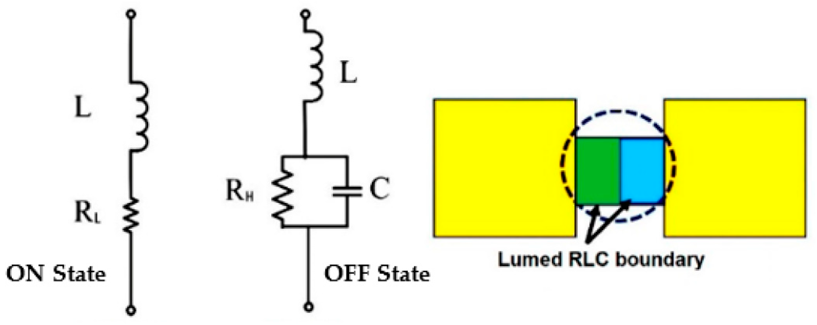
2.4. Switching Techniques

Three-PIN diodes (SMP1340-079LF) are often used for switching since their RF behavior is similar to that of a variable resistor. They are capable of regularly operating in the frequency range of 10 MHz to 10 GHz. As the PIN diodes are inserted, the effective resonant length of the antenna changes, changing the antenna’s operating frequency in the process. These PIN diodes exhibit open and short-circuit behavior. Equivalent circuits for PIN diode switches in both the ON and the OFF states are shown in Figure 5. When in the “ON” position, the circuit is merely made up of a low-value resistor (RL) and an inductor (L). A high-value resistor “RH” is in series with an inductor, and a capacitor (“C”) is in parallel with the other three components. This project makes use of a Skyworks SMP1340-079LF PIN diode. RL = 0.85, L = 0.7 nH, and C = 0.21 pF, according to the datasheet.

3. Results and Discussion

CST Microwave Studio 2021 was used to design and assess the proposed structure. A waveguide port of standard size was allocated to excite the radiating structure. Standard boundary conditions in the CST microwave studio were used to acquire the performance characteristics, such as S-parameter, gain, and surface current plots.

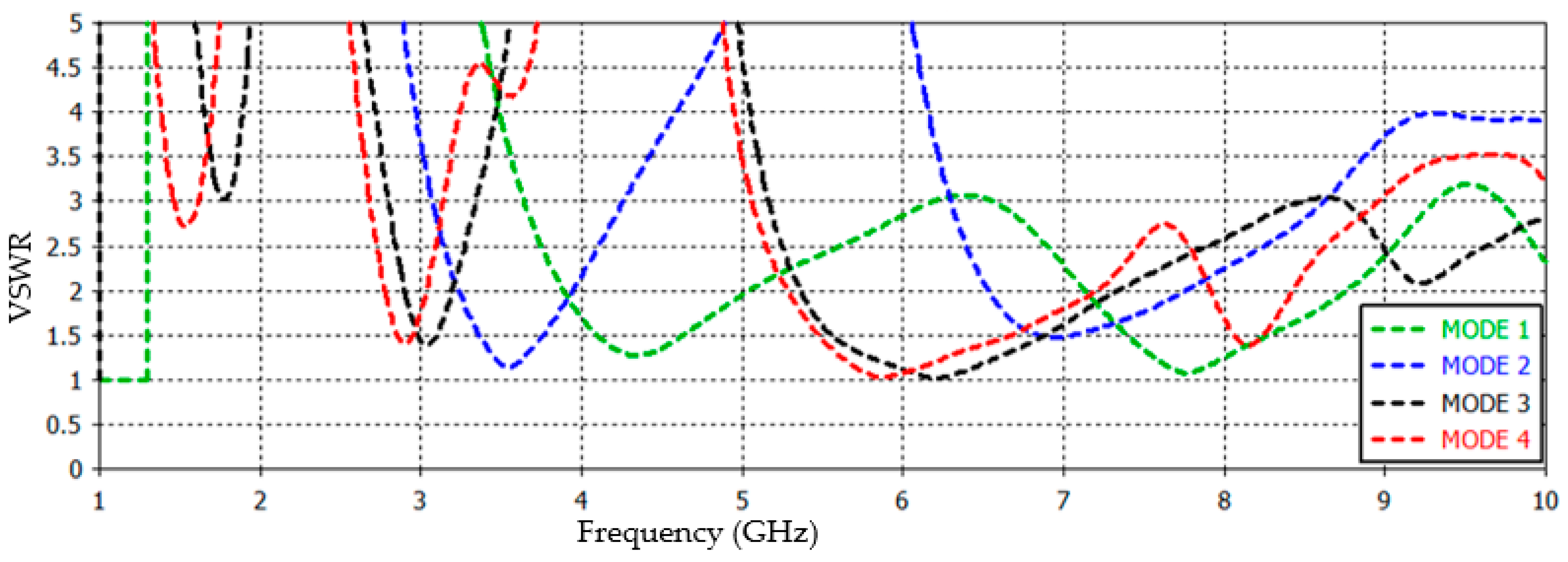
3.1. S-parameter and Bandwidth

Figure 6 depicts the S-parameter of all modes of the suggested antenna. At MODE 1, all switches (D1 to D3) are in the off state; the suggested antenna worked at two different frequency bands, i.e., 4.36, 7.78 GHz with a bandwidth of 1050 MHz (3.92–4.97 GHz) and 1520 MHz (7.18–8.7 GHz), and with−18.37 dB −28.29 dB S-parameter, respectively. In MODE 2 (When D1 is ON), the suggested antenna also resonates with two bands, i.e., 3.56, 6.89 GHz and with −23.5 dB, −14.19 dB S-parameter and bandwidth of 670 MHz (3.26–3.93 GHz) and 1100 MHz (6.59–7.69 GHz), respectively. In MODE 3, the same antenna covers two different bands of 3 and 6.2 GHz; when D1 and D2 are ON, and D3 is OFF, the S-parameter was −14.8 dB and −43.46 dB with a bandwidth of 260 MHz (2.92–3.18 GHz) and 1850 MHz (5.4–7.25 GHz), respectively, at the operating frequencies. When all switches (D1 to D3) are ON, the antenna switches to MODE 4 and operates at 2.88, 5.87, and 8.17 GHz with an S-parameter of −15.17 dB, −35.85 dB, and −15.61 dB with a bandwidth of 230 MHz (2.79–3.02 GHz), 1830 MHz (5.31–7.14 GHz), and 450 MHz (7.94–8.39 GHz), respectively.
The antenna’s feeding line is segregated from the DC path, which is worth emphasizing. Because capacitors may block DC while allowing RF signals to flow, and RF chokes can only block RF and passing DC, a combination of the two is necessary. This work used 47 nH inductors, 10 pF capacitors, and a resistor of 1000 ohm, which were all needed. The resistor is 1000 ohm mounted to limit the voltage across the diode. The biased current is about 10 mA and the biased voltage is 6 V; it is supplied by four alkaline batteries; the reconfigurable monopole antenna’s reflection coefficient (S11) is measured using Agilent Technologies E5071C 30 kHz–20 GHz in Al-Nahrain University as shown in Figure 7a,b.
Figure 8a–d show the simulated and measured S-parameter for each mode. Comparing the measured and simulated findings indicates that they are in good agreement. One of the important things in the case of measurement, especially if we have a reconfigurable antenna test, is that we calibrate the device after each MODE so that the practical results are according to the theoretical ones. For all resonant bands, the antenna’s VSWR (Voltage Standing Waves Ratio) is less than 1.5, indicating optimal driving point impedance matching. Figure 9 shows that the VSWR is less than 2 for all working frequency bands.

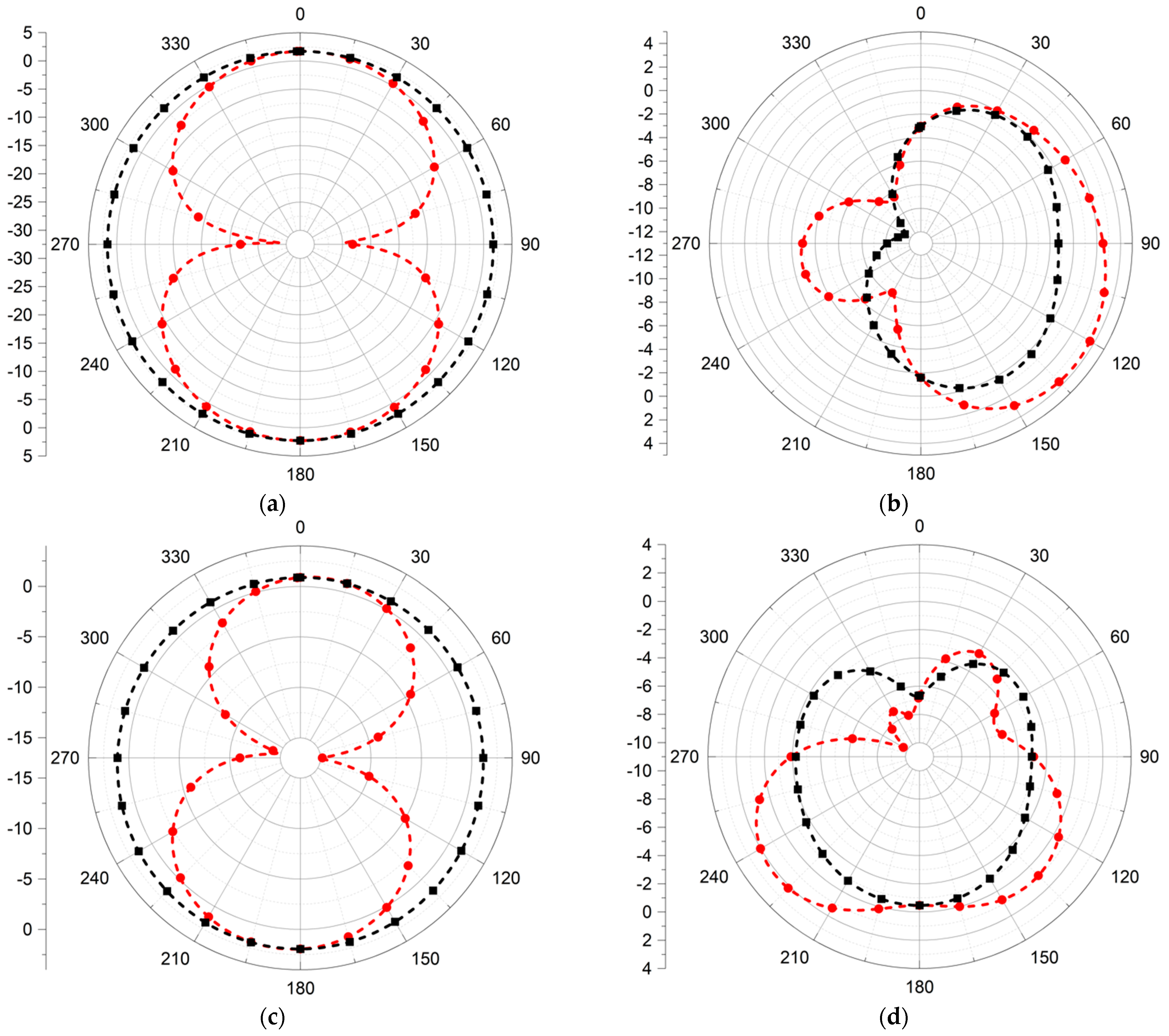
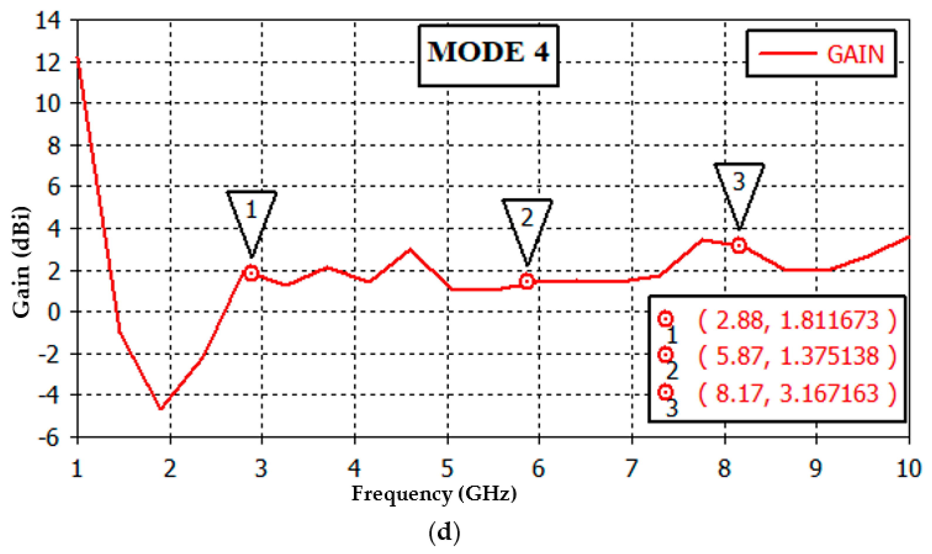
3.2. Far Field Radiation Pattern

In both the H-plane and E-plane at the operating frequency bands, the simulated radiation pattern of the proposed antenna is shown in Figure 10. In the E-plane, the shape of the radiation pattern is a figure-of-eight: Figure 10a at frequency 4.36 GHz, Figure 10c at frequency 3.56 GHz, Figure 10e at frequency 3 GHz and Figure 10g at frequency 2.88 GHz. In most frequency bands, the antenna’s radiation qualities in the H-plane are omnidirectional. In Figure 10b,d,f,h,i, the E-plane is irregular. The suggested antenna operates dual bands 4.36 GHz and 7.78 GHz in MODE 1, depicted in Figure 11a, with a gain of 2.23 dBi and 4.78 dBi with a radiation efficiency of 97.66% and 78.39%, respectively. This is achieved in MODE 2, depicted in Figure 11b, with dual-band 3.56 and 6.89 GHz giving a gain of 2.29 and 2.79 dBi and radiation efficiencies of 88.44% and 70%, respectively.
The antenna worked at 3 and 6.2 GHz in MODE 3, as depicted in Figure 11c; the peak gains were at 1.76 and 2.21 dBi with radiation efficiencies of 95.7% and 80.14%, respectively. With MODE 4 depicted in Figure 11d, the suggested structure worked at 2.88, 5.87, and 8.17 GHz, and peak gains of 1.81, 1.38, and 3.16 dBi with radiation efficiencies were 94.53%, 78.06%, and 82.36%, respectively. Resonant frequencies are shown in three-dimensional gain plots to better understand the antenna’s radiation qualities in Figure 11.

3.3. Surface Currents

Figure 12 depicts the antenna radiating structure’s surface current distribution for several frequency bands. Figure 12a,b depict MODE 1, where the antenna worked in dual-band operations (i.e., 4.36 and 7.78 GHz); the density of the surface currents was higher on the main radiator, which contributes to radiation at 4.36 and 7.78 GHz. Figure 12c–f depict MODE 2 and 3, respectively, where the antenna worked at dual-band operations (i.e., 3.56, 6.89, 3, and 6.2 GHz). In the higher bands, the surface currents imply a dominating contribution from the bigger area of the radiator and a larger surface current density throughout the radiator’s whole length. Figure 12g–i depict MODE 4 (i.e., 2.88, 5.87, and 8.17 GHz), indicating that the entire metallic radiator contributes to radiation in the lower frequency region (i.e., 2.88 GHz). It is worth noting that the radiator’s higher band radiation comes from smaller sections (5.87 and 8.17 GHz). These surface currents indicate that the contributing resonant length for respective frequencies decreases as resonant frequency increases, thus proving the inverse relation of the frequency with resonant length. We note in the current distribution that there is an effect of the bias circuit, as we mentioned earlier, as it improves the reflection coefficient and has less effect on the frequency bands and bandwidth. Performance metrics for the suggested antenna are summarized in Table 3.
The proposed antenna was compared with the published literature; all studies used RT-Rogers Duroid 5880 substrates with εr of 2.2 (dielectric constant) and δ = 0.0009 (loss tangent), with differences in the thickness of the substrates (h): h = 0.508 [31], h = 0.787 [32], h = 0.79 [33], h = 1.6 [34], and h = 1.575 mm [35,36]. Our suggested antenna is more compact than the antennas described in Refs. [31,32,33,34,35,36] in dimensions. With a 230–1850 MHz bandwidth, the proposed antenna has more bandwidth than all antennas constructed in Refs. [31,32,33,34,35,36], has higher gain than Refs. [31,34,36], and has a higher radiation efficiency than antennas designed in Refs. [34,35,36]. Compared to other potential antennas, the most notable difference is that the suggested antenna can function over nine different frequency bands, which is more than any other antenna has been able to do. This comparison is shown in Table 4.

4. Conclusions

This study presents a unique frequency reconfigurable antenna that may be the first to use a dip switch and a bias circuit integrated on the same substrate in a frequency-reconfigurable antenna. The PIN diode switches change the configuration of the reposed antenna. Antenna coverage is limited to a single frequency when all switches are off (4.43 GHz). Dual bands of 3.5 GHz and 5.66 GHz are possible when SW1 is activated. During dual-band operation, the prototype is activated by turning on both SW1 and SW2 (3.1 GHz and 5.5 GHz). When all switches are switched on, the antenna may function at three different frequencies (2.9, 5.14, and 5.7 GHz) simultaneously. In addition to its compact size, low cost, and low weight, the proposed antenna has a wide range of applications, including GSM, UMTS, 4G-LTE, WiMAX, and WLAN Wireless networks, as well as fixed satellite services in the 6 GHz frequency band. The antenna also supports the sub-6GHz 5G bands (2.88, 3, 3.56, 4.36, and 5.87 GHz). The 6 GHz fixed satellite services, as well as IoT-enabled wireless terminals and systems in smart cities, are valuable additions to the small electronic devices that operate at various frequency bands, such as smart cellular devices and tablets.

Author Contributions

Conceptualization, A.K.A. and J.M.R.; methodology, A.K.A.; soft-ware, A.K.A. and J.M.R.; validation, A.K.A. and J.M.R.; formal analysis, A.K.A., J.M.R. and Z.-A.S.A.R.; investigation, A.K.A. and J.M.R.; resources, A.K.A., J.M.R., Z.-A.S.A.R. and Y.I.A.A.-Y.; data curation, A.K.A. and J.M.R.; writing—original draft preparation, A.K.A. and J.M.R.; writing—review and editing, A.K.A., J.M.R. and Z.-A.S.A.R.; visualization, A.K.A., J.M.R. and Z.-A.S.A.R.; supervision, J.M.R. and Y.I.A.A.-Y. All authors have read and agreed to the published version of the manuscript.

Funding

This research received no external funding.

Conflicts of Interest

The authors declare no conflict of interest.

References

  1. Ahmad, I.; Dildar, H.; Khan, W.U.R.; Shah, S.A.A.; Ullah, S.; Ullah, S.; Umar, S.M.; Albreem, M.A.; Alsharif, M.H.; Vasudevan, K. Design and Experimental Analysis of Multiband Compound Reconfigurable 5G Antenna for Sub-6 GHz Wireless Applications. Wirel. Commun. Mob. Comput. 2021, 2021, 5588105. [Google Scholar] [CrossRef]
  2. Rappaport, T.S.; Sun, S.; Mayzus, R.; Zhao, H.; Azar, Y.; Wang, K.; Wong, G.N.; Schulz, J.K.; Samimi, M.; Gutierrez, F. Millimeter wave mobile communications for 5G cellular: It will work! IEEE Access 2013, 1, 335–349. [Google Scholar] [CrossRef]
  3. Al-Yasir, Y.I.A.; Parchin, N.O.; Fares, M.N.; Abdulkhaleq, A.; Bakr, M.S.; Al-Sadoon, M.; Kosha, J.; Abd-Alhameed, R. A Differential-Fed Dual-Polarized High-Gain Filtering Antenna Based on SIW Technology for 5G Applications. In Proceedings of the 14th European Conference on Antennas and Propagation (EuCAP), Copenhagen, Denmark, 15–20 March 2020. [Google Scholar]
  4. Ahmad, I.; Khan, W.U.R.; Dildar, H.; Ullah, S.; Ullah, S.; Mufti, N.; Kamal, B.; Ahmad, T.; Ghaffar, A.; Hussien, M.I. A Pentaband Compound Reconfigurable Antenna for 5G and Multi-Standard Sub-6GHz Wireless Applications. Electronics 2021, 10, 2526. [Google Scholar] [CrossRef]
  5. Al-Yasir, Y.I.A.; Parchin, N.O.; Elfergani, I.; Abd-Alhameed, R.A.; Noras, J.M.; Rodriguez, J.; Al-jzari, A.; Hammed, W.I. A new polarization-reconfigurable antenna for 5G wireless communications. In International Conference on Broadband Communications, Networks and Systems; Springer: Cham, Switzerland, 2018; pp. 431–437. [Google Scholar]
  6. Akyildiz, I.F.; Lee, W.-Y.; Vuran, M.C.; Mohanty, S. NeXt generation/dynamic spectrum access/cognitive radio wireless networks: A survey. Comput. Netw. 2006, 50, 2127–2159. [Google Scholar] [CrossRef]
  7. Ai-Yasir, Y.I.A.; Parchin, N.O.; Alabdullah, A.; Mshwat, W.; Ullah, A.; Abd-Alhameed, R. New Pattern Reconfigurable Circular Disk Antenna Using Two PIN Diodes for WiMax/WiFi (IEEE 802.11a) Applications. In Proceedings of the 16th International Conference on Synthesis, Modeling, Analysis and Simulation Methods and Applica-tions to Circuit Design (SMACD), Lausanne, Switzerland, 15–18 July 2019; pp. 53–56. [Google Scholar]
  8. Iqbal, A.; Smida, A.; Mallat, N.K.; Ghayoula, R.; Elfergani, I.; Rodriguez, J.; Kim, S. Frequency and Pattern Reconfigurable Antenna for Emerging Wireless Communication Systems. Electronics 2019, 8, 407. [Google Scholar] [CrossRef] [Green Version]
  9. Shah, I.; Hayat, S.; Basir, A.; Zada, M.; Shah, S.; Ullah, S. Design and analysis of a hexa-band frequency reconfigurable antenna for wireless communication. AEU Int. J. Electron. Commun. 2018, 98, 80–88. [Google Scholar] [CrossRef]
  10. Iqbal, A.; Smida, A.; Abdulrazak, L.F.; Saraereh, O.A.; Mallat, N.K.; Elfergani, I.; Kim, S. Low-Profile Frequency Reconfigurable Antenna for Heterogeneous Wireless Systems. Electronics 2019, 8, 976. [Google Scholar] [CrossRef] [Green Version]
  11. Jin, G.; Deng, C.; Yang, J.; Xu, Y.; Liao, S. A New Differentially-Fed Frequency Reconfigurable Antenna for WLAN and Sub-6GHz 5G Applications. IEEE Access 2019, 7, 56539–56546. [Google Scholar] [CrossRef]
  12. Jin, G.; Deng, C.; Xu, Y.; Yang, J.; Liao, S. Differential Frequency-Reconfigurable Antenna Based on Dipoles for Sub-6 GHz 5G and WLAN Applications. IEEE Antennas Wirel. Propag. Lett. 2020, 19, 472–476. [Google Scholar] [CrossRef]
  13. Li, Y.; Zhao, Z.; Tang, Z.; Yin, Y. Differentially Fed, Dual-Band Dual-Polarized Filtering Antenna with High Selectivity for 5G Sub-6 GHz Base Station Applications. IEEE Trans. Antennas Propag. 2019, 68, 3231–3236. [Google Scholar] [CrossRef]
  14. Ullah, S.; Ahmad, I.; Raheem, Y.; Ullah, S.; Ahmad, T.; Habib, U. Hexagonal shaped CPW Feed based Frequency Reconfigurable Antenna for WLAN and Sub-6 GHz 5G applications. In Proceedings of the 2020 International Conference on Emerging Trends in Smart Technologies (ICETST), Piscataway, NJ, USA, 26 March 2020; pp. 1–4. [Google Scholar]
  15. Al-Yasir, Y.I.A.; Abdulkhaleq, A.M.; Parchin, N.O.; Elfergani, I.T.; Rodriguez, J.; Noras, J.M.; Abd-Alhameed, R.A.; Rayit, A.; Qahwaji, R. Green and Highly Efficient MIMO Transceiver System for 5G Heterogenous Networks. IEEE Trans. Green Commun. Netw. 2021, 6, 500–511. [Google Scholar] [CrossRef]
  16. Affandi, A.; Azim, R.; Alam, M.; Islam, M.T. A Low-Profile Wideband Antenna for WWAN/LTE Applications. Electronics 2020, 9, 393. [Google Scholar] [CrossRef] [Green Version]
  17. Zaidi, A.; Awan, W.A.; Hussain, N.; Baghdad, A. A Wide and Tri-band Flexible Antennas with Independently Controllable Notch Bands for Sub-6-GHz Communication System. Radioengineering 2020, 29, 44–51. [Google Scholar] [CrossRef]
  18. Ullah, S.; Ahmad, S.; Khan, B.A.; Flint, J.A. A multi-band switchable antenna for Wi-Fi, 3G Advanced, WiMAX, and WLAN wireless applications. Int. J. Microw. Wirel. Technol. 2018, 10, 991–997. [Google Scholar] [CrossRef]
  19. Cai, Y.-M.; Li, K.; Yin, Y.; Gao, S.; Hu, W.; Zhao, L. A Low-Profile Frequency Reconfigurable Grid-Slotted Patch Antenna. IEEE Access 2018, 6, 36305–36312. [Google Scholar] [CrossRef]
  20. Wang, J.; Yang, L. A compact four bands microstrip patch antenna with coplanar waveguide feed. In Proceedings of the 2014 3rd Asia-Pacific Conference on Antennas and Propagation, Harbin, China, 26–29 July 2014; pp. 33–36. [Google Scholar]
  21. Zhu, H.L.; Cheung, S.W.; Liu, X.H.; Cao, Y.F.; Yuk, T.I. Frequency reconfigurable slot antenna using metasurface. In Proceedings of the 8th European Conference on Antennas and Propagation (EuCAP 2014), The Hague, The Netherlands, 6–11 April 2014. [Google Scholar]
  22. Al-Yasir, Y.; Parchin, N.O.; Tu, Y.; Abdulkhaleq, A.; Elfergani, I.; Rodriguez, J.; Abd-Alhameed, R. A Varactor-Based Very Compact Tunable Filter with Wide Tuning Range for 4G and Sub-6 GHz 5G Communications. Sensors 2020, 20, 4538. [Google Scholar] [CrossRef] [PubMed]
  23. Zhao, X.; Riaz, S. A Dual-Band Frequency Reconfigurable MIMO Patch-Slot Antenna Based on Reconfigurable Microstrip Feedline. IEEE Access 2018, 6, 41450–41457. [Google Scholar] [CrossRef]
  24. Soltanpour, M.; Fakharian, M. Compact filtering slot antenna with frequency agility for Wi-Fi/LTE mobile applications. Electron. Lett. 2016, 52, 491–492. [Google Scholar] [CrossRef]
  25. Han, L.; Wang, C.; Chen, X.; Zhang, W. Compact Frequency-Reconfigurable Slot Antenna for Wireless Applications. IEEE Antennas Wirel. Propag. Lett. 2016, 15, 1795–1798. [Google Scholar] [CrossRef]
  26. Biradar, T.A.; Biradar, R.C. A Compact Hexagonal Slot Dual Band Frequency Reconfigurable Antenna for Wlan Applications. Microw. Opt. 2017, 59, 958–964. [Google Scholar]
  27. Abdulraheem, Y.I.; Oguntala, G.A.; Abdullah, A.S.; Mohammed, H.J.; Ali, R.A.; Abd-Alhameed, R.A.; Noras, J.M. Design of frequency reconfigurable multiband compact antenna using two PIN diodes for WLAN/WiMAX applications. IET Microw. Antennas Propag. 2017, 11, 1098–1105. [Google Scholar] [CrossRef]
  28. Ali, T.; Khaleeq, M.M.; Biradar, R.C. A multiband reconfigurable slot antenna for wireless applications. AEU Int. J. Electron. Commun. 2018, 84, 273–280. [Google Scholar] [CrossRef]
  29. Saraswat, K.; Harish, A.R. Flexible dual-band dual-polarised CPW-fed monopole antenna with discrete-frequency reconfigurability. IET Microw. Antennas Propag. 2019, 13, 2053–2060. [Google Scholar] [CrossRef]
  30. Balanis, C.A. Antenna Theory Analysis and Design, 4th ed.; John Wiley & Sons, Inc.: Hoboken, NJ, USA, 2015. [Google Scholar]
  31. Hassan, M.U.; Arshad, F.; Naqvi, S.I.; Amin, Y.; Tenhunen, H. A Compact Flexible and Frequency Reconfigurable Antenna for Quintuple Applications. Radioengineering 2017, 26, 655–661. [Google Scholar] [CrossRef]
  32. Ramli, N.; Ali, M.T.; Yusof, A.L.; Kayat, S.M.; Alias, H.; Sulaiman, M.A. A Reconfigurable Stacked Patch Microstrip Array Antenna (RSPMAA) for Long Term Evolution (LTE) and WiMAX applications. In Proceedings of the 2013 10th International Conference on Electrical Engineering/Electronics, Computer, Telecommunications and Information Technology, Krabi, Thailand, 15–17 May 2013. [Google Scholar]
  33. Kumar, A.; Sharma, M.M. A quad-band reconfigurable microstrip-fed circular disc monopole antenna for multiradio wireless systems. In Proceedings of the 2016 Asia-Pacific Microwave Conference (APMC), New Delhi, India, 5–9 December 2016. [Google Scholar]
  34. Paga, P.; Nagaraj, H.C.; Rukmini, T.S. Design of a dual band frequency reconfigurable monopole antenna using a circular split ring resonator for Wi-Fi and Wi-Max applications. In Proceedings of the 2017 International conference of Electronics, Communication and Aerospace Technology (ICECA), Coimbatore, India, 20–22 April 2017. [Google Scholar]
  35. Qin, J.; Fu, X.; Sun, M.; Ren, Q.; Chen, A. Frequency Reconfigurable Antenna Based on Substrate Integrated Waveguide for S-Band and C-Band Applications. IEEE Access 2020, 9, 2839–2845. [Google Scholar] [CrossRef]
  36. Shahgholi, A.; Moradi, G.; Abdipour, A. Low-Profile Frequency-Reconfigurable LTE-CRLH Antenna for Smartphones. IEEE Access 2020, 8, 26487–26494. [Google Scholar] [CrossRef]
Figure 1. The suggested antenna geometry.
Electronics 11 03368 g001
Figure 2. Prototype antenna structure: top and bottom view.
Electronics 11 03368 g002
Figure 3. The fabrication of the suggested antenna and biasing circuit.
Electronics 11 03368 g003
Figure 4. S11 in the case of the bias circuit and the absence of this circuit.
Electronics 11 03368 g004
Figure 5. The equivalent circuits of the PIN diode and its CST model.
Electronics 11 03368 g005
Figure 6. S 11 for all operating modes in the antenna.
Electronics 11 03368 g006
Figure 7. The reflection coefficient: (a) setup of antenna used to determine the reflection coefficient of (S11), (b) S11 measured using Agilent Technologies E5071C.
Electronics 11 03368 g007
Figure 8. The simulated and measured S-parameter occurs in all operational modes: (a) MODE 1, 4.36 and 7.78 GHz. (b) MODE 2, 3.56 and 6.89 GHz. (c) MODE 3, 3 and 6.2 GHz. (d) MODE 4, 2.88, 5.87, and 8.17 GHz.
Electronics 11 03368 g008
Figure 9. VSWR of the proposed antenna in different operating modes.
Electronics 11 03368 g009
Figure 10. Simulation results of the radiation pattern of the proposed antenna at different frequencies and switching states; (a) 4.36 GHz (MODE 1), (b) 7.78 GHz (MODE 1), (c) 3.56 GHz (MODE 2), (d) 6.89 GHz (MODE 2), (e) 3 GHz (MODE 3), (f) 6.2 GHz (MODE 3), (g) 2.88 GHz (MODE 4), (h) 5.87 GHz (MODE 4) and (i) 8.17 GHz (MODE 4).
Electronics 11 03368 g010aElectronics 11 03368 g010b
Figure 11. The two-dimensional gain pattern plots for the antenna at frequencies (a) 4.36 GHz, 7.78 GHz (MODE 1), (b) 3.56 GHz, 6.89 GHz (MODE 2), (c) 3 GHz, 6.2 GHz (MODE 3), (d) 2.88 GHz, 5.87 GHz, and 8.17 GHz (MODE 4).
Electronics 11 03368 g011aElectronics 11 03368 g011b
Figure 12. The surface current of the proposed antenna in various modes (a) 4.36 GHz (MODE 1), (b) 7.78 GHz (MODE 1), (c) 3.56 GHz (MODE 2), (d) 6.89 GHz (MODE 2), (e) 3 GHz (MODE 3), (f) 6.2 GHz (MODE 3), (g) 2.88 GHz (MODE 4), and (h) 5.87 GHz (MODE 4) and (i) 8.17 GHz (MODE 4).
Electronics 11 03368 g012aElectronics 11 03368 g012b
Table 1. The suggested optimum antenna parameters.
ParametersValue (mm)ParametersValue (mm)
Ls28L33.25
Ws26.35L42
Lg7L58.5
Wg 20.7L62
Lc 1W112
Wc4.5W22.5
Lf 13W33.995
Wf 4.47W42
L12W52.25
Table 2. The proposed antenna tuning states.
MODESD1D2D3Frequency Band (GHz)
1OFFOFFOFF4.36 and 7.78
2ONOFFOFF3.56 and 6.89
3ONONOFF3 and 6.2
4ONONON2.88, 5.87 and 8.17
Table 3. Summary of antenna results.
ParametersD (1,2,3)
OFF MODE 1
D (1 ON and
2,3 OFF) MODE 2
D (1,2 ON and 3 OFF) MODE 3D (1,2,3) ON MODE 4
Frequencies (GHz)4.367.783.566.8936.22.885.878.17
Gain (dBi)2.234.782.292.791.762.211.811.383.16
S-parameter−18.37−28.29−23.5−14.19−14.8−43.46−15.17−35.85−15.61
Directivity (dBi)2.355.942.523.82.172.992.242.463.96
VSWR1.271.081.141.491.441.011.421.031.39
Bandwidth%24.0819.5318.8215.968.6629.837.9831.175.50
Efficiencies%97.6678.3988.447095.780.1494.5378.0682.36
Table 4. The comparison between our antenna and other antennas.
ReferenceDimensions
(mm3)
Total No of
Operating Bands
Operating
Frequencies (GHz)
Bandwidth
(MHz)
Peak Gains
(dBi)
Radiation
Efficiency (%)
[31]30 × 28.454.2, 4.3, 5.1, 5.5, 7.5600–10002.57–4.2794.8–98.8
[32]55 × 5622.64, 3.5269.5–76.59.14–10.4994.9–98.1
[33]40 × 3042.3, 3.89, 4.96, 5.7110–6501.85–5.5496.2–97.83
[34]35 × 3522.4, 3.5150–3000.14–2.9
[35]53.5 × 53.525.86, 2.41618–3222.37–6.7470–90
[36]53 × 3532.45, 3.50, 5.20147–18201.7–3.485–90
Current
work
28 × 26.3592.88, 3, 3.56, 4.36, 5.87, 6.2, 6.89, 7.78, 8.17230–18501.38–4.7870–97.66
Publisher’s Note: MDPI stays neutral with regard to jurisdictional claims in published maps and institutional affiliations.

