
Eight-Element Antenna Array with Improved Radiation Performances for 5G Hand-Portable Devices


Abstract
:1. Introduction
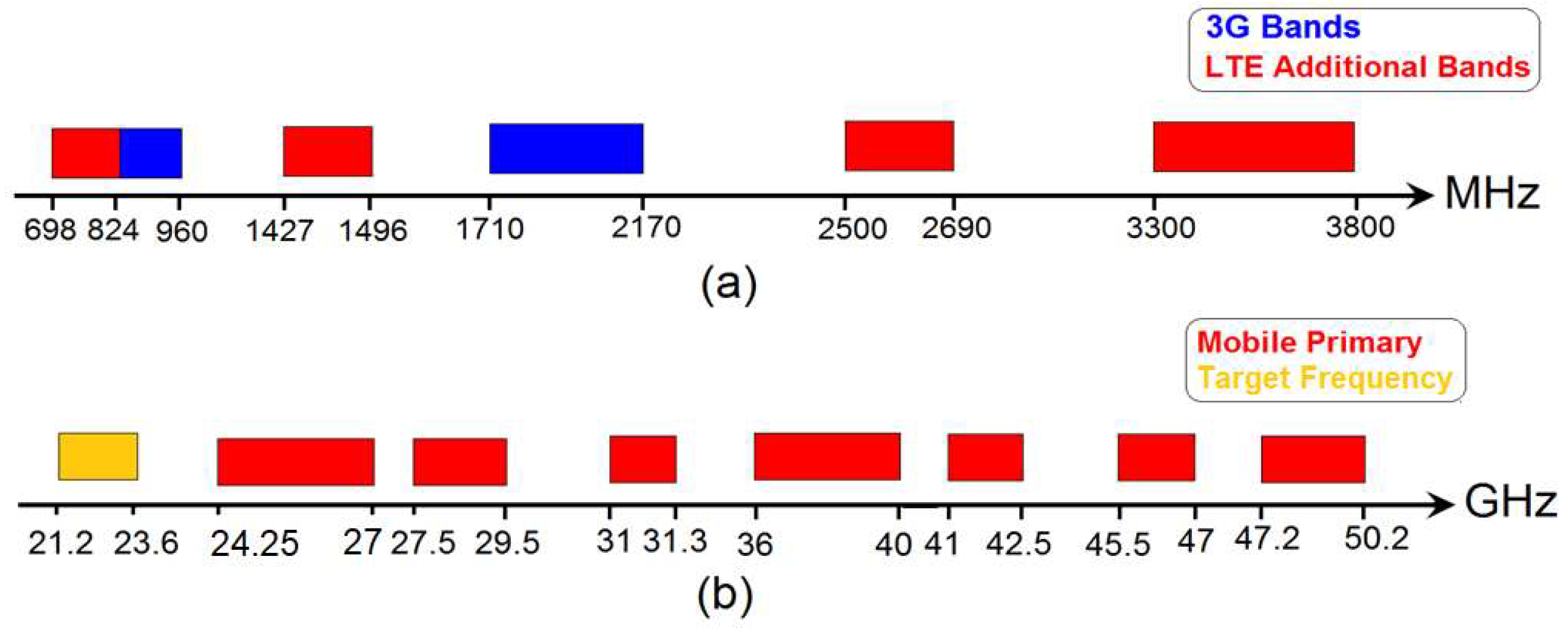
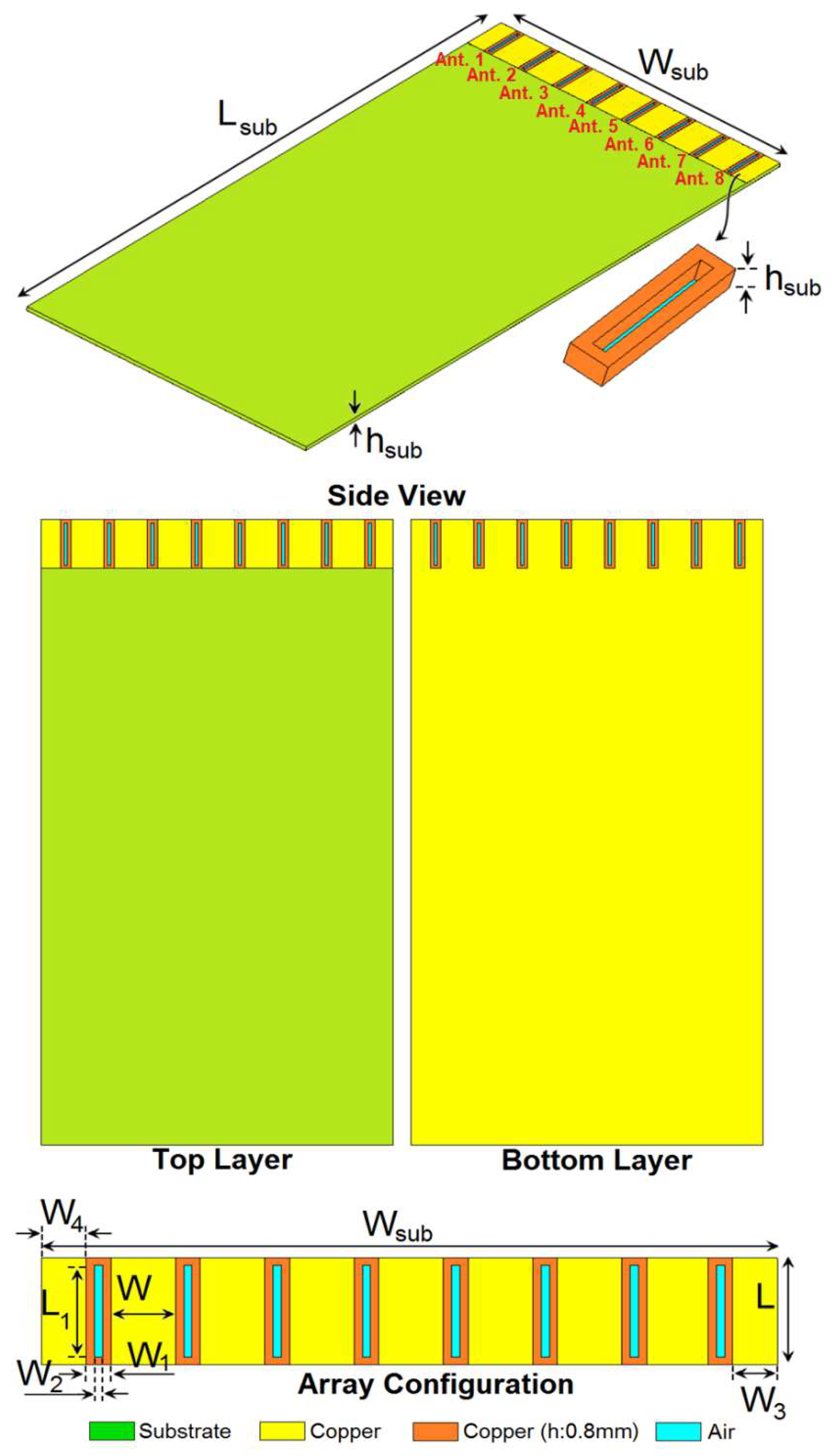
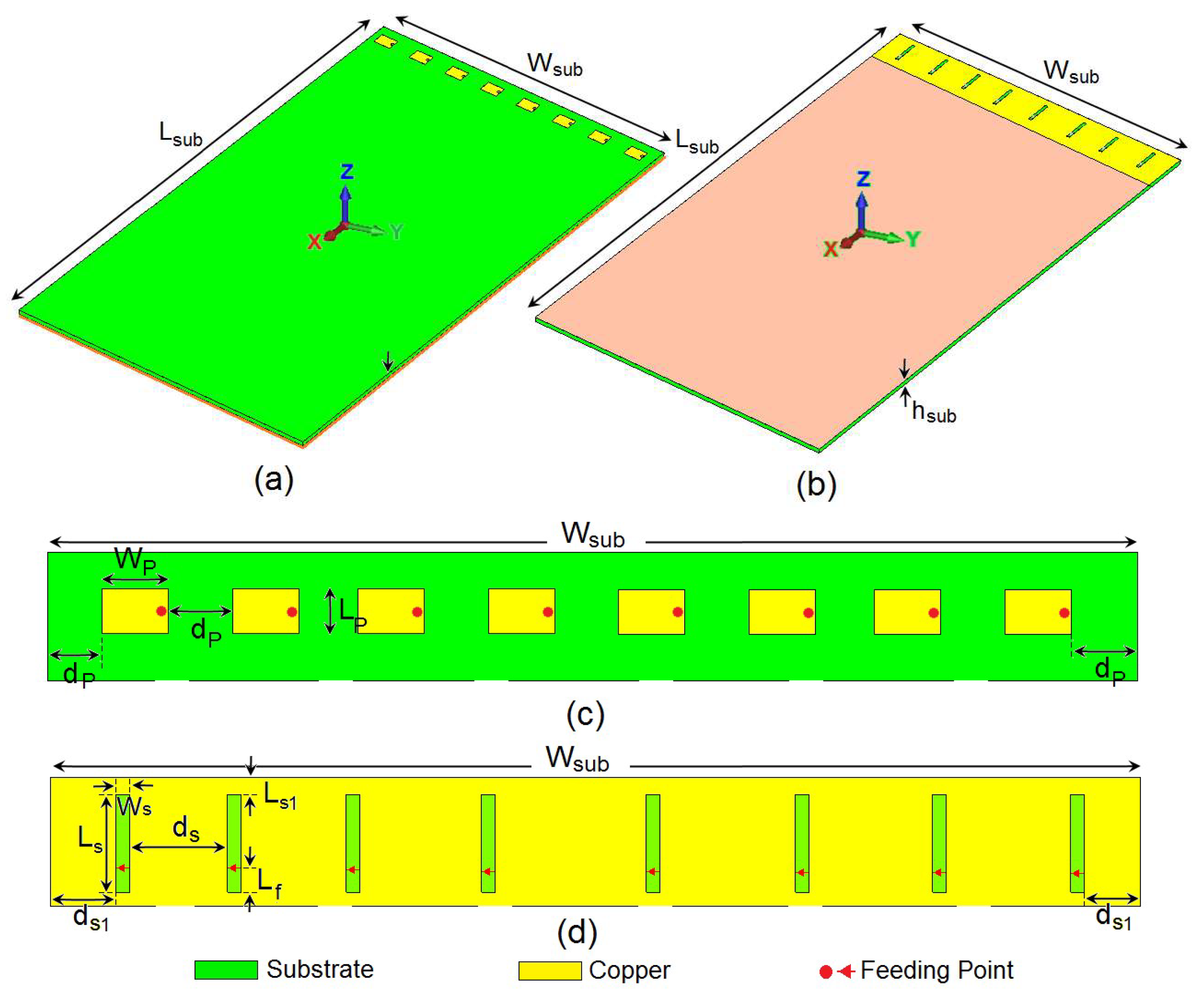
2. Antenna Design
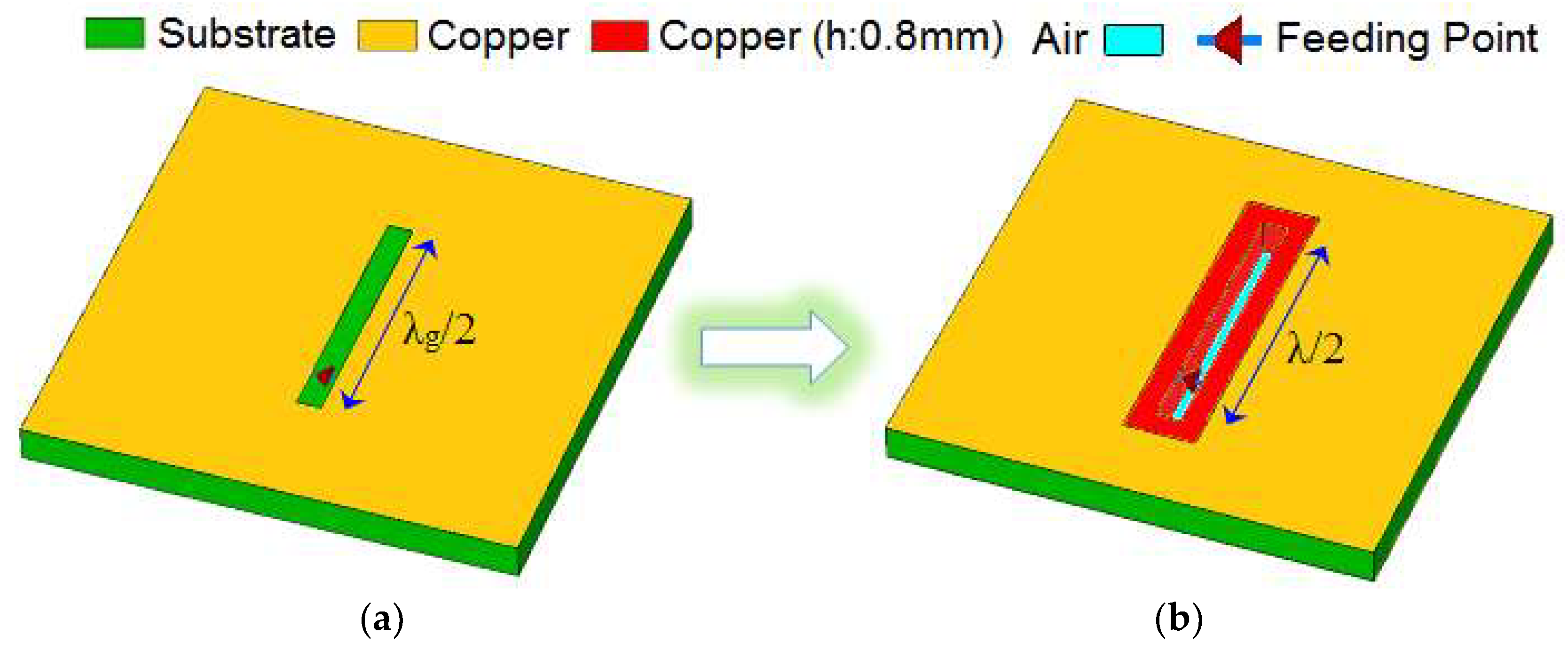
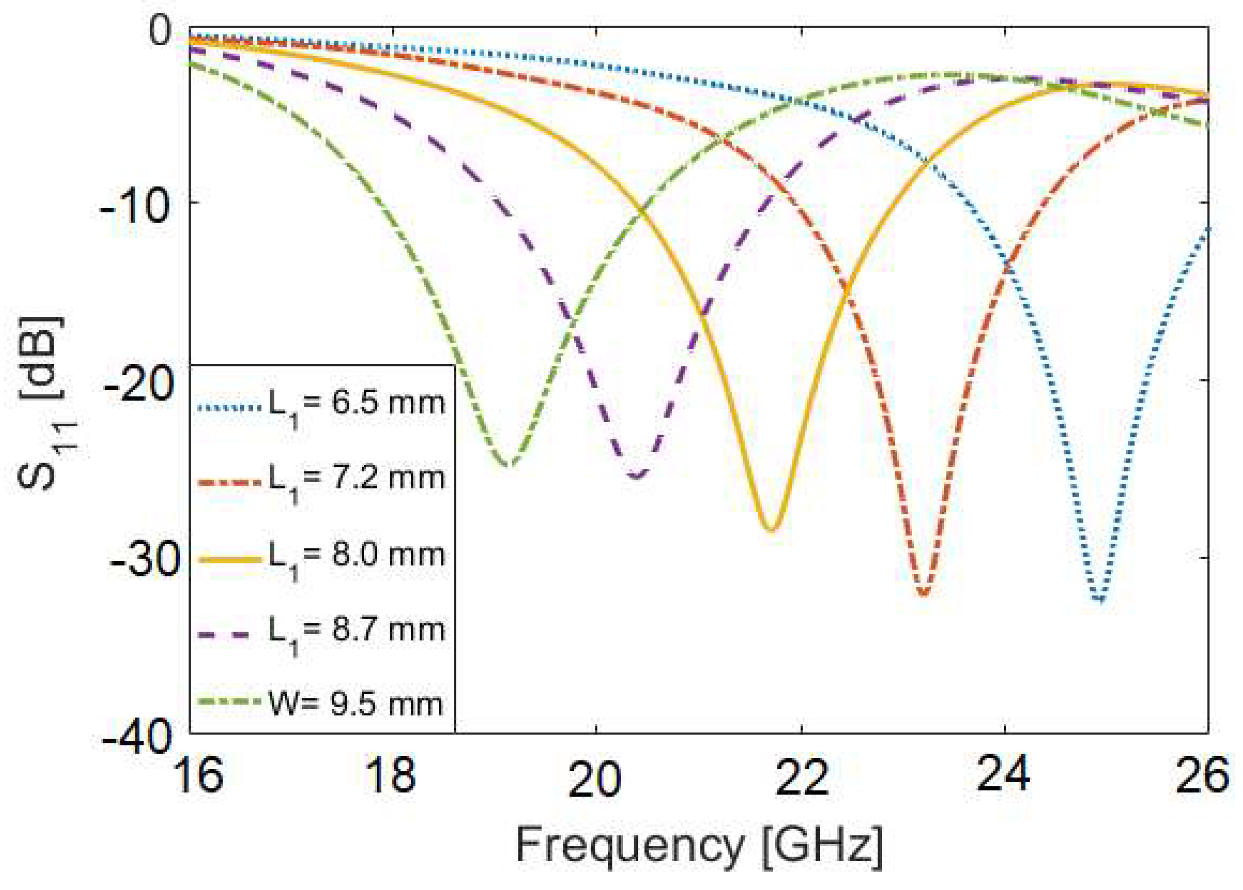
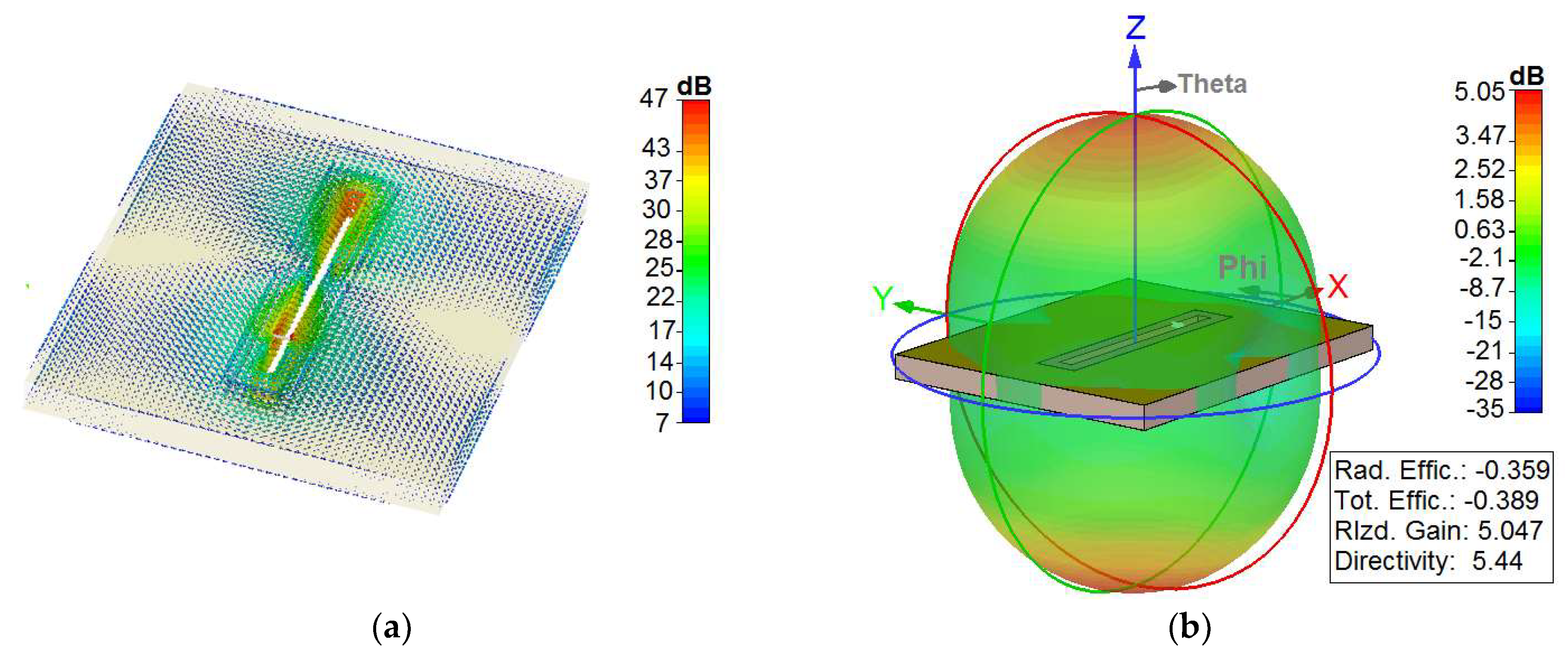
3. Single-Element Antenna
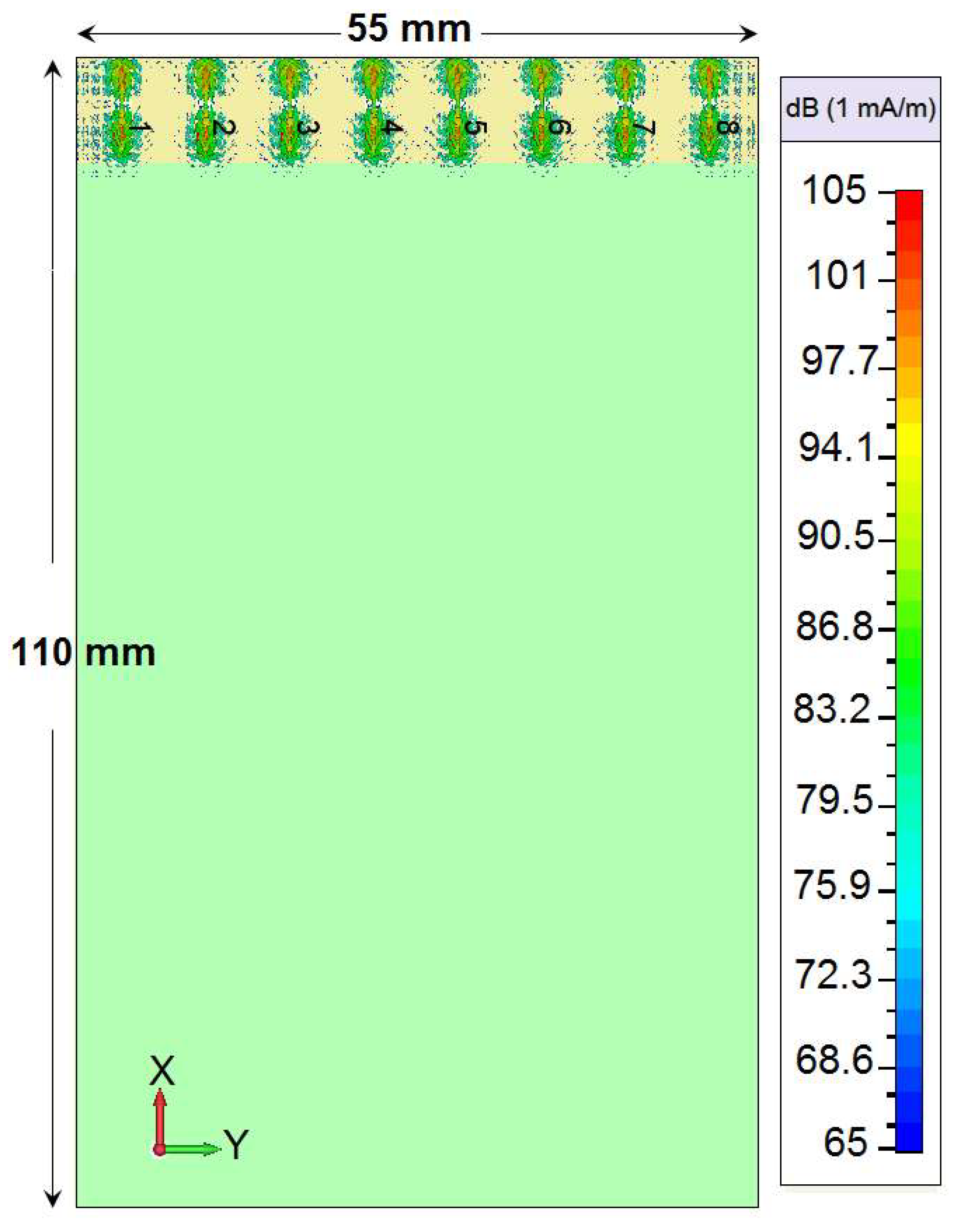
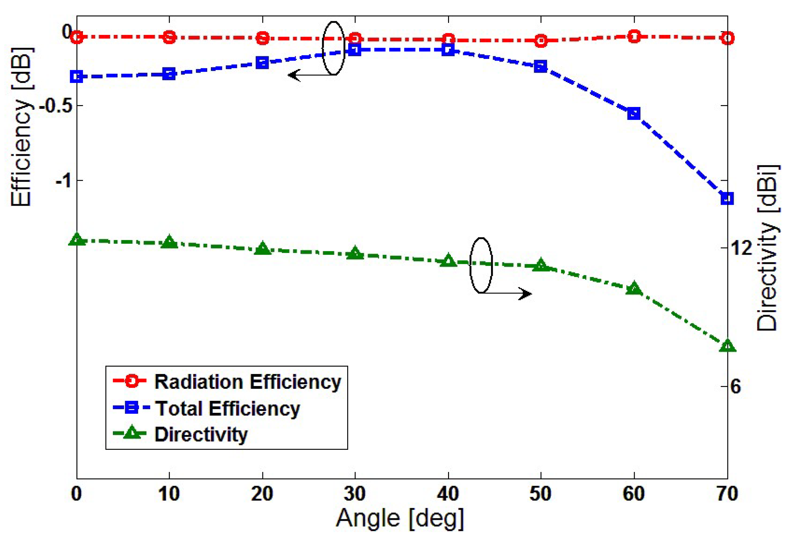
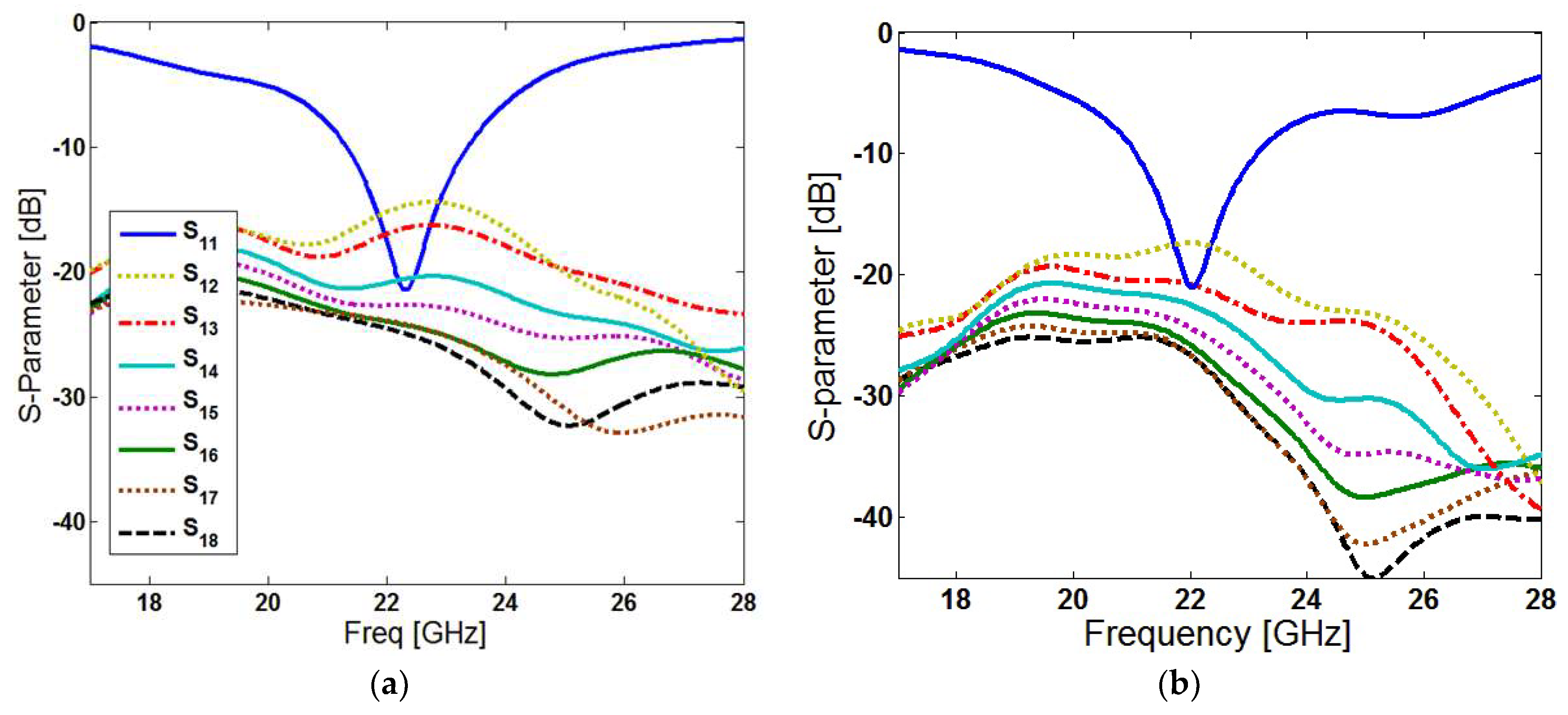
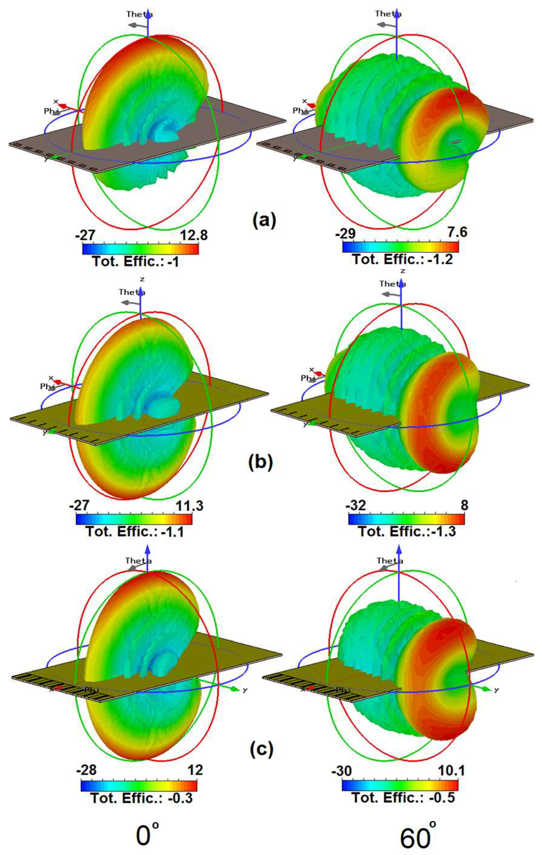
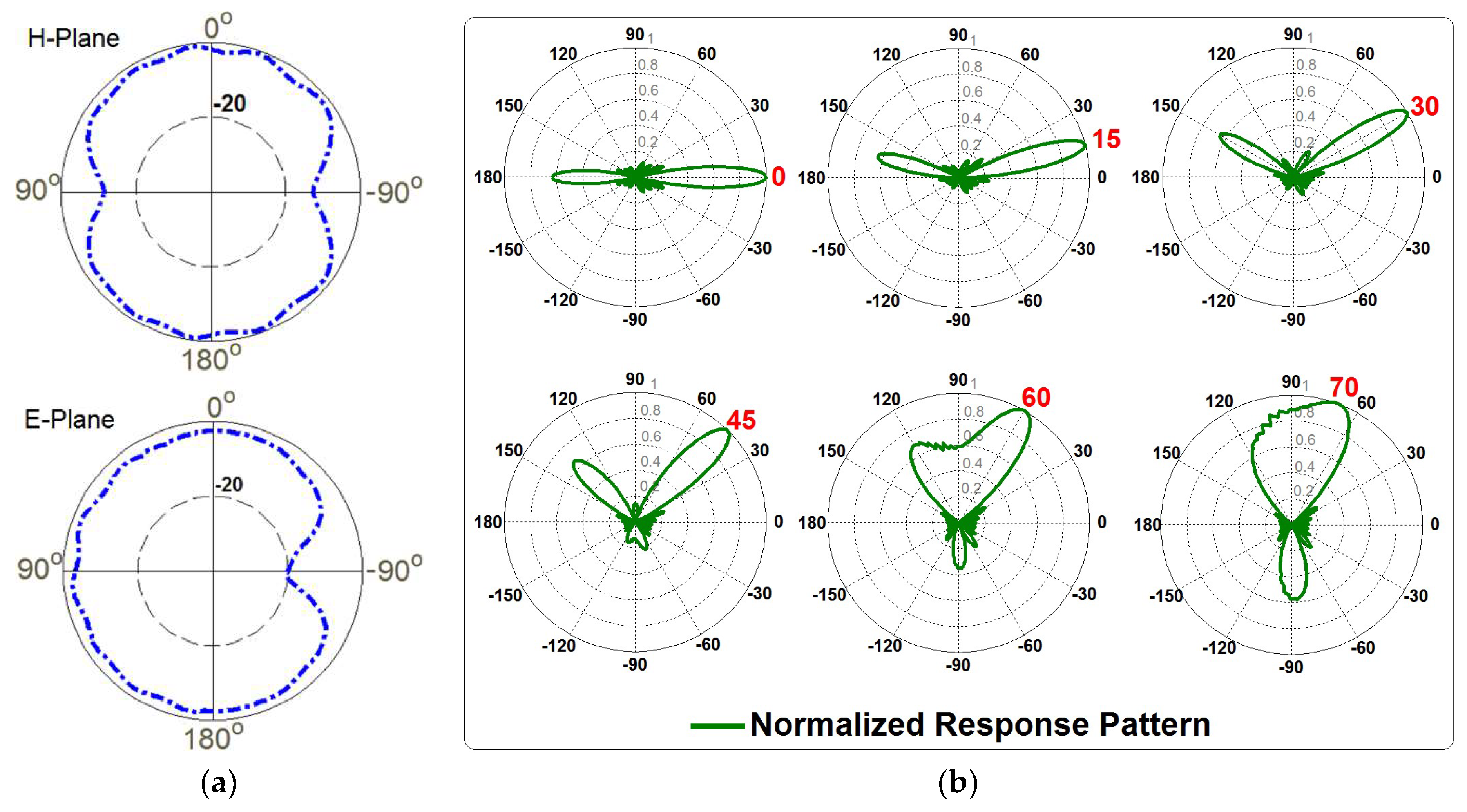
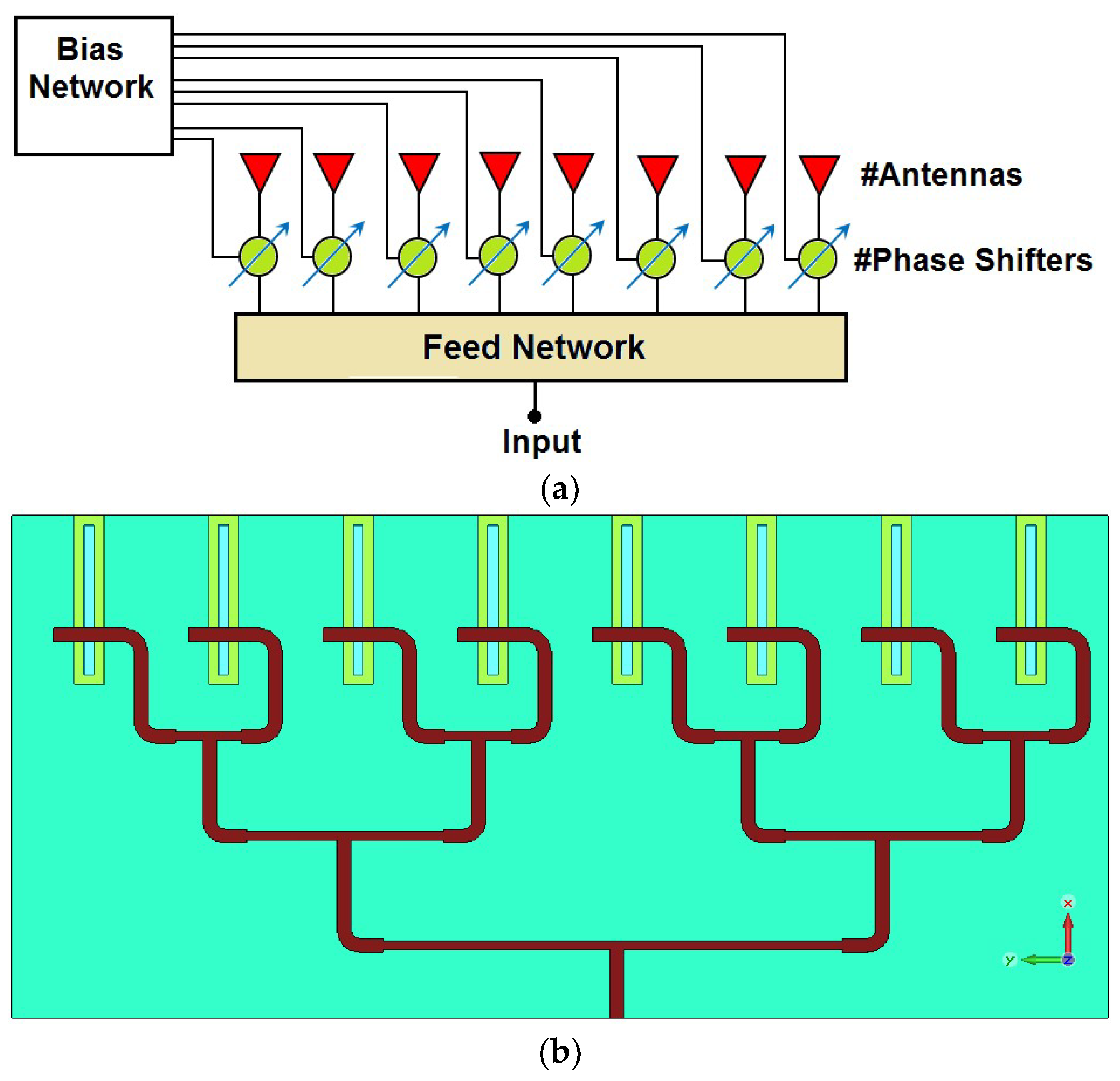
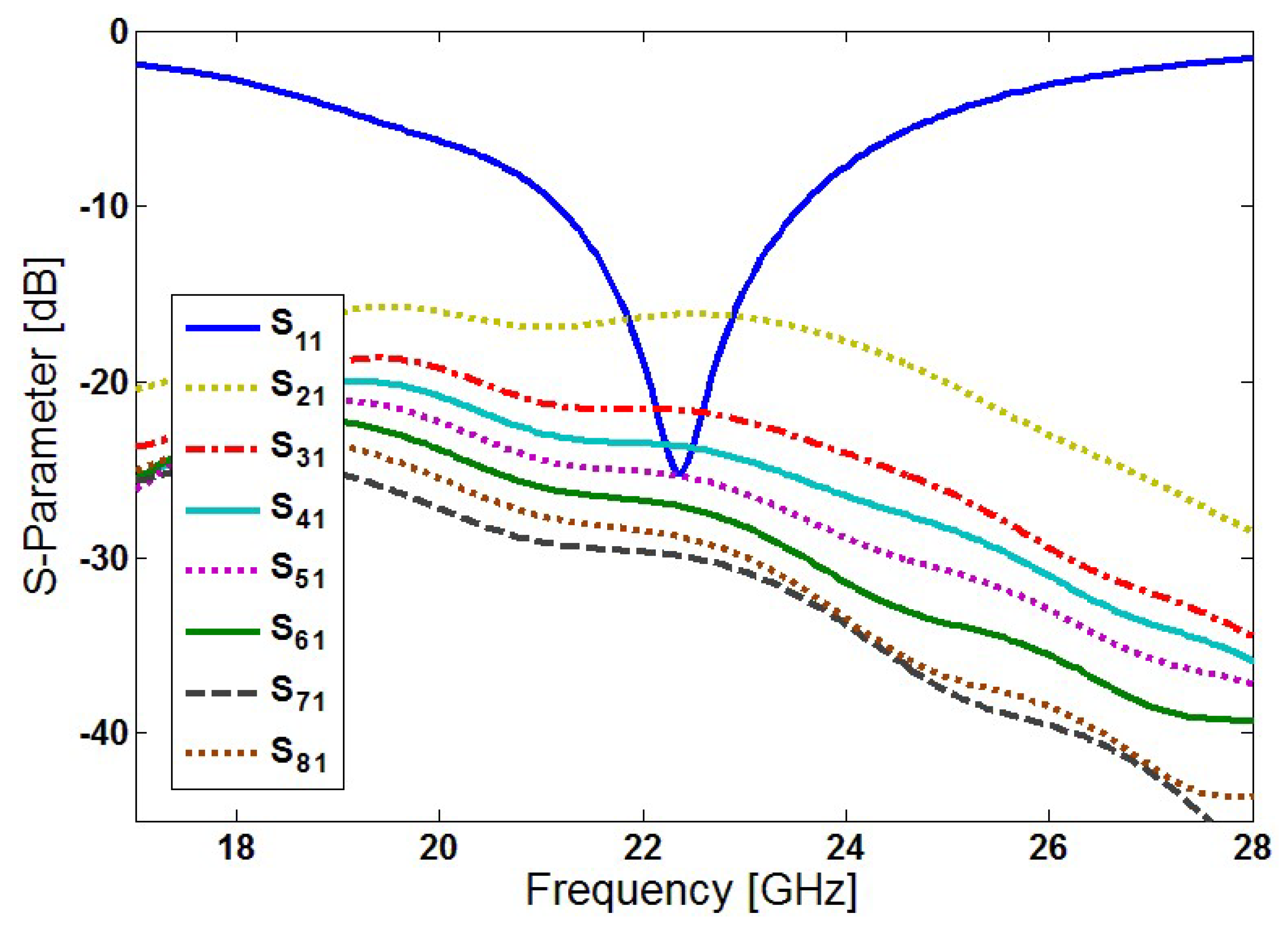
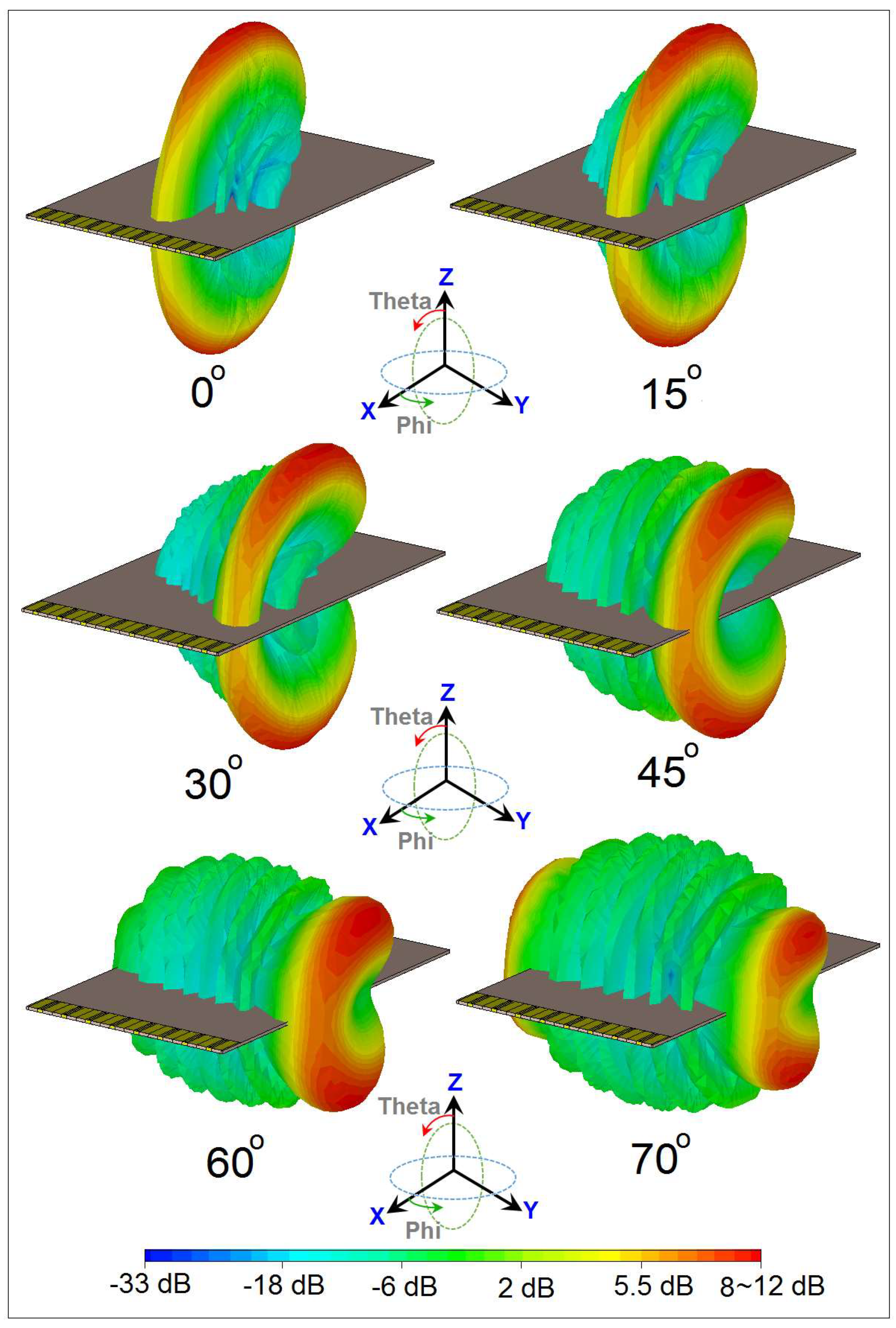
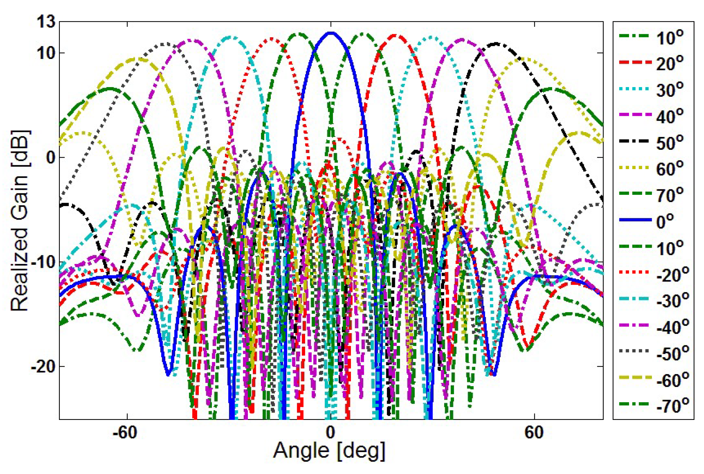
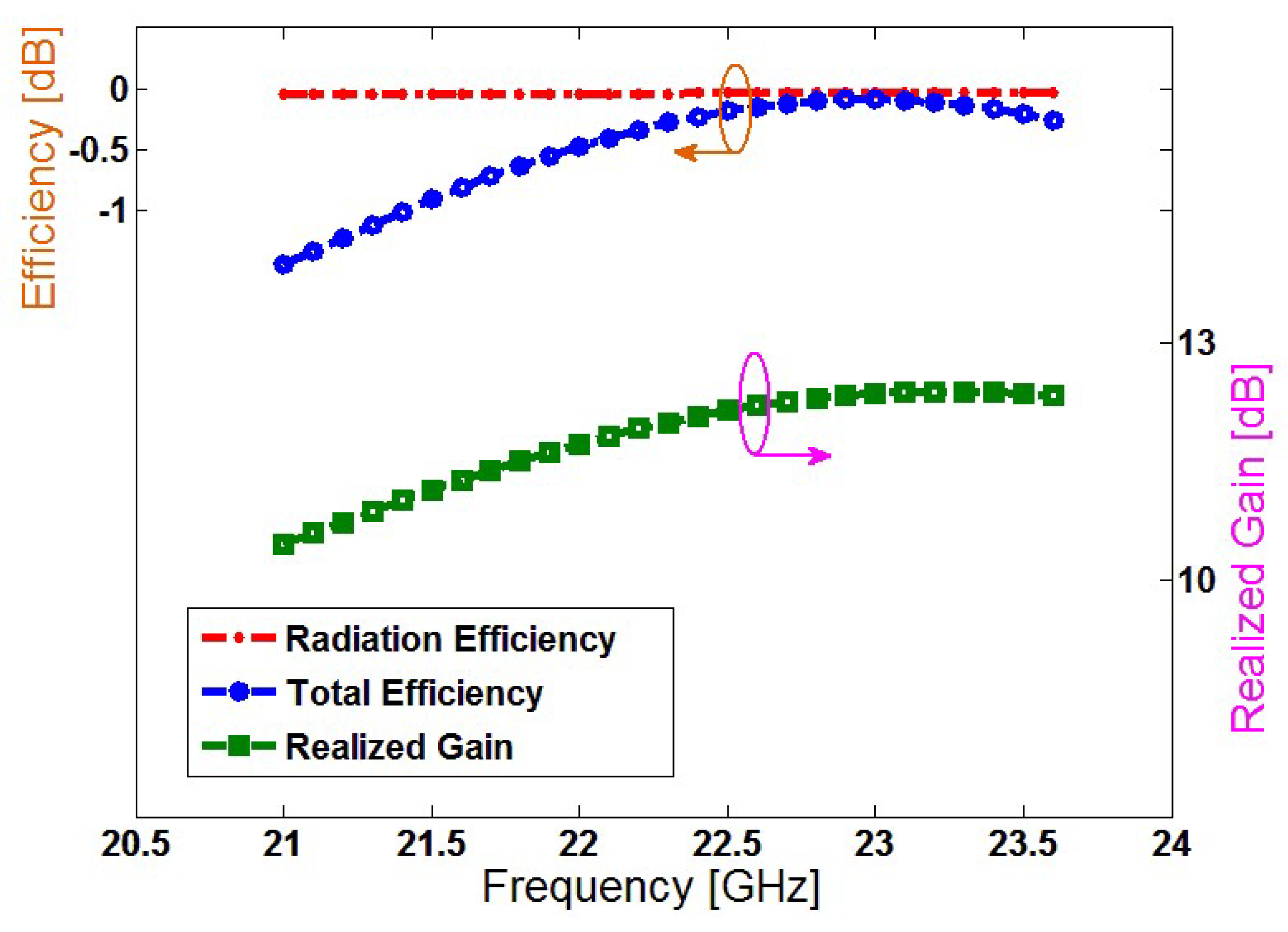
4. Characteristics of the 5G Smartphone Antenna Array
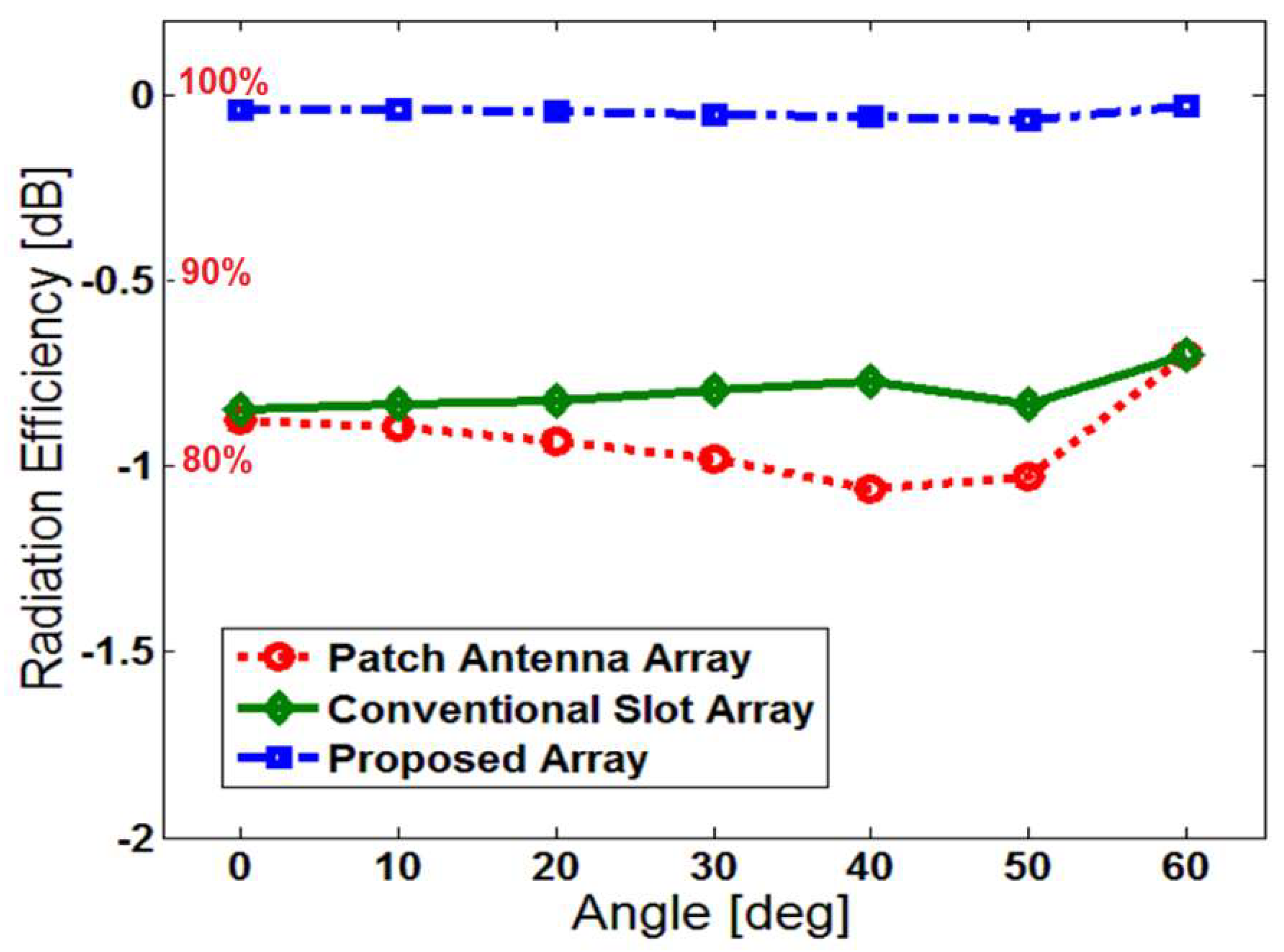
5. Comparison of the Proposed Design with the Conventional Arrays
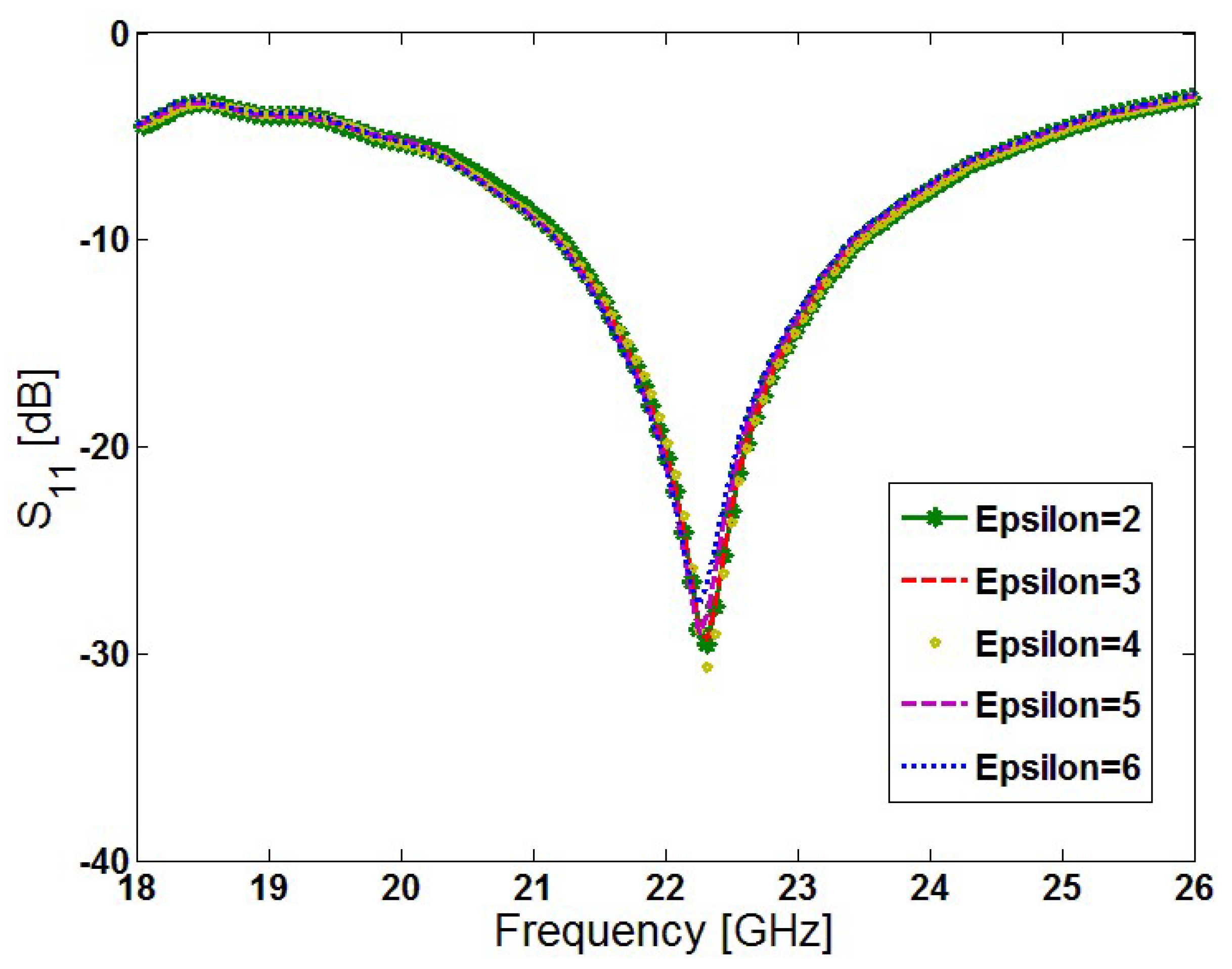
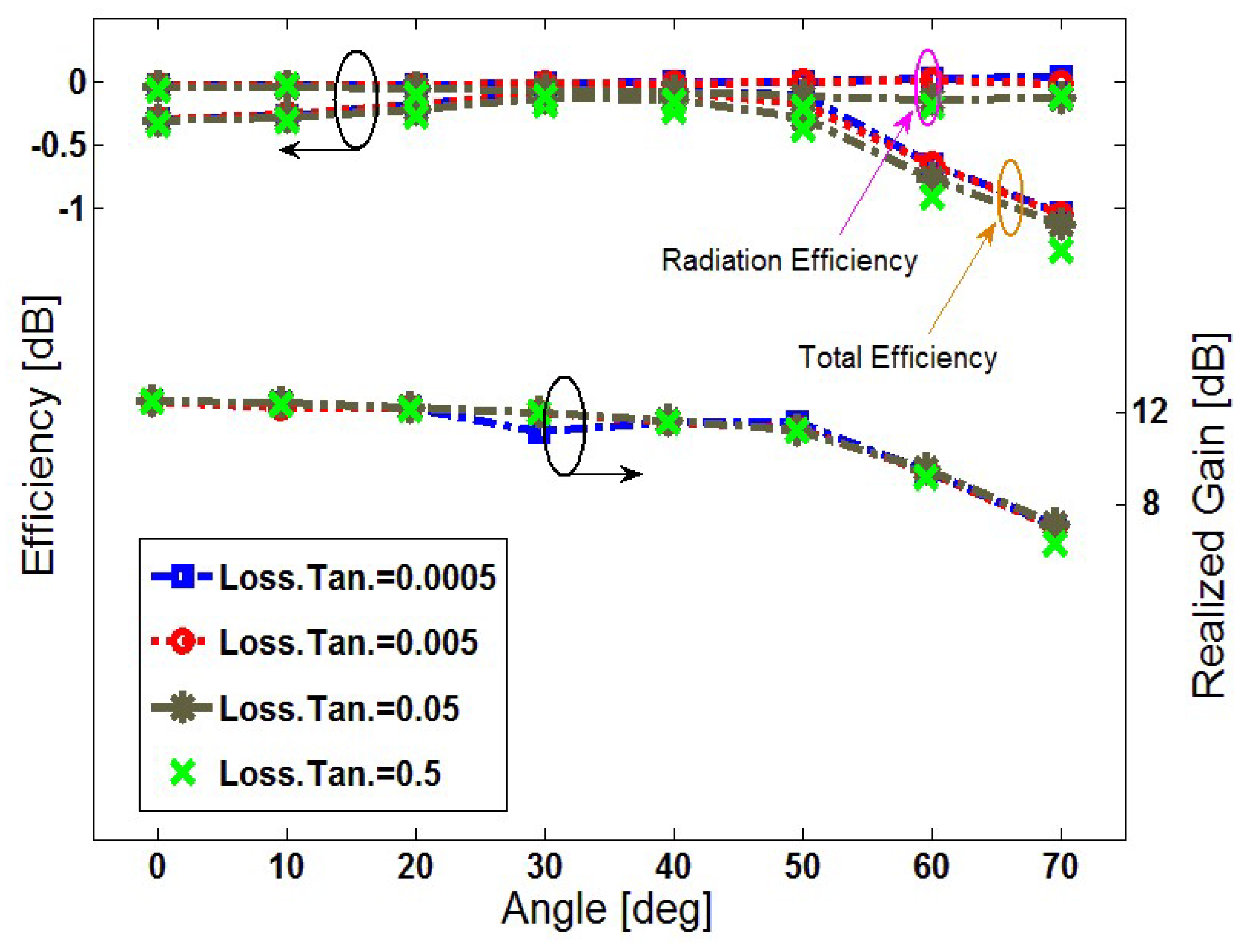
6. Insensitivity Function of the Proposed Array Design
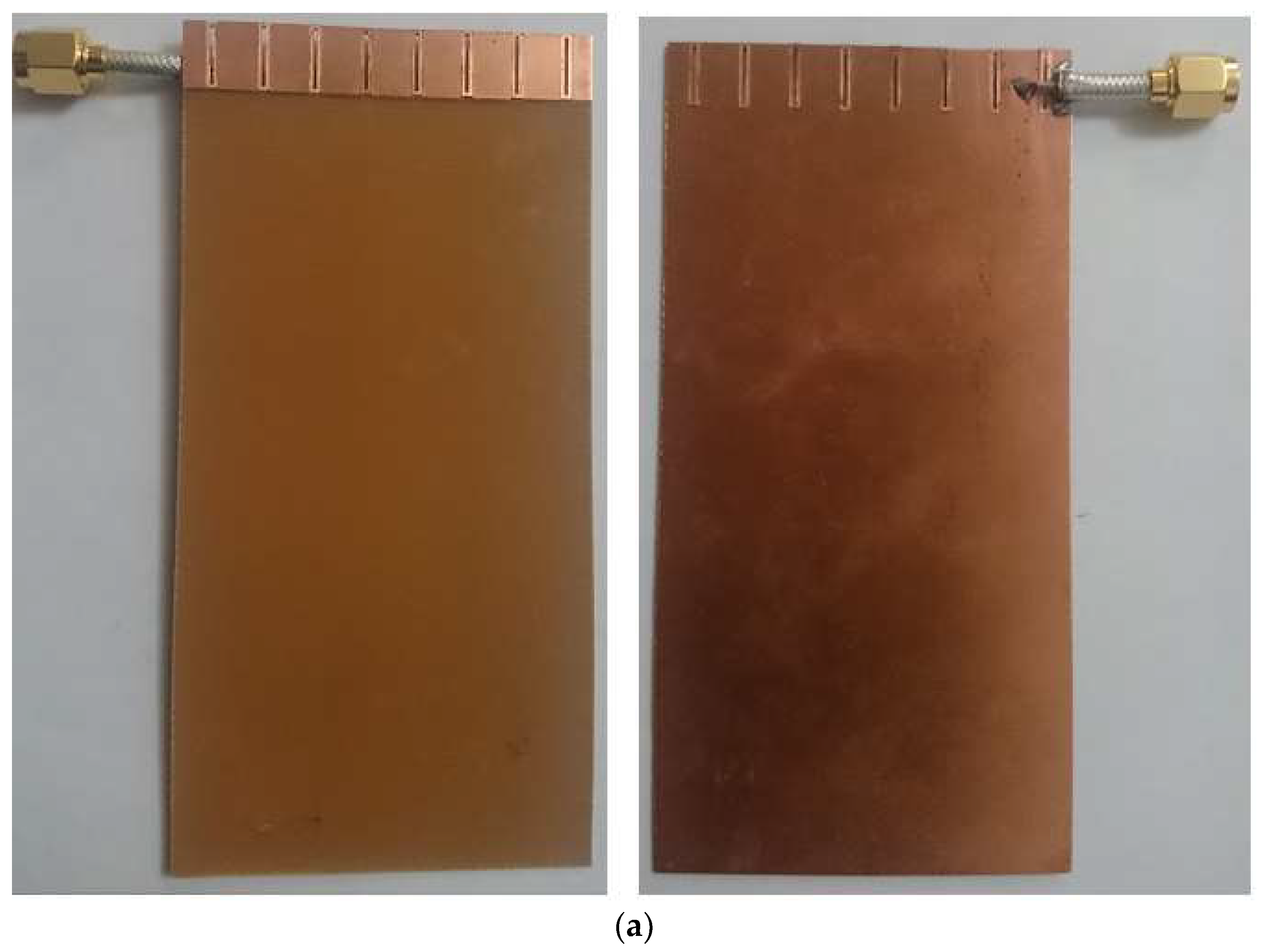
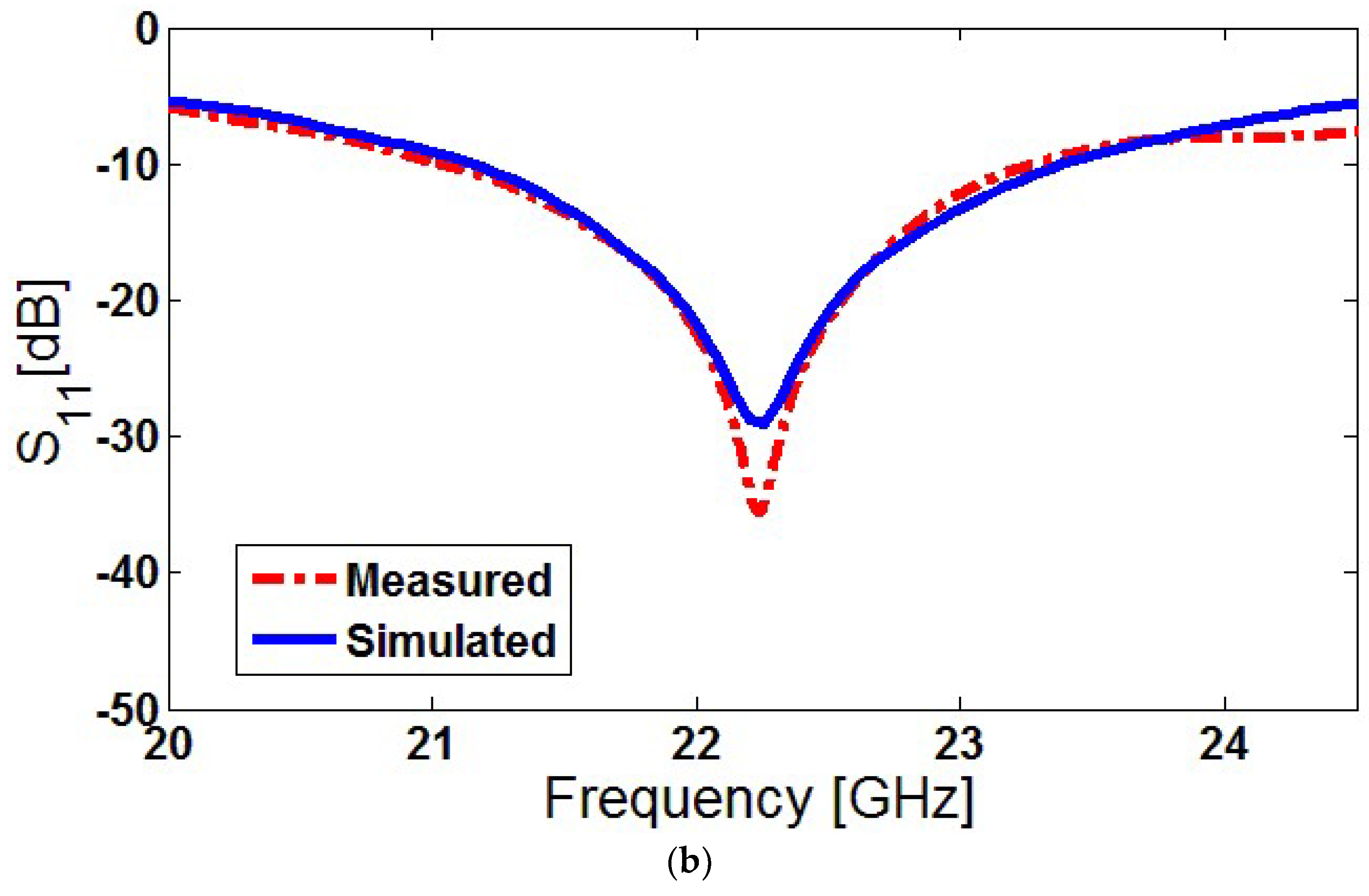
7. Fabricated Prototype and Experimental Results
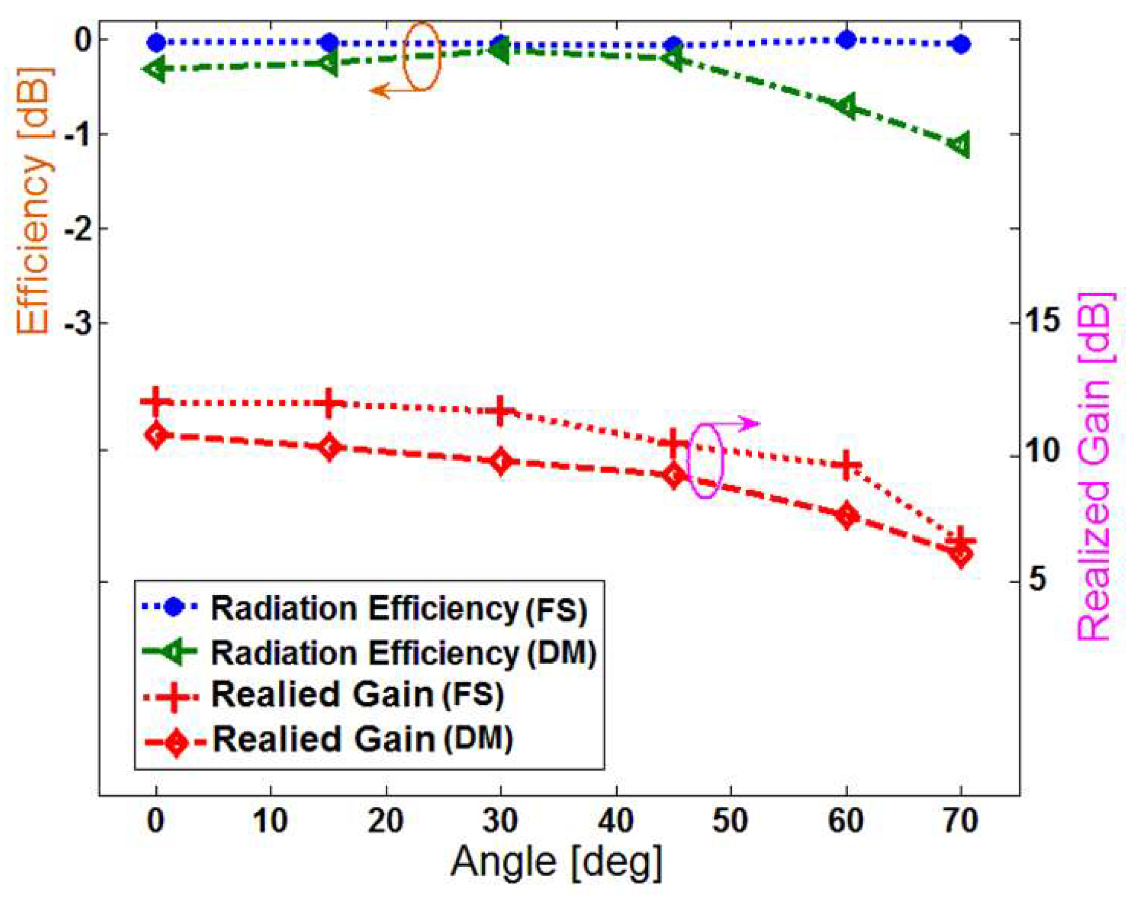
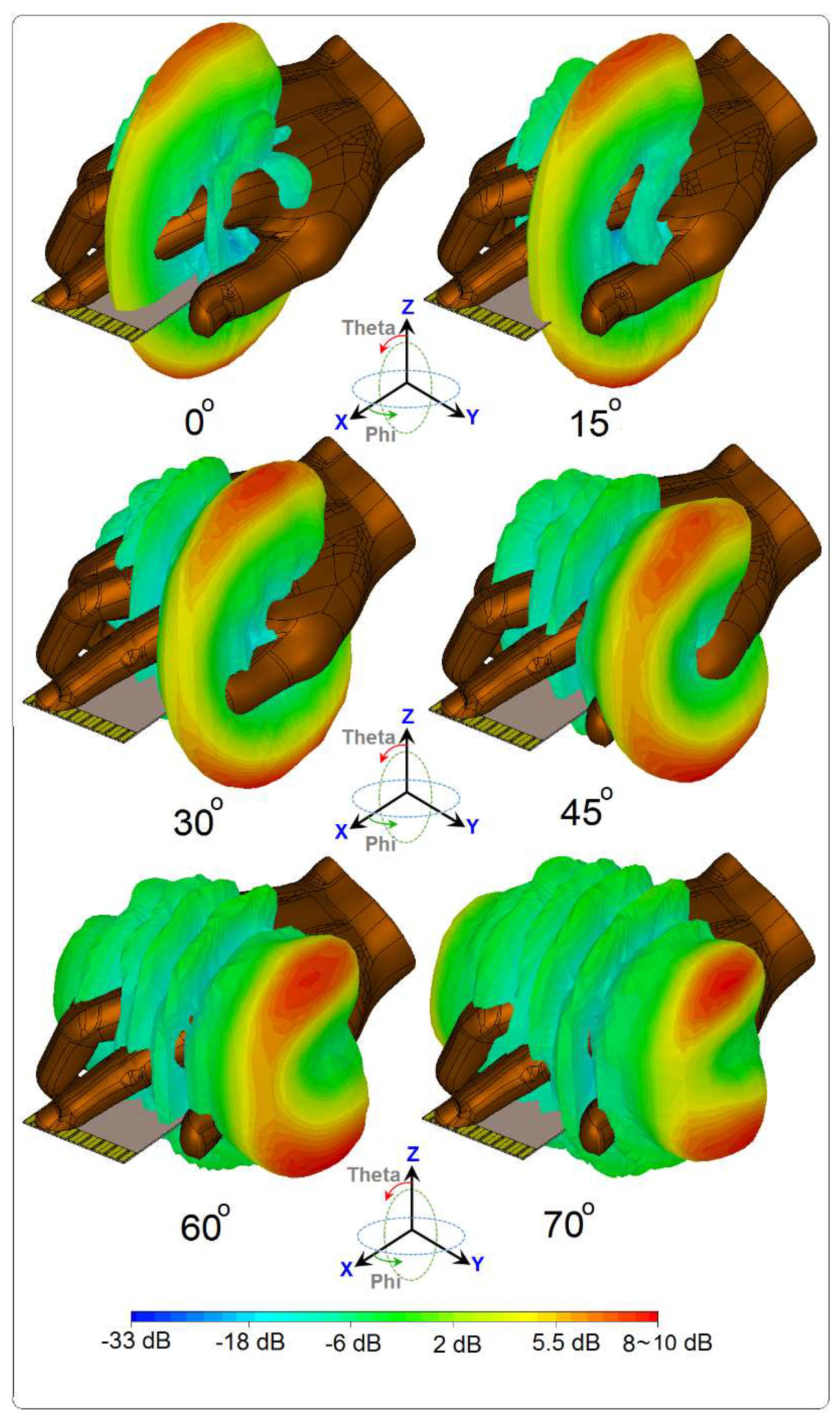
8. Effect of User Hand in Data-Mode
9. Conclusions
Author Contributions
Funding
Data Availability Statement
Conflicts of Interest
References
- Gupta, P. Evolvement of mobile generations: 1G to 5G. Int. J. Technol. Res. Eng. 2013, 1, 152–157. [Google Scholar]
- Rappaport, T.S.; Sun, S.; Mayzus, R.; Zhao, H.; Azar, Y.; Wang, K.; Wong, G.N.; Schulz, J.K.; Samimi, M.; Gutierrez, F. Millimeter wave mobile communications for 5G cellular: It will work! IEEE Access 2013, 1, 335–349. [Google Scholar] [CrossRef]
- Rappaport, T.S.; Gutierrez, F.; Ben-Dor, E.; Murdock, J.N.; Qiao, Y.; Tamir, J.I. Broadband millimeter-wave propagation measurements and models using adaptive-beam antennas for outdoor urban cellular communications. IEEE Trans. Antennas Propag. 2013, 61, 1850–1859. [Google Scholar] [CrossRef]
- Liu, D.; Pfeiffer, U.; Grzyb, J.; Gaucher, B. Advanced Millimeter-Wave Technologies; John Wiley and Sons: Hoboken, NJ, USA, 2009. [Google Scholar]
- Yarali, A. Fifth Generation (5G) Cellular Technology. In Public Safety Networks from LTE to 5G; Wiley: Hoboken, NJ, USA, 2020; pp. 171–188. [Google Scholar]
- Narayan, C.P. Antennas and Propagation; Technical Publications: Pune, Maharashtra, India, 2007. [Google Scholar]
- Roh, W.; Seol, J.-Y.; Park, J.; Lee, B.; Lee, J.; Kim, Y.; Cho, J.; Cheun, K.; Aryanfar, F. Millimeter-wave beamforming as an enabling technology for 5G cellular communications: Theoretical feasibility and prototype results. IEEE Commun. Mag. 2014, 52, 106–113. [Google Scholar] [CrossRef]
- Rajagopal, S.; Abu-Surra, S.; Pi, Z.; Khan, F. Antenna array design for multi-gbps mmwave mobile broadband communication. In Proceedings of the 2011 IEEE Global Telecommunications Conference—GLOBECOM 2011, Houston, TX, USA, 5–9 December 2011; pp. 1–6. [Google Scholar]
- Siddiqui, Z.; Sonkki, M.; Chen, J.; Berg, M.; Leinonen, M.E.; Pärssinen, A. Dual-band dual-polarized antenna for mm-wave 5G base station antenna array. In Proceedings of the 2020 14th European Conference on Antennas and Propagation (EuCAP), Copenhagen, Denmark, 15–20 March 2020; pp. 1–4. [Google Scholar]
- Parchin, N.O.; Abdalhameed, R.A. A compact Vivaldi antenna array for 5G channel sounding applications. In Proceedings of the 12th European Conference on Antennas and Propagation (EuCAP 2018), London, UK, 9–13 April 2018. [Google Scholar]
- Daigle, B. Printed circuit board material and design considerations for wireless applications. In Proceedings of the 46th Electronic Components and Technology Conference, Orlando, FL, USA, 28–31 May 1996; pp. 354–357. [Google Scholar]
- Chen, Q.; Gong, Z.; Yang, X.; Wang, Z.; Zhang, L. Design considerations for millimeter wave antennas within a chip package. In Proceedings of the IEEE International Workshop on Anti-Counterfeiting, Security and Identification, Xiamen, China, 16–18 April 2007; pp. 13–17. [Google Scholar]
- Nielsen, J.Ø.; Pedersen, G.F. Performance of Beamforming for a Handheld Device in Measured 21.5 GHz Indoor Channels. IEEE Trans. Antennas Propag. 2022, 70, 5725–5735. [Google Scholar] [CrossRef]
- Sani Yahya, M.; Rahim, S. 15 GHz grid array antenna for 5G mobile communications system. Microw. Opt. Technol. Lett. 2016, 58, 2977–2980. [Google Scholar] [CrossRef]
- Helander, J.; Zhao, K.; Ying, Z.; Sjöberg, D. Performance Analysis of Millimeter-Wave Phased Array Antennas in Cellular Handsets. IEEE Antennas Wirel. Propag. Lett. 2016, 15, 504–507. [Google Scholar] [CrossRef]
- Sun, W.; Li, Y.; Chang, L.; Li, H.; Qin, X.; Wang, H. Dual-band dualpolarized microstrip antenna array using double-layer gridded patches for 5G millimeter-wave applications. IEEE Trans. Antennas Propag. 2021, 69, 6489–6499. [Google Scholar] [CrossRef]
- Seo, J.; Yoon, I.; Jung, J.; Ryoo, J.; Park, J.; Lee, W.; Ko, D.; Oh, J. Miniaturized dual-band broadside/endfire antenna-in-package for 5G smartphone. IEEE Trans. Antennas Propag. 2021, 69, 8100–8114. [Google Scholar] [CrossRef]
- Ojaroudi, N.; Ghadimi, N. UWB small slot antenna with WLAN frequency band-stop function. Electron. Lett. 2013, 49, 1317–1318. [Google Scholar] [CrossRef]
- Sethi, W.T.; Vettikalladi, H.; Minhas, B.K.; Alkanhal, M.A. High gain and wide-band aperture-coupled microstrip patch antenna with mounted horn integrated on FR4 for 60 GHz communication systems. In Proceedings of the IEEE Symposium on Wireless Technology and Applications (ISWTA), Kuching, Malaysia, 22–25 September 2013; pp. 359–362. [Google Scholar]
- Hong, W.; Baek, K.; Lee, Y.; Kim, Y.G. Design and analysis of a low-profile 28 GHz beam steering antenna solution for future 5G cellular applications. In Proceedings of the IEEE International Microwave Symposium, Tampa, FL, USA, 1–6 June 2014. [Google Scholar]
- Salman, J.W.; Ameen, M.M.; Hassan, S.O. Effects of the loss tangent, dielectric substrate permittivity and thickness on the performance of circular microstrip antennas. J. Eng. Dev. 2006, 10, 1–13. [Google Scholar]
- Salokhe, B.T.; Mali, S.N. Effect of substrate material variations on RMSA, CMSA and NLMSA. Int. J. Adv. Res. Electr. Electron. Instrum. Eng. 2014, 3, 14009–14015. [Google Scholar]
- CST Microwave Studio, Version 2020; CST: Framingham, MA, USA, 2020.
- Amitay, N.; Galindo, V.; Wu, C.P. Theory and Analysis of Phased Array Antennas; Wiley-Interscience: New York, NY, USA, 1972. [Google Scholar]
- Xu, R.; Chen, Z.N. A Compact Beamsteering Metasurface Lens Array Antenna with Low-Cost Phased Array. IEEE Trans. Antennas Propag. 2021, 69, 1992–2002. [Google Scholar] [CrossRef]
- Guo, J.; Xiao, S.; Liao, S. A Low-Cost Feeding Network with Simple Phase Shift Structures. In Proceedings of the 2018 IEEE International Conference on Computational Electromagnetics (ICCEM), Chengdu, China, 26–28 March 2018; pp. 1–3. [Google Scholar]
- Roshani, S.; Koziel, S.; Roshani, S.; Jamshidi, M.B.; Parandin, F.; Szczepanski, S. Design of a Patch Power Divider with Simple Structure and Ultra-Broadband Harmonics Suppression. IEEE Access 2021, 9, 165734–165744. [Google Scholar] [CrossRef]
- Parchin, N.O. Dual-Band Phased Array 5G Mobile-Phone Antenna with Switchable and Hemispherical Beam Pattern Coverage for MIMO-Diversity Communications. ACES J. 2022, 36, 1602–1609. [Google Scholar] [CrossRef]
- Nakano, H.; Yamauchi, J. Printed slot and wire antennas: A Review. Proc. IEEE 2012, 100, 2158–2168. [Google Scholar] [CrossRef]
- Kim, D.-Y.; Lim, Y.; Yoon, H.-S.; Nam, S. High-Efficiency W-Band Electroforming Slot Array Antenna. IEEE Trans. Antennas Propag. 2015, 63, 1854–1857. [Google Scholar] [CrossRef]
- Ojaroudi, N. Application of protruded strip resonators to design an UWB slot antenna with WLAN band-notched characteristic. Prog. Electromagn. Res. C 2014, 47, 111–117. [Google Scholar] [CrossRef]
- Hong, W.; Ko, S.-T.; Lee, Y.; Baek, K.-H. Compact 28 GHz antenna array with full polarization flexibility under yaw, pitch, roll motions. In Proceedings of the 2015 9th European Conference on Antennas and Propagation (EuCAP), Lisbon, Portugal, 13–17 April 2015; pp. 1–3. [Google Scholar]
- Available online: https://www.lasercalculator.com/db-percent-converter/ (accessed on 14 September 2022).
- Hong, W.; Baek, K.-H.; Ko, S. Millimeter-wave 5G antennas for smartphones: Overview and experimental demonstration. IEEE Trans. Antennas Propag. 2017, 65, 6250–6261. [Google Scholar] [CrossRef]
- Ide, T.; Kanaya, H. 28 GHz one-sided directional slot array antenna for 5G application. In Proceedings of the 2019 IEEE 21st Electronics Packaging Technology Conference (EPTC), Singapore, 4–6 December 2019; pp. 440–443. [Google Scholar]
- Chen, C.-N.; Lin, Y.-H.; Hung, L.-C.; Tang, T.-C.; Chao, W.-P.; Chen, C.-Y.; Chuang, P.-H.; Lin, G.-Y.; Liao, W.-J.; Nien, Y.H. 38-GHz Phased Array Transmitter and Receiver Based on Scalable Phased Array Modules with Endfire Antenna Arrays for 5G MMW Data Links. IEEE Trans. Microw. Theory Tech. 2021, 69, 980–999. [Google Scholar] [CrossRef]
- Ojaroudiparchin, N.; Shen, M.; Pedersen, G.F. Beam-steerable microstrip-fed bow-tie antenna array for fifth generation cellular communications. In Proceedings of the 2016 10th European Conference on Antennas and Propagation (EuCAP), Davos, Switzerland, 10–15 April 2016. [Google Scholar]
- Zhang, J.; Zhang, S.; Li, Y.; Pedersen, G.F. Printed vertically- polarized quasi-endfire beam steering array with full ground plane for 5g mobile applications. In Proceedings of the 13th European Conference on Antennas and Propagation (EuCAP), Krakow, Poland, 31 March–5 April 2019. [Google Scholar]
- Ojaroudiparchin, N.; Shen, M.; Zhang, S.; Pedersen, G.F. A switchable 3-D-coverage-phased array antenna package for 5G mobile terminals. IEEE Antennas Wirel. Propag. Lett. 2016, 15, 1747–1750. [Google Scholar] [CrossRef]
- Zhang, J.; Zhang, S.; Lin, X.; Fan, Y.; Pedersen, G. 3D radiation pattern reconfigurable phased array for transmission angle sensing in 5G mobile communication. Sensors 2018, 18, 4204. [Google Scholar] [CrossRef] [PubMed]
- Parchin, N.O.; Shen, M.; Pedersen, G.F. Small-size tapered slot antenna (TSA) design for use in 5G phased array applications. Appl. Comput. Electromagn. Soc. (ACES) J. 2017, 3, 1054–4887. [Google Scholar]
- Zhao, A.; Ai, F. 5G mm-wave antenna array based on T-slot antenna for mobile terminals. In Proceedings of the 2018 IEEE Asia-Pacific Conference on Antennas and Propagation (APCAP), Auckland, New Zealand, 5–8 August 2018. [Google Scholar]
- Ojaroudi Parchin, N.; Al-Yasir, Y.; Abdulkhaleq, A.M.; Elfergani, I.; Rayit, A.; Noras, J.M.; Rodriguez, J.; Abd-Alhameed, R.A. Frequency reconfigurable antenna array for mm-Wave 5G mobile handsets. In Proceedings of the 9th International Conference on Broadband Communications, Networks, and Systems, Faro, Portugal, 19–20 September 2018. [Google Scholar]
- Tatomirescu, A.; Oprian, A.; Zhekov, S.; Pedersen, G.F. Beam-steering array for handheld devices targeting 5G. In Proceedings of the 2015 International Symposium on Antennas and Propagation (ISAP), Hobart, TAS, Australia, 9–12 November 2015. [Google Scholar]
- Park, E.; Yoon, Y.J.; Kim, H. Dual Polarization L-Shaped Slot Array Antenna for 5G Metal-Rimmed Mobile Phone. In Proceedings of the 2018 International Symposium on Antennas and Propagation (ISAP), Busan, Korea, 23–26 October 2018; pp. 1–2. [Google Scholar]
- Rafique, U.; Dalal, P.; Abbas, S.M.; Khan, S. Phased Array Antenna for Millimeter-Wave 5G Mobile Phone Applications. In Proceedings of the 2022 IEEE Wireless Antenna and Microwave Symposium (WAMS), Rourkela, India, 5–8 June 2022; pp. 1–4. [Google Scholar] [CrossRef]
- di Paola, C.; Zhao, K.; Zhang, S.; Pedersen, G.F. Hybrid Switchable Phased Array with p-i-n Diodes for 5G Mobile Terminals. In Proceedings of the 2021 15th European Conference on Antennas and Propagation (EuCAP), Dusseldorf, Germany, 22–26 March 2021; pp. 1–5. [Google Scholar] [CrossRef]
- Parchin, N.O.; Zhang, J.; Abd-Alhameed, R.A.; Pedersen, G.F.; Zhang, S. A planar dual-polarized phased array with broad bandwidth and quasi-endfire radiation for 5G mobile handsets. IEEE Trans. Antennas Propag. 2021, 69, 6410–6419. [Google Scholar] [CrossRef]
- Ilvonen, J.; Kivekas, O.; Holopainen, J.; Valkonen, R.; Rasilainen, K.; Vainikainen, P. Mobile terminal antenna performance with the user’s hand. IEEE Antenna Wirel. Propag. Lett. 2011, 10, 772–775. [Google Scholar] [CrossRef]
- Alshamaileh, M.H.; Alja’afreh, S.S.; Almajali, E. Nona-band, hybrid antenna for metal-rimmed smartphone applications. IET Microw. Antennas Propag. 2019, 13, 2439–2448. [Google Scholar] [CrossRef]


| Parameter | Wsub | Lsub | hsub | W | W1 |
|---|---|---|---|---|---|
| Value (mm) | 55 | 110 | 0.787 | 5.25 | 1.5 |
| Parameter | W2 | W3 | W4 | L | L1 |
| Value (mm) | 0.5 | 3.125 | 3.125 | 8.3 | 7.8 |
| Reference | Bandwidth (GHz) | Efficiency (%) | Gain (dB) | Isolation (dB) | Scanning Range | Insensitivity Function |
|---|---|---|---|---|---|---|
| [37] | 21–22 | - | 8–12 | 14 | 0°~75° | No |
| [38] | 27.5–28.5 | 70 | 7–11 | 11 | 0°~60° | No |
| [39] | 21–23 | 85 | 9–11.5 | 12 | 0°~60° | No |
| [40] | 27.4–28.8 | - | 7–11 | 16 | 0°~60° | No |
| [41] | 27–29 | 80 | 5–9.5 | 13 | 0°~75° | No |
| [42] | 27.5–28.5 | - | 8–11.5 | 15 | 0°~60° | No |
| [43] | 27.75–28.25 | - | 10–13 | 20 | 0°~50° | No |
| [44] | 25–29 | 75–90 | 8–11 | 15 | 0°~75° | No |
| [45] | 27.5–29.5 | - | 6–8 | 20 | 0°~30° | No |
| Proposed | 21–23.5 | 80–95 | 10–12.5 | 17 | 0°~75° | YES |
Publisher’s Note: MDPI stays neutral with regard to jurisdictional claims in published maps and institutional affiliations. |
© 2022 by the authors. Licensee MDPI, Basel, Switzerland. This article is an open access article distributed under the terms and conditions of the Creative Commons Attribution (CC BY) license (https://creativecommons.org/licenses/by/4.0/).
Share and Cite
Ullah, A.; Ojaroudi Parchin, N.; Amar, A.S.I.; Abd-Alhameed, R.A. Eight-Element Antenna Array with Improved Radiation Performances for 5G Hand-Portable Devices. Electronics 2022, 11, 2962. https://doi.org/10.3390/electronics11182962
Ullah A, Ojaroudi Parchin N, Amar ASI, Abd-Alhameed RA. Eight-Element Antenna Array with Improved Radiation Performances for 5G Hand-Portable Devices. Electronics. 2022; 11(18):2962. https://doi.org/10.3390/electronics11182962
Chicago/Turabian StyleUllah, Atta, Naser Ojaroudi Parchin, Ahmed S. I. Amar, and Raed A. Abd-Alhameed. 2022. "Eight-Element Antenna Array with Improved Radiation Performances for 5G Hand-Portable Devices" Electronics 11, no. 18: 2962. https://doi.org/10.3390/electronics11182962
APA StyleUllah, A., Ojaroudi Parchin, N., Amar, A. S. I., & Abd-Alhameed, R. A. (2022). Eight-Element Antenna Array with Improved Radiation Performances for 5G Hand-Portable Devices. Electronics, 11(18), 2962. https://doi.org/10.3390/electronics11182962