Article

Design of a Flat-Panel Metasurface Reflectarray C-Band Antenna

1
Department of Electronics Engineering, Pusan National University, Busan 26241, Korea
2
Defense Space Technology Center, Agency for Defense Development, Daejeon 34186, Korea
*
Author to whom correspondence should be addressed.
Electronics 2022, 11(17), 2729; https://doi.org/10.3390/electronics11172729
Submission received: 18 July 2022 / Revised: 6 August 2022 / Accepted: 10 August 2022 / Published: 30 August 2022
(This article belongs to the Special Issue Antenna Designs for 5G/IoT and Space Applications, Volume II)

Abstract

:
This paper presents the design of a flat-panel metasurface reflectarray antenna fed by a circular horn antenna for satellite applications. A metasurface-based reflectarray antenna is similar to a flat-panel reflector and is characterized by a reflection angle adjustment that is free from the well-known Snell’s law. This was done by compensating the angle of the incident wave using the structure of each unit cell. A unit cell of the designed metasurface is composed of a dual-ring resonator. Many satellites use a reflectarray antenna due to its flat-panel structure and the capability of steering the reflection angle of the incident wave. This paper presents the detailed design procedure using a commercial 3D EM simulator and the operation principle of the flat-panel metasurface reflectarray antenna, including the simulation setup, design environment and automation. The proposed design method is scalable to any EM solvers for numerical analysis. A reflectarray composed of a 16 × 16-unit cell array at 5.8 GHz (C-band) was designed and validated by measurement as a proof of concept. It is excited by a low-cost linearly polarized circular horn cantenna. The measured antenna gain and radiation patterns show good agreement with the simulation. The measured antenna gain of the reflectarray was 22.4 dBi (cross-pol suppression level: 36 dB), and the reflection angle was 15° at normal incidence.

1. Introduction

The concept of a reflectarray was proposed in the 1960s using a short-circuited waveguide array composed of different lengths [1]. Early reflectarray designs have not received much attention due to their impractical structures, but the development of a printed flat-panel microstrip reflectarray paved a new way in the late 1980s [2]. The breakthrough of printed microstrip circuit technology has contributed significantly to the innovation of reflectarray antennas, which have emerged as high-gain antennas for long-distance communications, such as nano-/cube-satellite communications.
Dish-type parabolic reflector antennas are widely used in satellite communications for the space-Earth link because of their high-gain property. Small satellite platforms such as CubeSat have extremely limited payload, so it is challenging to mount bulky high-gain reflector antennas on them for the space-Earth link [3]. The advance of resonator-based metamaterial technology has expedited the progress of the metamaterial-based antennas. The metasurface consisting of resonator arrays is widely adopted for antenna, absorber, power-splitter and reflector designs [4,5,6,7,8]. It is because the negative constitutive parameters at desired frequency can be easily obtained by utilizing the planar resonator array structures. For the high gain antenna applications, a flat-panel metasurface reflectarray antenna is a good candidate for the high-gain foldable antenna of CubeSats because of their flat reflectors fabricated from a multi-layer PCB [9,10,11].
The operation principle and structure of a reflectarray are similar to those of a parabolic reflector antenna [12,13,14]. Both antennas reflect an incident wave from a source feeding antenna to focus or steer the wave’s direction. The direction of the reflected wave is determined by the shape or phase response of the reflector. A conventional parabolic reflector antenna has a bulky curved metallic surface as a reflector, whereas a reflectarray has a flat planar antenna or resonator array, which results in a low profile, low mass, ease of fabrication and low cost.
Reflectarrays are also different from conventional phased antenna arrays because they do not have a beamforming/steering network, such as a power dividing circuit and phase shifters. The phase response of each unit cell of a reflectarray works as a phase shifter, which results in high reliability due to the relatively simple feeding and passive phase shifting property. Unlike traditional active phased antenna arrays, designing large arrays of thousands of elements is much easier.
This paper discusses a generalized design procedure for a planar reflectarray antenna design and presents a high-gain reflectarray in the C-band as a design example. It shows detailed simulation setup, design environment and automation of a reflectarray antenna. The detailed design procedure of a unit-cell and array analysis using a commercially available full-wave EM solver are discussed. The presented design procedure is demonstrated by a flat-panel reflectarray antenna consisting of a dual-ring resonator fed by a circular horn antenna. Measured experimental data agree well with the proposed design and analysis. It should be noted that the proposed design method is scalable to any EM solvers for numerical analysis.
The measured antenna has a high co-pol gain value of 20.0–22.2 dBi with a cross-pol suppression level of 26–39 dB at the operation frequency. There was an error of 1–2° for the beam steering direction between the simulated data and the measured data. The size of the designed 16 × 16 reflectarray is 400 × 400 mm2, whereas the distance between the source horn antenna and the reflectarray is 200 mm. The proposed design procedure is scalable to any frequency band.
This article is organized as follows. Section 2 presents the detailed operation principle of the reflectarray antenna, its geometry, antenna design parameters and dimensions. Pictures of planar, folded and inactive modes of the antenna are also included in this section.
The measured antenna performance parameters in the C-band, such as the antenna gain, |S11|, polarization, source horn antenna are presented in Section 3. The conclusion is given in Section 4.

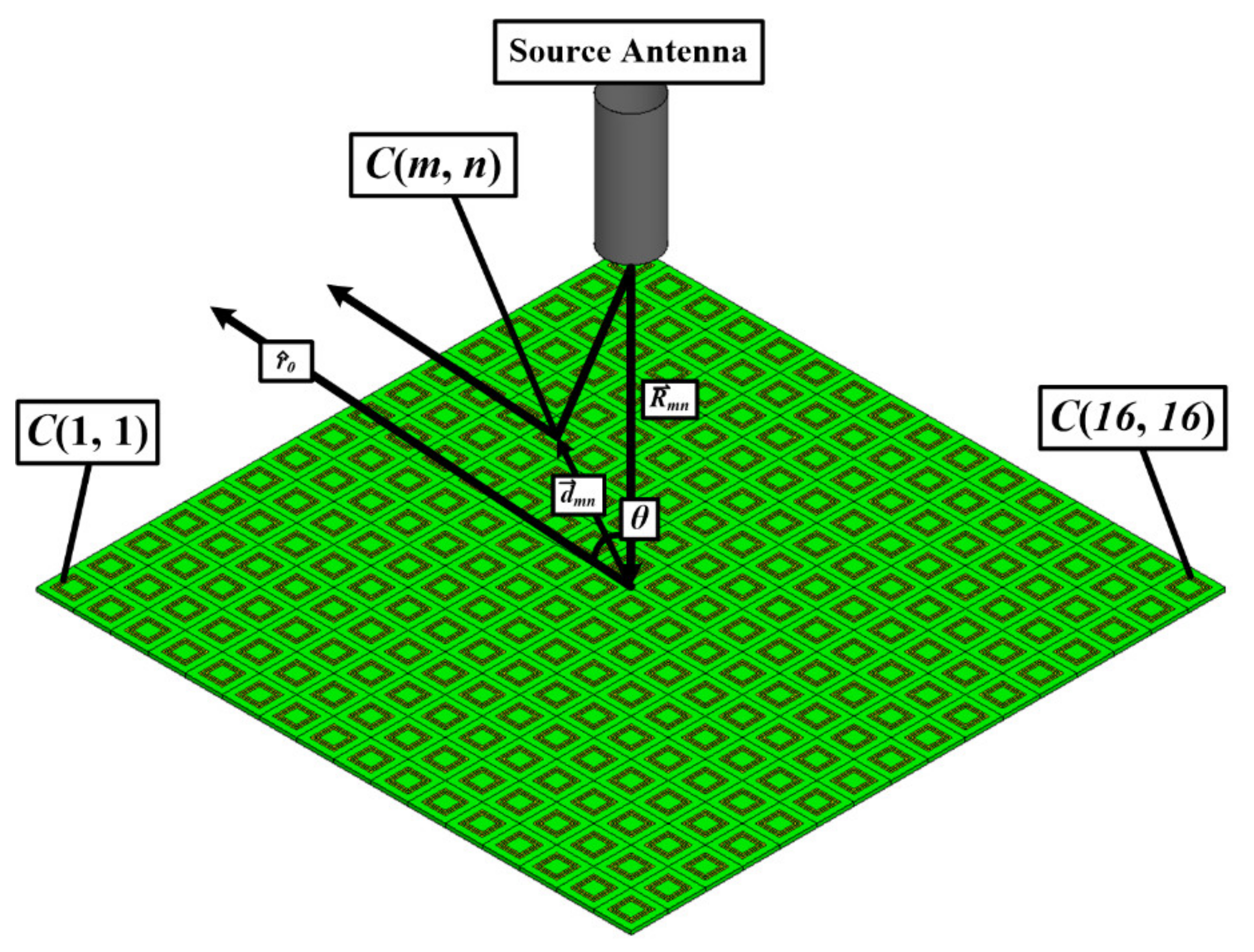
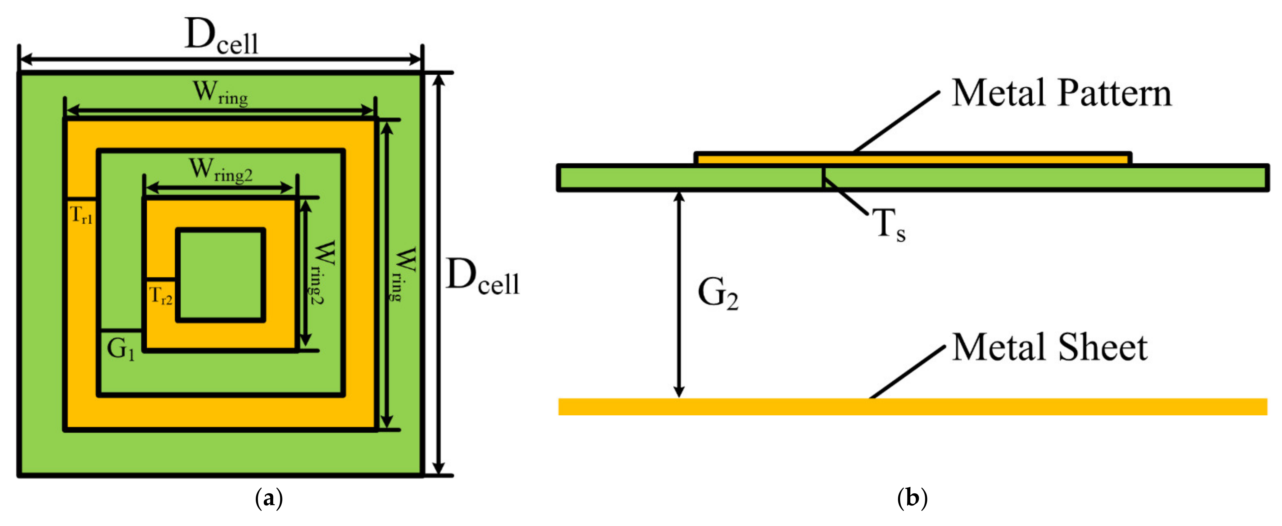
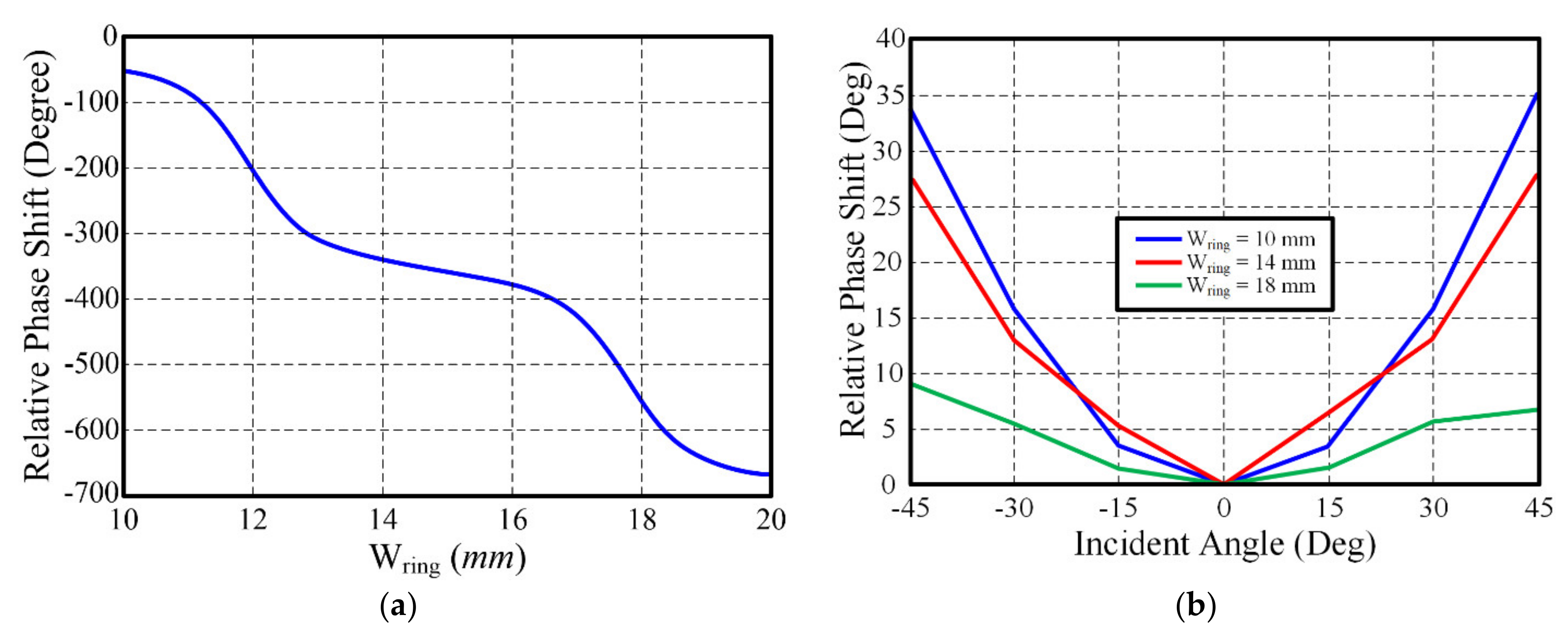
2. Operation Principle of the Reflectarray Antenna

The operation principle of a flat-panel metasurface reflectarray is shown in Figure 1.
The incident electromagnetic waves radiated from a source antenna are reflected by the flat-panel metasurface. The metasurface consists of an array of unit cells, each of which shifts the phase of the incident waves in order to propagate them in the desired direction. The array factor AF(θ, ϕ) of a flat-panel metasurface reflector array with M × N unit-cells can be written as (1) and (2) when the metasurface reflector is located on the xy-plane [15]:
AF θ , ϕ = m = 0 M 1 n = 0 N 1 A m n e j k 0 m d x u + m d y v
u = sin θ cos ϕ + β x v = sin θ sin ϕ + β y
where Amn is the complex excitation of the (m, n)-th unit cell, C(m, n) and k0 is the free space wavenumber. β x and β y are the progressive phase shift between the adjacent unit-cells in the x and y directions, respectively. The progressive phase shifts can be expressed as (3) in order to create reflected waves focused in the (θr, ϕr) direction. dx and dy are the period of the unit cell in the x and y directions, respectively.
β x = sin θ 0 cos ϕ 0 β y = sin θ 0 sin ϕ 0
The phase shift (Δϕmn) on the mn-th unit cell, C(m, n), can be calculated by using the period of unit cell, β x , and β y . It is critical to compensate the phase of the incident waves using the unit-cell structure to control the reflection angle. The phase of the reflected wave at C(m, n) can be calculated by adding the phase of the incident wave to the relative phase shift due to the unit cell. The required phase shift distribution Δϕ to obtain a desired reflection angle can be analytically calculated by (4):
Δ ϕ m n = 2 N π + k 0 R m n d m n · r ^ 0   N = 0 , 1 , 2 ,
where R m n is the position vector from the source antenna to C(m, n), d m n is the position vector from the center of the metasurface reflector to C(m, n), k0 is the wavenumber and r 0 is the unit vector in the direction of the reflected waves.
The unit cell of the flat-panel reflectarray, which operates at 5.8 GHz (C-band), is composed of dual square rings, as shown in Figure 2. The dual square rings are printed on a widely used commercially available 0.8-mm-thick (Ts) FR4 substrate (εr = 4.4 and tan δ = 0.04). The unit cell is placed above a solid metal GND plane, as shown in Figure 2. The width and length (Wring) of the outer ring vary from 6 to 16 mm, whereas the unit cell size (Dcell) is fixed at 25 mm. The widths of the inner and outer rings (Tr1, Tr2) and the gap between the rings (G1) are also fixed to 1 mm for design simplicity. The metal thickness and the air gap (G2) between the GND plane and the dual square ring are 18 μm and 2.76 mm, respectively. All the detailed unit cell dimensions are summarized in Table 1.
The phase of the reflected wave changes as the size of the double square ring changes because the impedance of the unit cell is a function of the length and width of the square ring [16,17]. To analyze the phase response of the unit cell according to the size of the dual square rings, an infinite array condition was assumed, and calculation was done by a commercial 3D full-wave simulator, Ansys HFSS. The master-slave boundary condition and Floquet port setup were applied to build an infinite unit cell array simulation environment. The phase response depending on the size of the double ring and incident angle at 5.8 GHz is shown in Figure 3 It is clear that the relative phase shift strongly depends on the size of the ring resonator. The relative phase shift according to the incident angle is very small when the angle of incidence is less than +/−15°. The incidence/reflection angle of +/−15° is wide enough for the LEO satellite applications because of the mission altitude of the LEO satellites. The mission altitude of the LEO satellite is typically 2000 km or less. It can cover a circular area with a diameter of 709 km. It is wide enough to cover a small country of a city.
In this parametric analysis, the size of the unit cell (Dcell) was fixed at 25 mm, the length of the outer ring (Wring) was varied from 10 to 20 mm and the width (Tr1, Tr2, G1) and gap between the square rings were fixed. The observed relative phase shifts in the unit cell ranged from −50° to −670° at 5.8 GHz. The obtained phase shifting range of 620° is wide enough to compensate the incident waves because only a phase shifting range of 360° is required to set any reflection angle. The proper dimension of the dual square ring resonator (Wring) is 10–16 mm because it covers phase shifts of 0–360° at the operation frequency of 5.8 GHz. A 16 × 16-unit cell array was designed based on the phase response of the unit cell shown in Figure 2 and Equation (4).
The source horn antenna is aligned to the center of the flat panel metasurface, and the distance between the source antenna and the metasurface is 200 mm. The size of the dual square ring can be determined by calculating the required phase to compensate the incident wave on the metasurface according to (4). The size of the dual square rings and their associated phase shifting value were tabulated, and the 16 × 16-unit cell array was placed automatically by utilizing custom-built Python code for Ansys HFSS. The design procedure is shown in Figure 4a.
A simulation was run in Ansys HFSS electromagnetic simulator to verify the performance of the designed metasurface reflectarray antenna. To save computation resources and simulation time, the finite-element and the boundary integral (FE-BI) domain decomposition method was applied in this work, as shown in Figure 4b [18,19,20,21]. The integration boundaries were set up around the source horn and the designed flat-panel reflectarray. The field information near the source horn antenna was integrated and applied to the reflectarray to calculate the reflected waves. The simulation result of the reflected wave is shown in Figure 4c. The designed reflection angle (θr) of 15° is clearly observed.

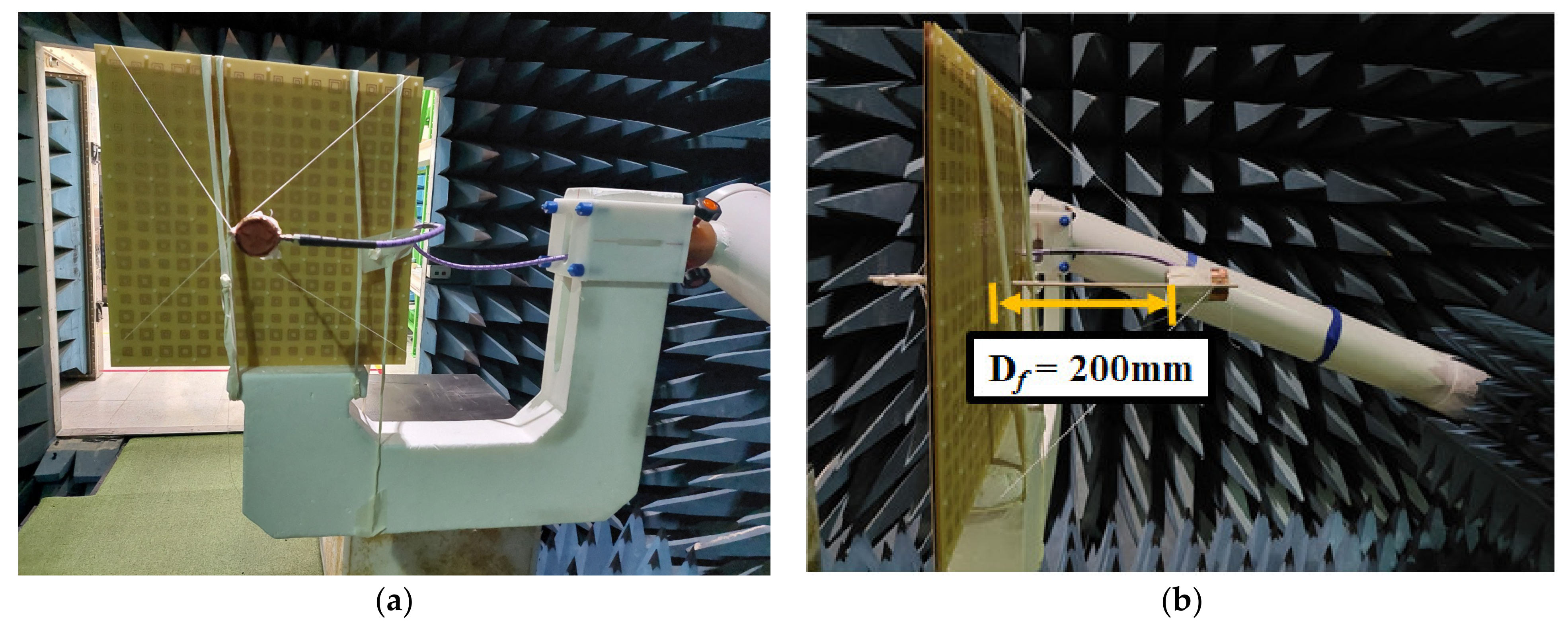
3. Reflectarray Antenna Measurement

3.1. Source Antenna: Circular Waveguide Antenna

A cylindrical horn antenna was designed for the feeding antenna based on dominant mode analysis [22]. The size of the cylindrical can is 35 × 88 mm2 (diameter × height), and it has a single dominant TM11 mode in the band of 5.0~6.6 GHz, which is broad enough to cover the whole operation frequency of the proposed metasurface reflector. The length of a feeding probe is 12 mm, and the distance between the probe and the metal wall is 20 mm. The fabricated source horn antenna and its measurement data are shown in Figure 5.
All antenna parameters were measured in an anechoic chamber. The designed antenna has a broad impedance bandwidth of 5.8–6.0 GHz (Figure 6a) and high antenna gain value of 6.8~7.8 dBi (Figure 6b). The measured cross-pol suppression level was higher than 20 dB at the operation frequency band. All the simulation results show good agreement with the measurement data.

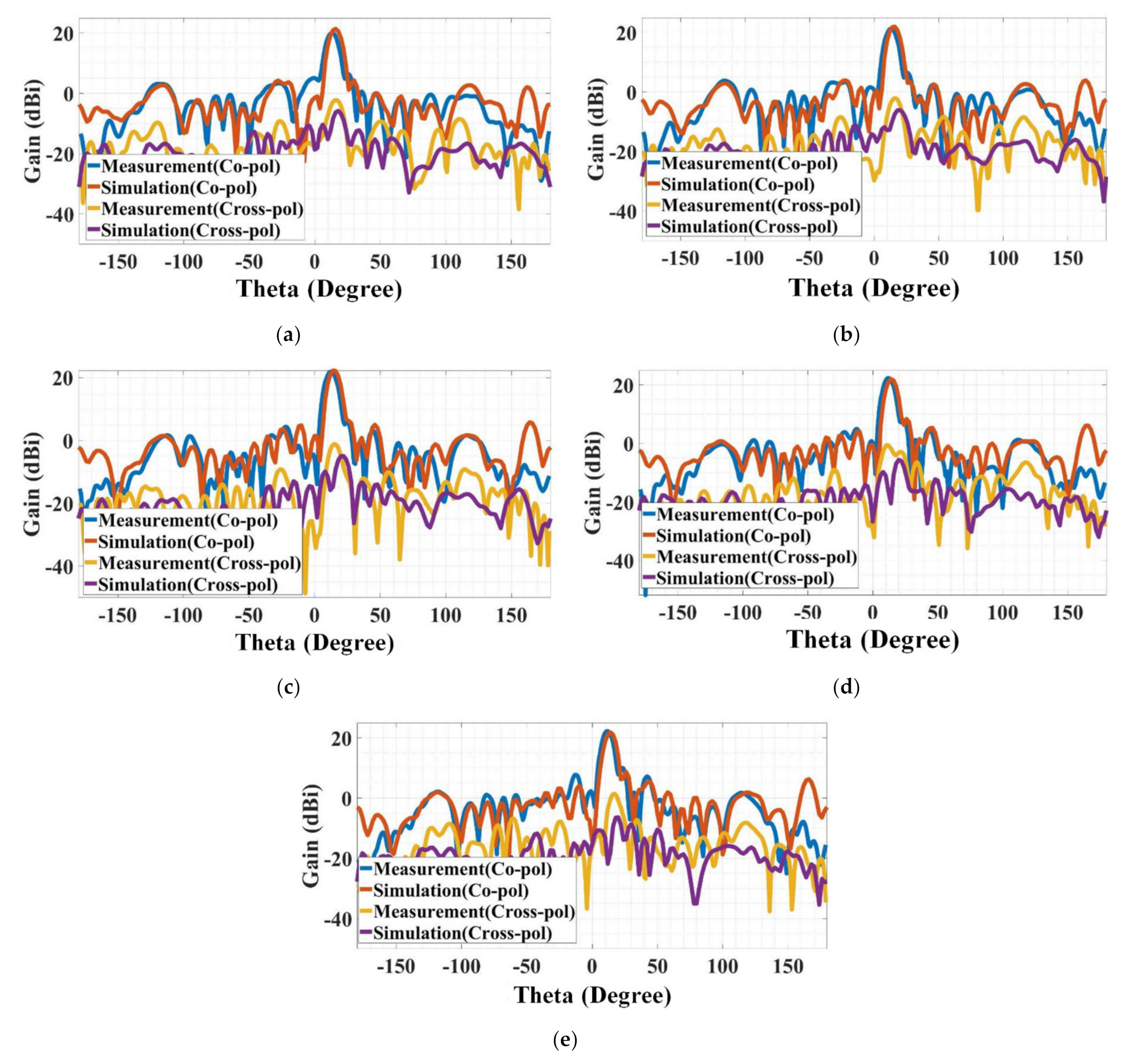
3.2. Flat-Panel Metasurface Reflectarray Antenna

The designed flat panel reflectarray antenna was printed on an FR4 PCB board. The air gap between the dual square ring metasurface and the GND plane was maintained by cylindrical PCB spacers made of polyester. The source horn antenna was tied to a wooden pole to keep a distance of 200 mm from the metasurface reflector, as shown in Figure 5 (F/D = 0.35). The far-field response of the fabricated flat panel metasurface reflectarray antenna was measured in an anechoic chamber. The measured far-field co-pol and cross-pole gain patterns are shown in Figure 7. The results show good agreement between the measurement and simulation. The measured peak co-pol gain value was 20~22.2 dBi, the cross-pol gain value was −3.6~−0.6 dBi, and the side-lobe level was 16~18 dB. There was less than 1 dB of difference between the simulated and measured co-pol peak gain values. The measured radiation directions of the reflected waves were 12~14°, which were very close to the designed radiation direction of 14~16°. The small discrepancy of 1–3° in the reflection angle can be considered as fabrication error such as misalignment of the mounted source horn antenna. The measured 1-dB and 3-dB beamwidth values are 5° and 10°, respectively. Figure 7 shows 1-dB and 3-dB bandwidth of the proposed reflectarray antenna. The 1-dB and 3-dB bandwidth are 500 MHz (5.6~6.1 GHz, 8.5 %) and 860 MHz (5.4~6.26 GHz, 14.8%), respectively. The aperture efficiency (εA) can be calculated from the measurement data because ε A = A e / A p = λ 0 2 G / 4 π A p where Ae is effective area of antenna, Ap is physical area of antenna, λ0 is a wavelength and G is antenna gain [14]. The measured aperture efficiency of the proposed antenna is 21.1%. The performance comparison table is shown in Table 2 and Table 3. Those reported reflectarray antennas at the C-band have multi band or tunable capability, but they also have relatively high loss due to active components, such as varactors or PIN diodes. The proposed reflectantenna features high gain and a low-profile.

4. Conclusions

This paper presented a detailed design process for a flat-panel metasurface reflectarray and a design example operating in the C-band for satellite applications. A detailed automated design procedure based on the phase compensation and the proposed design method was demonstrated. The designed metasurface reflectarray was composed of a 16 × 16 dual-ring unit-cell array. The designed reflectarray structure was simulated using the FE-BI domain decomposition method to save computation resources such as time and memory. The measured antenna gain and radiation patterns were in good agreement with the proposed design method.
The proposed automated design method is scalable to any other frequency band. This work could pave a new way for fast design and prototyping of a metasurface reflectarray that has a broad application spectrum. For instance, artificial satellites or mobile communication areas could be good applications for the proposed reflectarray antenna.

Author Contributions

Conceptualization, S.K. and K.Y.P.; methodology, G.K.; validation, C.-M.L.; writing—original draft preparation, G.K.; writing—review and editing, M.H. and H.J.; supervision, S.K.; project administration, K.Y.P.; funding acquisition, C.-M.L. All authors have read and agreed to the published version of the manuscript.

Funding

This research was funded by Agency for Defense Development, Republic of Korea (grant number: UD210003ED).

Institutional Review Board Statement

Not applicable.

Informed Consent Statement

Not applicable.

Data Availability Statement

All data have been included in the paper.

Conflicts of Interest

The authors declare no conflict of interest.

References

  1. Berry, D.G.; Malech, R.G.; Kennedy, W.H. The Reflectarray Antenna. IEEE Trans. Antennas Propag. 1963, 11, 645. [Google Scholar] [CrossRef]
  2. Huang, J.; Encinar, J.A. Reflectarray Antennas, by Institute of Electrical and Electronics Engineers; John Wiley & Sons: Hoboken, NJ, USA, 2008. [Google Scholar]
  3. Pozar, D.M.; Targonski, S.D.; Syrigos, H.D. Design of Millimeter Wave Microstrip Reflectarrays. IEEE Trans. Antennas Propag. 1997, 45, 287. [Google Scholar] [CrossRef]
  4. Tamim, A.M.; Hasan, M.M.; Faruque, M.R.I.; Islam, M.T.; Nebhen, J. Polarization-independent Symmetrical Digital Metasurface Absorber. Results Phys. 2021, 24, 103985. [Google Scholar] [CrossRef]
  5. Ahamed, E.; Hasan, M.M.; Faruque, M.R.I.; Islam, M.T. Double negative bend headed I-shaped metamaterial based Terahertz optical power splitter. Results Phys. 2021, 27, 104492. [Google Scholar] [CrossRef]
  6. Hasan, M.M.; Faruque, M.R.I.; Islam, M.T. Compact Left-Handed Meta-Atom for S-, C- and Ku-Band Application. Appl. Sci. 2017, 7, 1071. [Google Scholar] [CrossRef]
  7. Hasan, M.M.; Rahman, M.; Faruque, M.R.I.; Islam, M.T.; Khandaker, M.U. Electrically Compact SRR-Loaded Metamaterial Inspired Quad Band Antenna for Bluetooth/WiFi/WLAN/WiMAX System. Electronics 2019, 8, 790. [Google Scholar] [CrossRef]
  8. Hasan, M.M.; Faruque, M.R.I.; Islam, M.T. Dual Band Metamaterial Antenna for LTE/Bluetooth/WiMAX System. Sci. Rep. 2018, 8, 1240. [Google Scholar] [CrossRef]
  9. Abulgasem, S.; Tubbal, F.; Raad, R.; Theoharis, P.I.; Lu, S.; Iranmanesh, S. Antenna Designs for CubeSats: A Review. IEEE Access 2021, 9, 45289. [Google Scholar] [CrossRef]
  10. Pelletier, E.C.; Lecourt, C.M.; Laurin, J.J. Reflectarray Antenna Concept for a Snow Mass Measurement SAR Mission in Ku-Band on a Nanosatellite Platform IEEE Antennas Wirel. Propag. Lett. 2021, 20, 2085. [Google Scholar]
  11. Hodges, R.E.; Chahat, N.; Hoppe, D.J.; Vacchione, J.D. A Deployable High-Gain Antenna Bound for Mars. IEEE Antennas Propag. Mag. 2017, 59, 39. [Google Scholar] [CrossRef]
  12. Montero, J.S.; Lopez, J.I.M.; Cuevas, J.R.; Martynyuk, A.E. Spiraphase-Type Reflectarray for Large Reflection Elevation Angles. IEEE Trans. Antennas Propag. 2015, 63, 4342. [Google Scholar] [CrossRef]
  13. Javor, R.D.; Wu, X.D.; Chang, K. Design and Performance of a Microstrip Reflectarray Antenna. IEEE Trans. Antennas Propag. 1995, 43, 932. [Google Scholar] [CrossRef]
  14. Balanis, C.A. Antenna Theory: Analysis and Design, 4th ed.; John Wiley & Sons: Hoboken, NJ, USA, 2016. [Google Scholar]
  15. Wang, T.; Zhang, Y.; Zhang, H.; Cao, M. Dual-controlled Switchable Broadband Terahertz Absorber Based on a Graphene-vanadium Dioxide Metamaterial. Opt. Express 2020, 10, 369–386. [Google Scholar] [CrossRef]
  16. Ma, B.; Lu, F.; Zhi, G.; Xue, X.; Zhao, X.; Ma, C.; Fan, Y.; Yang, M. Development of an X-Band Reflectarray Antenna for Satellite Communications. Sci. Rep. 2021, 11, 6530. [Google Scholar] [CrossRef]
  17. Ma, B.; Xia, M.Y.; Yan, L.B. Design of a K-band Reflectarray Antenna using Double Square Ring Elements. Microw. Opt. Technol. Lett. 2012, 54, 394. [Google Scholar] [CrossRef]
  18. Zhang, Y.; Wang, Z.; Ren, Y.; Pan, C.; Zhang, J.; Jia, L.; Zhu, X. A Novel Metasurface Lens Design for Synthesizing Plane Waves in Millimeter-Wave Bands. Electronics 2022, 11, 1403. [Google Scholar] [CrossRef]
  19. Niccolai, A.; Grimaccia, F.; Mussetta, M.; Zich, R.; Gandelli, A. Optimization Environment Definition for Beam Steering Reflectarray Antenna Design. Mathematics 2021, 10, 33. [Google Scholar] [CrossRef]
  20. Tienda, C.; Encinar, J.A.; Barba, M.; Arrebola, M. Dual-Polarization Ku-Band Compact Spaceborne Antenna Based on Dual-Reflectarray Optics. Sensors 2018, 18, 110. [Google Scholar] [CrossRef]
  21. Soliman, S.A.M.; Eldesouki, E.M.; Attiya, A.M. Analysis and Design of an X-Band Reflectarray Antenna for Remote Sensing Satellite System. Sensors 2022, 22, 1166. [Google Scholar] [CrossRef]
  22. Jeong, H.; Kim, S. Educational Low-Cost C-Band FMCW Radar System Comprising Commercial Off-the-Shelf Components for Indoor Through-Wall Object Detection. Electronics 2021, 10, 2758. [Google Scholar] [CrossRef]
  23. Borgese, M.; Costa, F.; Genovesi, S.; Monorchio, A. An Iterative Design Procedure for Multiband Single-Layer Reflectarrays: Design and Experimental Validation. IEEE Trans. Antennas Propag. 2017, 65, 4595–4606. [Google Scholar] [CrossRef]
  24. Alsath, M.G.N.; Kanagasabai, M.; Arunkumar, S. Dual-Band Dielectric Resonator Reflectarray for C/X-Bands. IEEE Antennas Wirel. Propag. Lett. 2012, 11, 1253–1256. [Google Scholar] [CrossRef]
  25. Hum, S.V.; Okoniewski, M.; Davies, R.J. Modeling and Design of Electronically Tunable Reflectarrays. IEEE Trans. Antennas Propag. 2007, 55, 2200–2210. [Google Scholar] [CrossRef]
Figure 1. Operation principle of a flat-panel metasurface reflectarray antenna.
Electronics 11 02729 g001
Figure 2. Unit-cell geometry: (a) top and (b) side views.
Electronics 11 02729 g002
Figure 3. The relative phase shift of the reflected wave depending on (a) the size of the dual-square ring and (b) incident angle.
Electronics 11 02729 g003
Figure 4. (a) Overall design procedure of the proposed reflectarray, (b) FE-BI domain decomposition simulation setup and (c) simulated radiation pattern of the designed reflectarray antenna.
Electronics 11 02729 g004aElectronics 11 02729 g004b
Figure 5. Fabricated 16 × 16 reflectarray in the anechoic chamber: (a) front and (b) side views.
Electronics 11 02729 g005
Figure 6. Designed circular horn antenna: (a) S-parameter and (b) antenna gain.
Electronics 11 02729 g006
Figure 7. Measured gain patterns of the designed reflectarray antenna: (a) 5.6 GHz, (b) 5.7 GHz, (c) 5.8 GHz, (d) 5.9 GHz and (e) 6.0 GHz.
Electronics 11 02729 g007
Table 1. Unit-cell Design Parameters in mm.
Dcell25Wring10–20
Wring26–16Tr11
Tr21G11
G22.76Ts0.8
Table 2. Simulation and Measurement Data.
Co-pol Gain (dBi)Cross-pol Gain (dBi)Radiation Angle (θ, °)
Sim.Mea.Sim.Mea.Sim.Mea.
5.6 GHz21.320.0−6.0−2.71614
5.7 GHz21.921.3−7.0−3.51613
5.8 GHz22.222.0−14.0−1.91413
5.9 GHz22.022.4−14.0−0.61413
6.0 GHz21.822.2−17.0−3.61412
Table 3. Performance Comparison.
RefPeak Gain (dBi)Reflector Size (mm3)Frequency Band
[23]18.1300 × 400 × 5.0C-band
[24]19.0350 × 350 × 5.6C-band
[25]12.9300 × 210 × 1.5C-band
This work22.4400 × 400 × 3.6C-band
Publisher’s Note: MDPI stays neutral with regard to jurisdictional claims in published maps and institutional affiliations.

