1. Introduction
Inexact computing is a promising alternative to exact computing for error-resilient practical applications [
1,
2] that facilitates higher speed, lesser power dissipation, and greater energy efficiency. Examples of such practical applications include digital image, video and audio processing [
3,
4,
5], multimedia [
6], big data and analytics [
7], neuromorphic computing [
8], hardware implementation of neural networks for AI and machine learning [
9], software engineering [
10], memory storage [
11], memory systems for multicore processors [
12], low-power graphics processing [
13], etc. The limits of human perception pave the way for error resilience in many practical applications which involve digital signal processing. For example, minor distortions in digital images and video frames and feeble noise in a digital audio are not discernible by humans due to the innate limitations of human perception.
Inexact computing relates to hardware, software, and memory storage, and inexact hardware covers arithmetic circuits and logic circuits [
3,
4]. As regards inexact arithmetic circuits, the primary focus has been on the design of inexact adders and multipliers [
5] since addition and multiplication are pervasive in general purpose microprocessors, digital signal processors, and application specific processors. In this context, this paper describes the designs of inexact array multipliers (IAMs) and evaluates their usefulness for a digital image-blending application. We compare the performance and design metrics of the exact array multiplier (EAM) with different IAMs with respect to 8 × 8 image blending. The quality of image blending was quantified using standard signal processing metrics such as the signal-to-noise ratio and the structural similarity index. The error metrics of the IAMs were calculated, and the design metrics of EAM and IAMs were estimated after implementation using a 32/28 nm CMOS process technology.
A preliminary version of this work was presented in [
14], and this paper is an extended version that presents additional blended images obtained by experimentation, which consistently demonstrates the superiority of one of our IAMs for image blending. In addition, the energy of the EAM and IAMs were estimated and shown for a comparison in this paper. The remainder of the paper is organized into five sections.
Section 2 presents the schematic of an 8 × 8 EAM and describes how vertical cut(s) can be introduced in it and how different combinations of binary values can be assigned to the dangling inputs and product bits to generate different 8 × 8 IAMs. Nevertheless, the procedure of obtaining IAMs from an EAM is generic and it can be extended to address multiplication of any size.
Section 3 gives the values of some popular error metrics viz. mean absolute error (also called mean error distance) and root mean square error, calculated for the IAMs.
Section 4 discusses image blending and shows examples of blended images obtained using the EAM and IAMs.
Section 5 gives the design metrics, namely area, critical path delay, and average power dissipation of EAMs and IAMs. The EAMs and IAMs were described in Verilog hardware description language and synthesized using a logic synthesis tool by using a 32/28 nm CMOS standard digital cell library.
Section 6 concludes the paper.
2. Exact and Inexact Array Multipliers
We consider the blending of two 8-bit digital images as a practical application to evaluate the usefulness of IAMs. To blend two 8-bit images, an 8 × 8 multiplier is sufficient. To perform small multiplications, an 8 × 8 multiplication for example, the array multiplier architecture is preferable as it has a regular structure and is thus convenient to layout [
15], and it can also be easily pipelined to increase the throughput as needed.
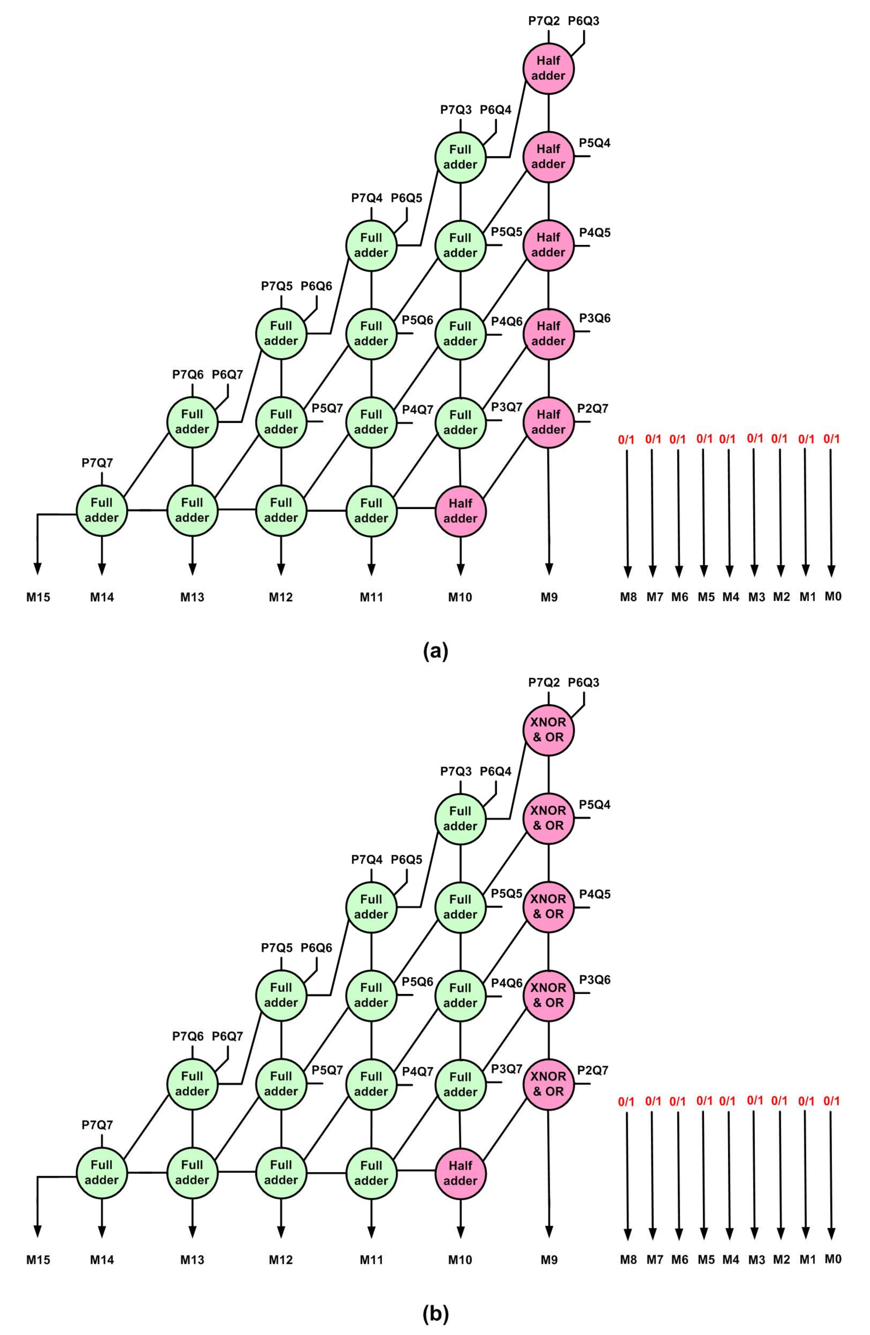
The schematic of an 8 × 8 EAM is shown in
Figure 1, where P7 to P0 and Q7 to Q0 represent the multiplier inputs, and M15 to M0 represent the product bits. In the multiplier inputs, bits P7 and Q7 are the most significant while bits P0 and Q0 are the least significant. In the multiplier output, bit M15 is most significant while bit M0 is the least significant. An 8 × 8 EAM generates 64 partial products which can be realized using an array of 2-input AND gates. In
Figure 1, P7Q7 up to P0Q0 represent the 64 partial products, which result from the multiplication of input bits P7 to P0 with Q7 to Q0. The EAM incorporates a carry save adder comprising half adders and full adders, where the carry outputs generated from the half adders and/or full adders in one logic level are passed on as carry inputs to the half adders and/or full adders present in the next logic level. A binary half adder adds two input bits and produces a sum bit and any carry overflow, while a binary full adder adds two input bits including any carry input and produces a sum bit and any carry overflow. An 8 × 8 EAM comprises 8 half adders and 48 full adders.
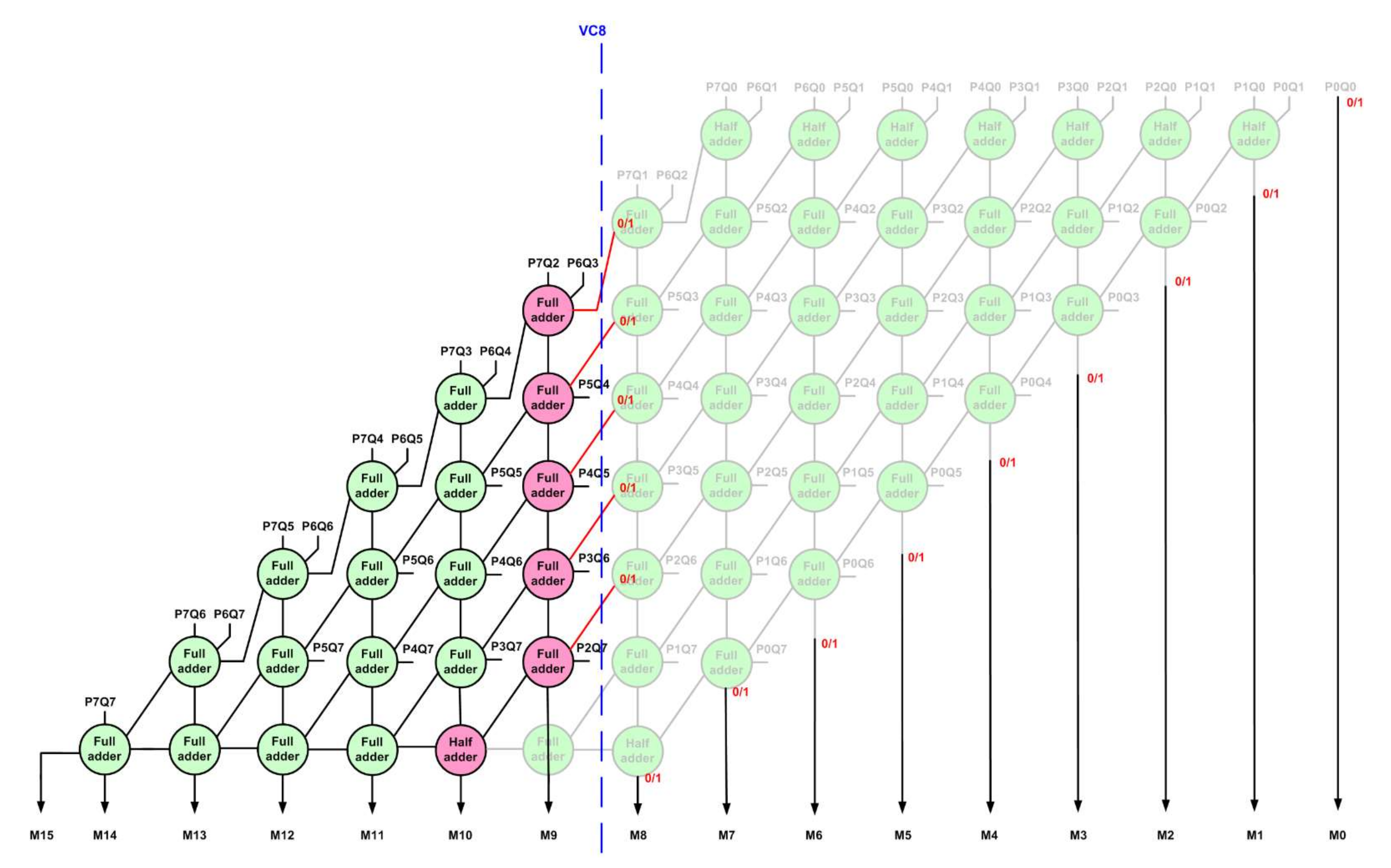
In
Figure 1, vertical cuts labelled as VC0 up to VC13 are shown as examples by blue dashed lines, and any of these vertical cuts may be made in an EAM to generate an IAM. Basically, after making a vertical cut in an EAM, the circuit portion on the right side of the cut will be eliminated and the circuit portion on the left side of the cut would be retained, but with some modification. The deeper the vertical cut, more logic would be eliminated, and hence, more inaccuracy would be introduced in the multiplication. For example, vertical cut VC0 would eliminate just one 2-input AND gate, whereas vertical cut VC2 would eliminate five 2-input AND gates which realize the partial products P2Q0, P1Q1, P1Q0, P0Q1, and P0Q2; one 2-input AND gate that produces M0; and 2 half adders and 1 full adder. Therefore, the choice of a vertical cut should be made commensurate with the extent of inaccuracy that would be deemed acceptable for a practical application. For an illustration,
Figure 2 shows the result of a vertical cut VC8 made on the EAM. The circuit portion on the right side of VC8 is eliminated. The full adders shown in rose in
Figure 2 have one of their inputs cut, which are referred to as dangling inputs; these may be assigned a constant binary value of 0 or 1. The full adder that produces product bit M9 in
Figure 1 has both its inputs cut in
Figure 2, so it is eliminated; the sum output of the full adder present above it is now labelled as M9. The full adder that produces product bit M10 in
Figure 1 has one of its inputs cut in
Figure 2, so it is converted to a half adder, which is shown in rose. After making the vertical cut VC8 on the EAM, product bits M8 up to M0 will become dangling, and hence, they can be assigned a constant binary value of 0 or 1, as shown in
Figure 2. Given these, after making a vertical cut on an EAM, four generalized IAM architectures can be derived, which are given as follows:
IAM00–binary 0 is assigned to the dangling input of the full adders (shown in rose), and binary 0 is assigned to the dangling product bits (here, M8 up to M0)
IAM01–binary 0 is assigned to the dangling input of the full adders (shown in rose), and binary 1 is assigned to the dangling product bits (here, M8 up to M0)
IAM10–binary 1 is assigned to the dangling input of the full adders (shown in rose), and binary 0 is assigned to the dangling product bits (here, M8 up to M0)
IAM11–binary 1 is assigned to the dangling input of the full adders (shown in rose), and binary 1 is assigned to the dangling product bits (here, M8 up to M0)
Among the above, IAM00 architecture was presented in [
16,
17], and IAM01, IAM10, and IAM11 architectures are our propositions. IAM00 and IAM10 architectures have a commonality in that the dangling product bits are assigned a binary 0, and IAM01 and IAM11 architectures have a commonality in that the dangling product bits are assigned a binary 1.
When binary 0 is given as an input to the full adders shown in rose in
Figure 2, they would be transformed into half adders. To explain this, let us presume that A, B, and C represent the inputs of a full adder, and SUM and COUT represent its sum and carry outputs, which are expressed by SUM = A⊕B⊕C and COUT = (A⊕B) C + AB, respectively. Supposing one of the inputs, say C, is assigned a binary 0, then SUM = A⊕B and COUT = AB, which represent the equations of a half adder. Therefore, the full adders shown in rose in
Figure 2 can be replaced by half adders, which is applicable to IAM00 and IAM01 architectures. Alternatively, if say C is assigned a binary 1 (i.e., binary 1 is given as an input to the full adders shown in rose in
Figure 2), then SUM = A⊙B, and COUT = A + B, which can be realized using a 2-input XNOR gate and a 2-input OR gate. Hence, the full adders shown in rose in
Figure 2 can be reduced to the combination of a 2-input XNOR gate and a 2-input OR gate, which is applicable to IAM10 and IAM11 architectures.
The IAMs resulting from the vertical cut VC8 made on an 8 × 8 EAM, after performing the above-mentioned logic optimization, is shown in
Figure 3, where
Figure 3a depicts examples of IAM00 and IAM01 architectures, and
Figure 3b depicts examples of IAM10 and IAM11 architectures. Referring to
Figure 3a, IAM00 would have product bits M8 up to M0 assigned a binary 0, and IAM01 would have product bits M8 up to M0 assigned a binary 1. Referring to
Figure 3b, IAM10 would have product bits M8 up to M0 assigned a binary 0, and IAM11 would have product bits M8 up to M0 assigned a binary 1.
3. Error Metrics of Inexact Array Multipliers
We calculated two widely used error metrics for the IAMs, namely the mean absolute error (MAE) and the root mean square error (RMSE). Among these, RMSE is more useful as it effectively quantifies the extent of signal degradation in digital signal processing [
18]. An 8 × 8 multiplier would have a total of 2
16 distinct inputs; the entire set of distinct inputs was considered to accurately calculate MAE and RMSE for different IAMs. Towards this, Python models of 8 × 8 EAM and 8 × 8 IAMs were developed. For each distinct input supplied, the absolute difference between the product produced by the EAM and the product produced by each IAM was calculated to subsequently calculate MAE and RMSE for the IAMs. MAE and RMSE were calculated using Formulas (1) and (2). In Formulas (1) and (2),
denotes the product of an EAM with inputs P and Q, and
denotes the product of an IAM with the same inputs of P and Q.
Generally, the reductions in design metrics such as critical path delay, area, and power dissipation for an inexact circuit compared to the exact circuit would depend on the extent of inaccuracy incorporated [
19]. The extent of inaccuracy incorporated is typically proportional to the savings in design metrics achievable for an inexact circuit compared to the exact circuit. However, output quality (referring to the quality of blended images here) assumes a greater priority than the savings in design metrics gained for an inexact circuit compared to the exact circuit. Therefore, incorporating an optimum (i.e., maximum allowable) inaccuracy in an inexact circuit commensurate with a target application is more important than achieving significant savings in the design metrics. An optimum inaccuracy implies achieving a good trade-off between output quality and circuit performance in inexact computing. Choosing a less-than-optimum inaccuracy would pave the way for increased accuracy in the computation (here, multiplication) but would also mean including more logic and therefore would result in reduced savings in design metrics for an inexact circuit compared to the exact circuit. On the other hand, choosing a more-than-optimum inaccuracy implies aggressive reduction of logic to greatly reduce the design metrics, but at the expense of compromising on the output quality, which may not be acceptable for a target application. Therefore, a more-than-optimum inaccuracy is not preferable.
For the image blending application, based on repeated experimentation, we found that vertical cut VC8 corresponds to an optimum inaccuracy, as noted in [
14]. Given this, vertical cuts VC0 up to VC7 would be construed as leading to less-than-optimum inaccuracy, and vertical cuts VC9 to VC13 would be construed as leading to more-than-optimum inaccuracy. We calculated MAE and RMSE for IAMs corresponding to vertical cuts VC6 up to VC10 covering two less-than-optimum, one optimum, and two more-than-optimum representative inaccuracy conditions; the respective error metrics are given in
Table 1. In
Table 1, the label of the vertical cut is mentioned as a suffix to the IAM architectures for clarity. Optimum MAE and RMSE values obtained for an IAM corresponding to each vertical cut have been shown in boldface.
From
Table 1, it can be seen that the IAM01 architecture consistently enables reduced MAE and RMSE compared to the other IAM architectures for all the vertical cuts. This is possibly because in the IAM01 architecture, even though the dangling inputs of the full adders (which are shown in rose in
Figure 2) are assigned binary 0, which may impact the value of product bit M9, this would be compensated by the assignment of a binary 1 to the less significant product bits viz. M8 up to M0. Hence, there is a likelihood for an internal error compensation to happen in the IAM01 architecture, which is the possible reason for its reduced error metrics compared to other IAM architectures. This suggests that the IAM01 architecture is likely to result in better quality of blended images compared to the quality of blended images obtained using other IAM architectures. The IAM11 architecture shares a commonality with the IAM01 architecture, given the fixed assignment of binary 1 to product bits M8 up to M0. However, in the case of IAAM11 architecture, binary 1 is input to all the full adders (shown in rose in
Figure 2), which may exacerbate the error in the internal computation due to the higher significance of product bits M9 up to M16; this is possibly the reason why the IAM11 architecture consistently reports greater MAE and RMSE compared to the other IAM architectures for all the vertical cuts. IAM10 architecture, which also has a constant binary 1 assigned to the full adders (shown in rose in
Figure 2), like the IAM11 architecture, reports reduced error in comparison; this is because product bits M8 up to M0 of IAM10 architecture are assigned a binary 0 unlike the IAM11 architecture, thus resulting in relatively less error. In the case of IAM00 architecture, although product bits M8 up to M0 are assigned a binary 0, and a binary 0 is given as an input to the full adders (shown in rose in
Figure 2), the assumption of a value of 1 by any significant product bit ranging from M9 up to M16 is likely to overshadow the error arising from the constant assignment of a binary 0 to the less significant product bits M8 up to M0. Therefore, the overall error of IAM00 architecture is likely to be lesser compared to IAM10 and IAM11 architectures, but not lesser than the IAM01 architecture, which inherently features error compensation. Hence, from the perspective of error metrics (given in
Table 1), IAM01 architecture is found to be preferable to the other IAM architectures.
4. Digital Image Blending
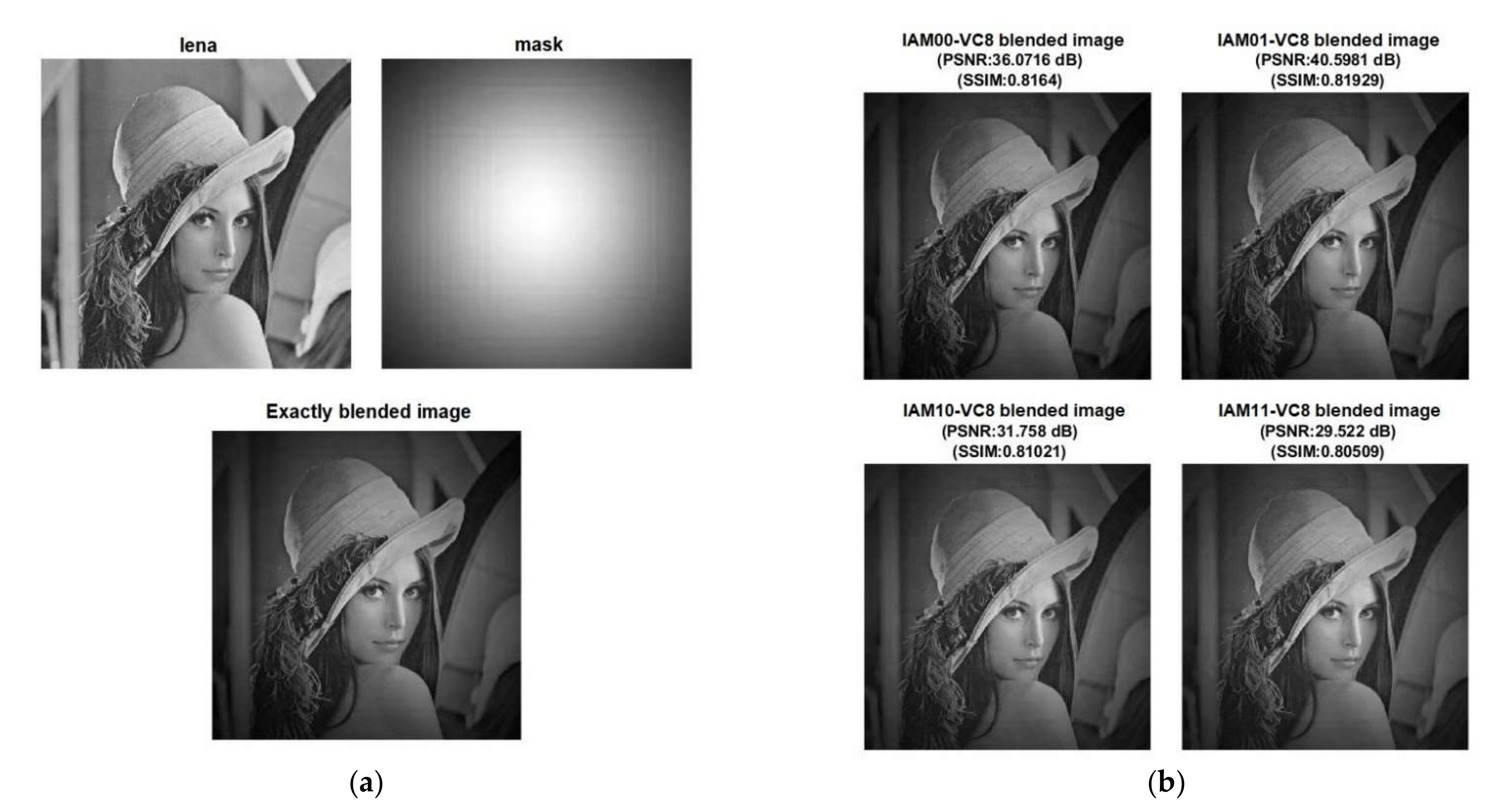
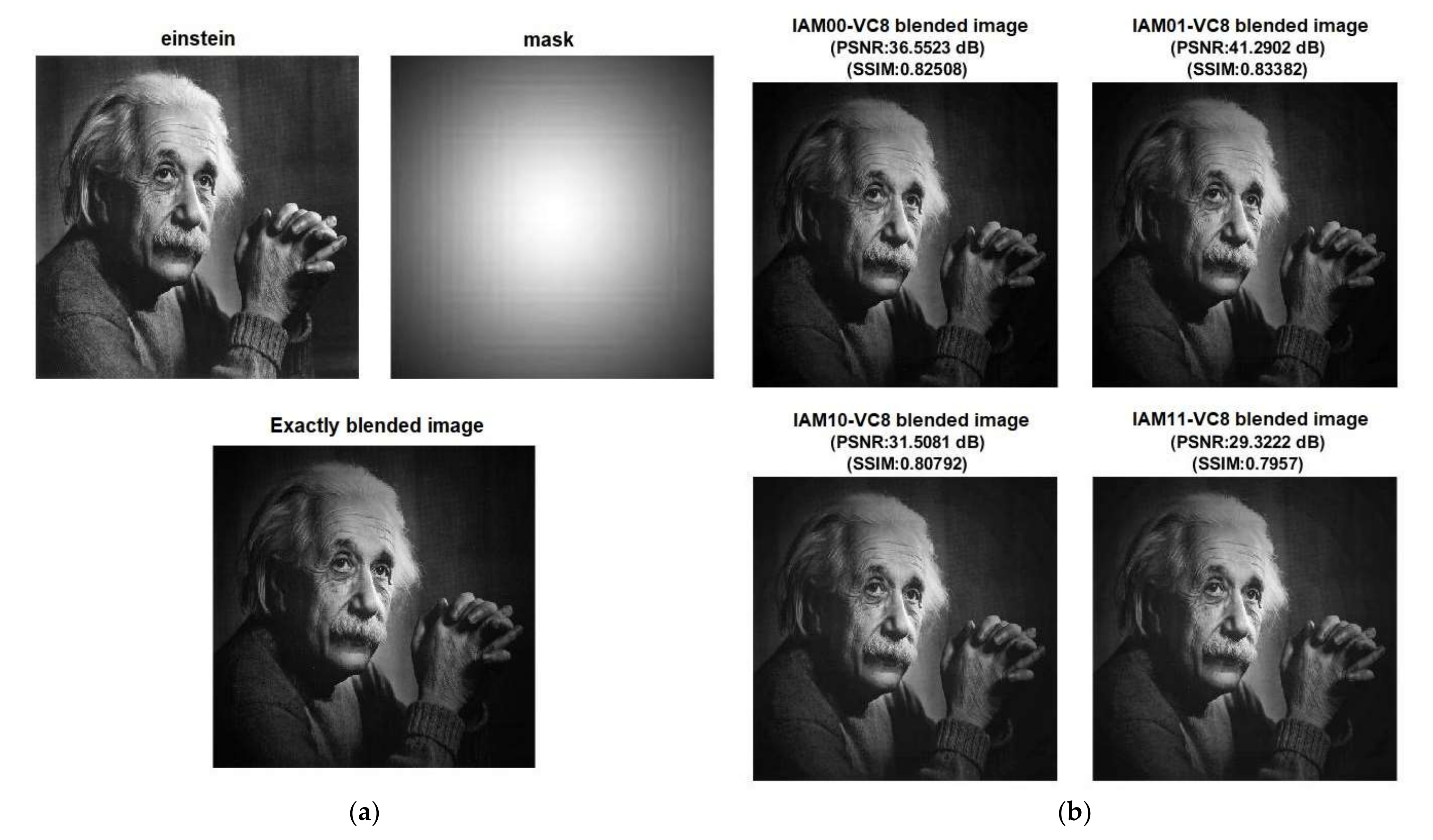
Digital image blending has been considered as a practical application to evaluate the performance of different IAMs versus the EAM. Two digital images of size 512 pixels × 512 pixels were considered for blending, and their grayscale resolution is 8 bits. The blended image is also of size 512 pixels × 512 pixels. The gray values of the images are multiplied pixel by pixel, and the grayscale resolution of the blended image is 16 bits. We considered some standard digital images from [
20] viz.
Lena,
cameraman,
Einstein, and
woman with dark hair for blending with a
mask image.
Figure 4,
Figure 5,
Figure 6 and
Figure 7 show the blended images obtained via exact and inexact multiplications.
Figure 4a,
Figure 5a,
Figure 6a and
Figure 7a show the original images and the blended images obtained by exact multiplication. It was shown in [
14] that vertical cut VC8 represents an optimum inaccuracy with respect to image blending.
Figure 4b,
Figure 5b,
Figure 6b and
Figure 7b show the blended images obtained by inexact multiplication using different IAMs corresponding to vertical cut VC8 made on the EAM.
To measure the quality of blended images, popular figures of merit such as peak signal-to-noise ratio (PSNR) [
21] and structural similarity index metric (SSIM) [
22] were used. PSNR is measured in decibels (dB). PSNR is infinite for the exactly blended image since no noise is introduced in the exact computation, whereas a finite PSNR results for the inexactly blended images due to the introduction of noise owing to inexact computation. Nevertheless, a high PSNR is preferred for the inexactly blended images, which is indicative of less distortion. Typically, a PSNR greater than 30 dB is preferred for 8-bit digital image processing [
21]. SSIM is a measure of the structural similarity between a reference image (i.e., an exactly blended image) and a target image (i.e., an inexactly blended image). SSIM ranges from decimal 0 to 1, with decimal 0 indicating that the reference image and the target image are completely different and decimal 1 indicating that the reference image and the target image are the same. A high SSIM is preferred for an inexactly blended image, which indicates good similarity with the exactly blended image. The visual differences between the inexactly blended images in
Figure 4b,
Figure 5b,
Figure 6b and
Figure 7b may be noticed upon close observation. Nevertheless, PSNR and SSIM are scientific metrics which can be used to ascertain the real quality of inexactly blended images obtained using different IAMs and to distinguish the difference in quality between them. From
Figure 4b,
Figure 5b,
Figure 6b and
Figure 7b, it can be seen that the IAM01 architecture (i.e., IAM01-VC8) consistently enables greater PSNR and SSIM for the inexactly blended images compared to the other IAM architectures. This is possibly due to the reduced error metrics (MAE and RMSE) of the IAM01 architecture compared to the other IAM architectures, as evident from
Table 1.
5. Implementation and Design Metrics
We structurally described an exact 8 × 8 EAM and many 8 × 8 IAMs resulting from vertical cuts VC6 up to VC10 made on the EAM in Verilog HDL. We also behaviorally described an 8 × 8 exact multiplier in Verilog HDL by using the multiplication operator (*). These multipliers were then synthesized for high speed by a logic synthesis tool (Synopsys Design Compiler) using a 32/28 nm CMOS standard digital cell library [
23]. The default wire load model (parasitic) was included in the synthesis, and a fanout-of-4 drive strength was assigned to the output ports i.e., to the product bits of multipliers. A typical case high-V
t CMOS process with a supply voltage of 1.05 V and an operating temperature of 25 °C was considered for synthesis and simulation. The gate-level netlists of the multipliers generated by Synopsys Design Compiler were verified by performing functional simulations using Synopsys VCS, and the switching activity was recorded for power estimation. For functional simulations, a test bench comprising about 1000 random input vectors was supplied to the multipliers at a timing of 2.5 ns (400 MHz). After synthesis, the design metrics of the multipliers were estimated, which are given in
Table 2. The total area of the multipliers, including cell area and interconnect area, was estimated using Synopsys Design Compiler; the critical path delay was estimated using Synopsys PrimeTime; and the average power dissipation was estimated using Synopsys PrimePower.
From
Table 2, it can be seen that IAM00 and IAM01 architectures feature the same design metrics, and IAM10 and IAM11 architectures also feature the same design metrics. As mentioned earlier, the difference between IAM00 and IAM01 architectures is that the dangling product bits (resulting from a vertical cut made on an EAM) are assigned binary 0 in the former and assigned binary 1 in the latter. The same difference manifests between IAM10 and IAM11 architectures. Binary 0 or 1 is assigned to a dangling product bit (arising from a vertical cut) by connecting it to ground or supply using a tie to low (TIEL) or a tie to high (TIEH) standard library cell. Since TIEL and TIEH cells of [
23] have the same characteristics; therefore, IAM00 and IAM01 architectures have the same design metrics since their internal logic is the same, and likewise, IAM10 and IAM11 architectures also have the same design metrics as their internal logic is the same.
It can be seen from
Table 2 that as the order of the vertical cut increases, more logic is reduced and the critical path becomes shorter; hence, the reductions in design metrics increase for the IAMs compared to the exact multiplier and EAM. Compared to the 8 × 8 EAM, the exact 8 × 8 multiplier that was described using the multiplication operator and automatically synthesized for high speed by Design Compiler reports 12.5% reduction in critical path delay, 7.4% lesser area occupancy, and 21.5% reduction in power dissipation. It was noted in the previous sections that vertical cut VC8 made on the EAM is acceptable for image blending and the IAM01 architecture is preferable to its counterparts in terms of the quality of blended images and error metrics. Given this, IAM01-VC8 reportedly achieves the following reductions in design metrics compared to the exact multipliers: (i) 9.7% reduction in critical path delay, 60.6% reduction in area, and 64.7% reduction in power dissipation compared to the high-speed exact 8 × 8 multiplier that was auto-synthesized, and (ii) 21% reduction in critical path delay, 63.3% reduction in area, and 72.3% reduction in power dissipation compared to the 8 × 8 EAM.
For digital circuits and systems, the product of power dissipation and critical path delay (called PDP), representing energy, serves as a low-power figure of merit. Given this, we calculated PDP for exact and inexact multipliers, plotted in
Figure 8. The PDP of the exact multiplier is plotted in blue, the PDP of EAM is plotted in purple, the PDP of IAM architectures corresponding to vertical cut VC6 is plotted in orange, the PDP of IAM architectures corresponding to vertical cut VC7 is plotted in green, the PDP of IAM architectures corresponding to vertical cut VC8 is plotted in red, the PDP of IAM architectures corresponding to vertical cut VC9 is plotted in black, and the PDP of IAM architectures corresponding to vertical cut VC10 is plotted in pink. Obviously, as the order of the vertical cut increases, the PDP of IAMs decreases due to a decrease in their design metrics, as noted from
Table 2. From
Figure 8, IAM01-VC8, which is suitable for image blending, achieved 68.1% reduction in energy compared to the high-speed exact 8 × 8 multiplier and 78.1% reduction in energy compared to the 8 × 8 EAM.
6. Conclusions
Blending of digital images is commonly performed in computer graphics and photo editing applications. In this work, we analyzed the usefulness of inexact multiplication for image blending by comparison with exact multiplication. Towards this, we considered the blending of 8-bit images exactly and inexactly by employing exact and inexact multipliers, respectively. Different IAMs were derived by making vertical cut(s) on an EAM, and constant binary values were assigned to the dangling inputs and dangling product bits. Among the four IAM architectures, IAM01 architecture was found to be better in terms of having reduced error metrics (MAE and RMSE). Consequently, the IAM01 architecture was found to consistently yield better quality blended images compared to the other IAM architectures, where the quality of blended images has been quantified using standard metrics such as PSNR and SSIM. Vertical cut VC8 made on an EAM was found to be acceptable for 8-bit image blending, and based on the experimentation, the quality of blended images obtained using IAM01-VC8 was found to be acceptable in comparison with the quality of blended images obtained using the exact multiplier. The exact and inexact multipliers were implemented using a 32/28 nm CMOS standard cell library, and it was noted that whilst yielding blended images of acceptable quality, IAM01-VC8 achieved reductions in all the design metrics compared to the exact high-speed 8 × 8 multiplier and the 8 × 8 EAM. Notably, IAM01-VC8 consumes only 32% of the energy of an exact 8 × 8 multiplier and 22% of the energy of an 8 × 8 EAM.


