1. Introduction
With the enormous development of different electronic and electrical devices, wireless power transfer (WPT) has become a very popular topic of research nowadays, because WPT is a more reliable and convenient approach for power transmission than traditional power transmission with wires. WPT is especially important when it is necessary to charge batteries dynamically (while moving) or charge batteries statically when a charging object operates in an automatic mode (such as mobile robots in warehouses) [
1,
2,
3,
4]. In fact, the static charging of the batteries of mobile robots has attracted a remarkable amount of attention from both the research and the engineering communities, due to the absence of sparking (it is especially important if mobile robots operate at chemical plants), high reliability (no problems with mobile robots’ contacts wearing down), no need for very accurate positioning (some misalignment of the WPT coils does not lead to a disruption of the charging process), etc. [
1,
5].
Although different approaches for wireless power transmission exist, in applications, such as the static charging of the batteries of mobile robots, an inductive-resonant approach is the most useful, as it has a high enough efficiency for small-gap applications [
6] when electric power should be transferred wirelessly over a distance up to some tens of cm. Usually, the inductive-resonant WPT systems are designed to operate within the range of kHz (e.g., within the frequency ranges of 80–90 kHz or 100–200 kHz); however, sometimes they can also be designed to operate within the range of MHz (e.g., at 6.78 MHz) to achieve a higher transmission distance, better spatial freedom and a smaller size.
Due to the presence of switch mode power converters inside, the inductive-resonant WPT systems are the potential sources of electromagnetic emissions (EME) which can cause electromagnetic interference (EMI) to sensitive electronic devices, such as mobile phones [
7]. As it is shown in
Figure 1, EME can take the form of conducted EME propagating through input wires to an electric grid and radiated EME (time-varying magnetic fields or even radio waves), which can disrupt the normal operation of sensitive electronic devices. Therefore, the EME must be reduced. This paper is devoted to the reduction of conducted EME.
WPT systems are often considered as industrial, scientific and medical (ISM) devices. Therefore, they should comply with the requirements of the CISPR 11 standard [
8]. As it is shown in
Figure 1, WPT systems can be connected to either utility AC or local DC electric grids. With an ever-growing interest in renewable energy, DC microgrids have become widespread in both residential and industrial sectors. Therefore, WPT systems can often be connected to DC microgrids and make the EMI conducted to sensitive electronic devices connected to the same grid [
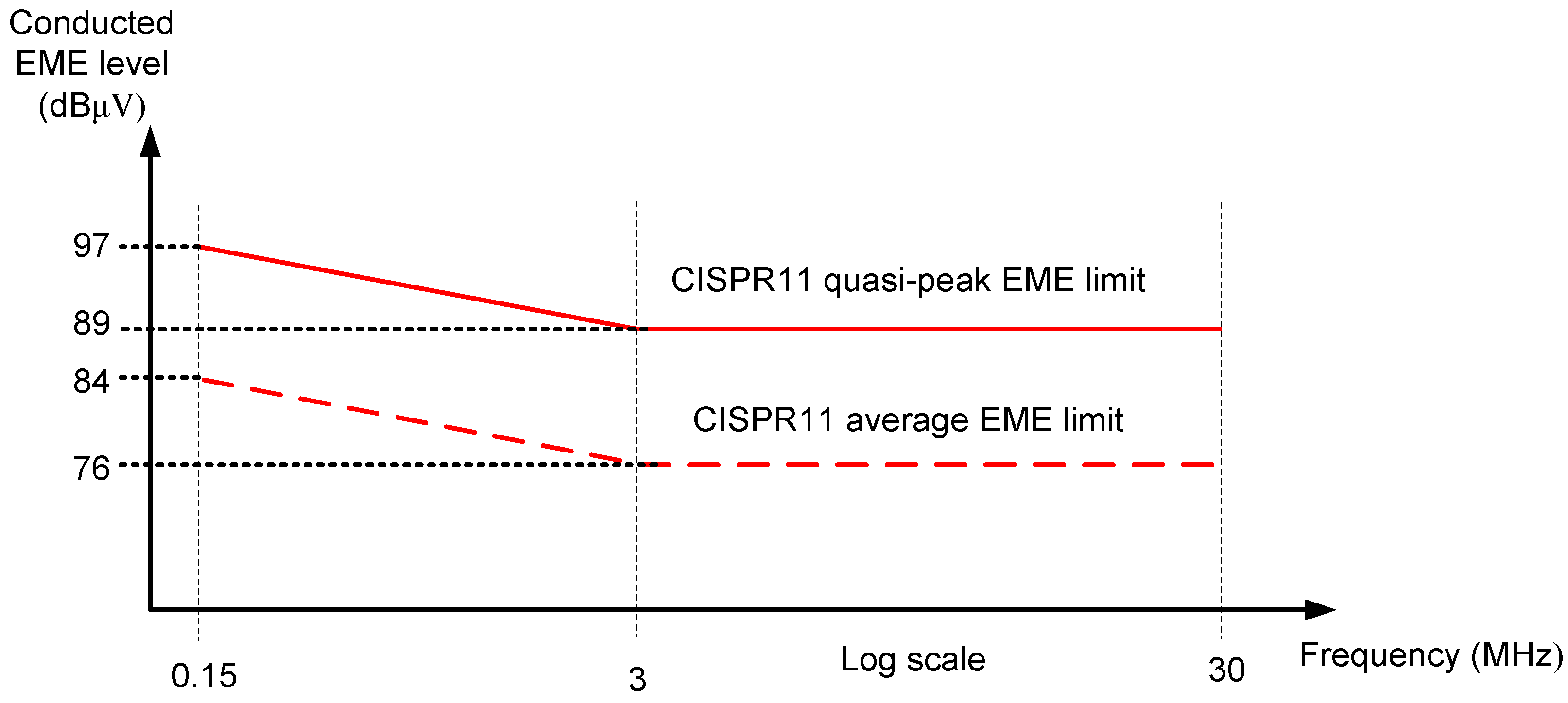
9]. As an example, the maximum allowable conducted EME limits for Group 1 industrial electrical devices connected to a DC grid are shown in
Figure 2.
A classical approach for conducted EME reduction—input conducted EME filters—adds noticeable cost, size and weight to the inductive-resonant WPT system. Therefore, a spread spectrum technique based on WPT inverter switching frequency modulation has been applied to the inductive-resonant WPT systems [
10,
11,
12,
13]. A typical approach for the reduction of radiated EME is electromagnetic shielding, but the shields are quite expensive and they increase the size and cost of the WPT systems. In contrast to filtering and shielding, the spread spectrum approach does not require increases in size, cost or weight of WPT systems, because it can be implemented by using a microcontroller with a suitable program code.
There are different papers related to the suppression of conducted EME using the spread spectrum approach in the inductive-resonant WPT systems [
10,
11,
12,
13] which show that the spread spectrum technique along with moderate conducted EME reduction can lead to some “adverse effects”, mainly in terms of the decrease in efficiency. Moreover, as pointed out in [
13], the conducted EME reduction coefficient is not high because of the uneven distribution of the conducted EME energy within the first harmonic sidebands, especially for higher switching frequency deviations. Thus, it is of great importance to propose an improved spread spectrum approach that can give a noticeably better conducted EME reduction along with a better efficiency. Therefore, the novelty of this paper (this paper is partly based on the results of a Master’s thesis [
14]) is an improved spread spectrum approach—the multi-switching frequency and multi-duty cycle (MFMD) scheme—in which the inductive-resonant WPT system can operate at multiple switching frequencies (e.g., 3 different frequencies) and as a part of a control signal with a specific switching frequency, there is a specific duty cycle. As it will be shown in the paper, the advantages of the proposed spread spectrum technique are: (1) due to the more even distribution of EME energy within the first-harmonic sidebands, it can give a better conducted EME reduction than conventional conducted EME reduction techniques; (2) a better efficiency of WPT system; (3) it is a simple approach because it can be implemented by using even an inexpensive 8-bit microcontroller, such as Atmega AVR 328p. Despite the fact that the proposed spread-spectrum approach is applied to a WPT system connected to a local 48-V DC grid, it can also be applied to a WPT system connected to AC grid to improve performance of the WPT system. The research is important because it contributes to the development of low-EME inductive-resonant WPT systems with improved performance characteristics.
The paper is organized as follows: the proposed spread spectrum approach is explained in detail in
Section 2; the experimental setup is described in
Section 3; the experimental results are presented and discussed in
Section 4; and finally, conclusions are given in
Section 5.
3. Experimental Setup
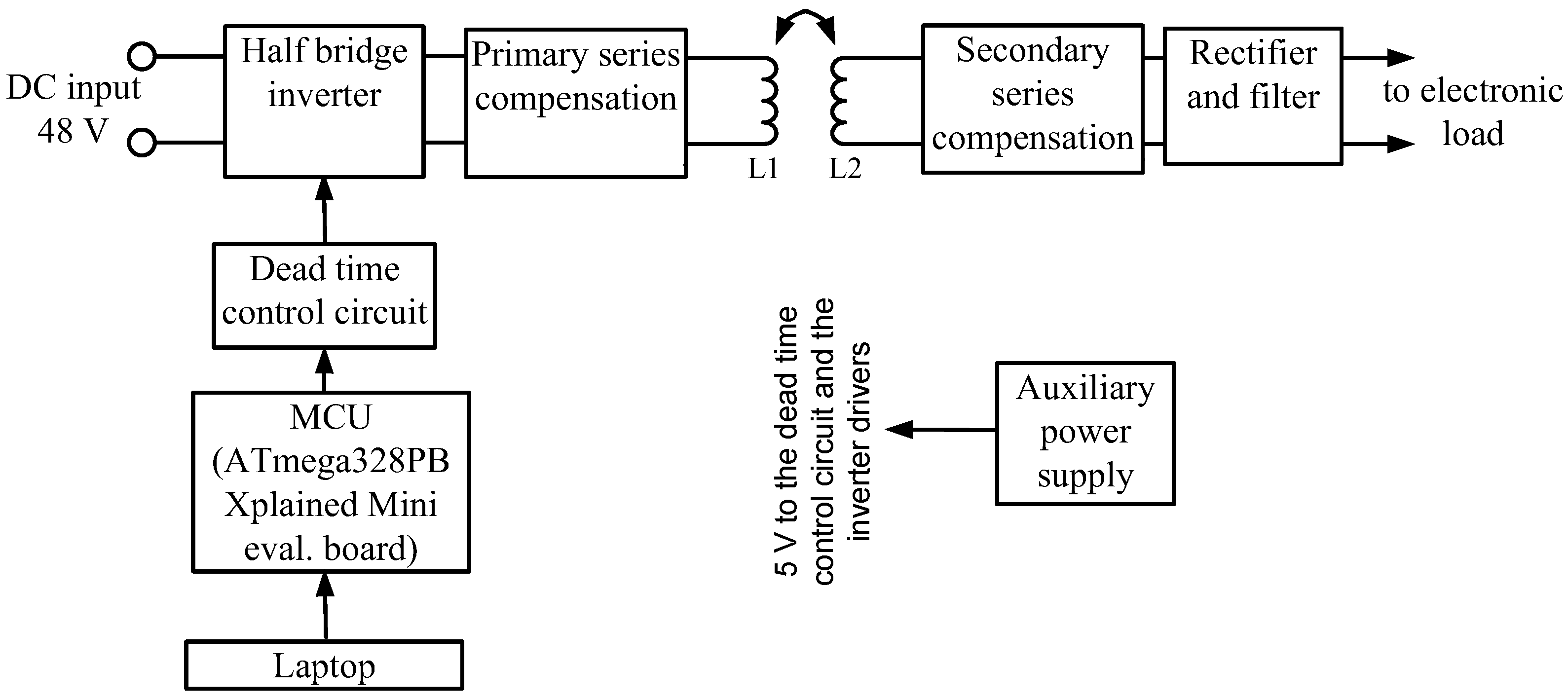
In order to study the effect of the conventional spread-spectrum technique and MFMD spread spectrum technique (in our case it is 3F3D technique) on the conducted EME of the inductive-resonant WPT system, an experimental prototype of the system has been designed and practically built. A block diagram of the prototype is presented in
Figure 8. It consists of a half-bridge inverter (from GaN systems), the half-bridge inverter dead time control circuit (homemade), a microcontroller (ATmega328PB Xplained Mini evaluation board), the primary-side and the secondary-side series compensation circuits (based on multiple capacitors), the self-made transmitting and receiving coils L
1 and L
2, respectively (made of suitable litz wire and a 10X10 cm ferrite pad), the secondary-side high-frequency full-wave rectifier with a high-frequency ripple filter (electrolytic and ceramic capacitors connected in parallel) and a simple input conducted EME filter (consisting of a 10 μF electrolytic capacitor connected in parallel to a 1 µF film capacitor). The dead time control circuit generates two square signals to control the inverter transistors adding some time delay to prevent the inverter’s transistors from the shoot-through phenomenon. The half bridge inverter input is connected to the output of 48 V DC power supply. One more power supply is used to feed the control circuits and drivers, except for the microcontroller evaluation board, which is powered by the same laptop used for reprogramming the microcontroller. The primary and the secondary compensation capacitances were calculated so that the primary and secondary-side resonant tanks are tuned to the resonance (at the resonance frequency). The WPT system was designed for the operation within the Qi standard allowed range of frequencies (this is why the central switching frequency
f0 is 170.6 kHz).
The values of the main parameters of the designed inductive-resonant WPT system are shown in
Table 1. The prototype can be used without spread spectrum, with 3F and the proposed 3F3D techniques.
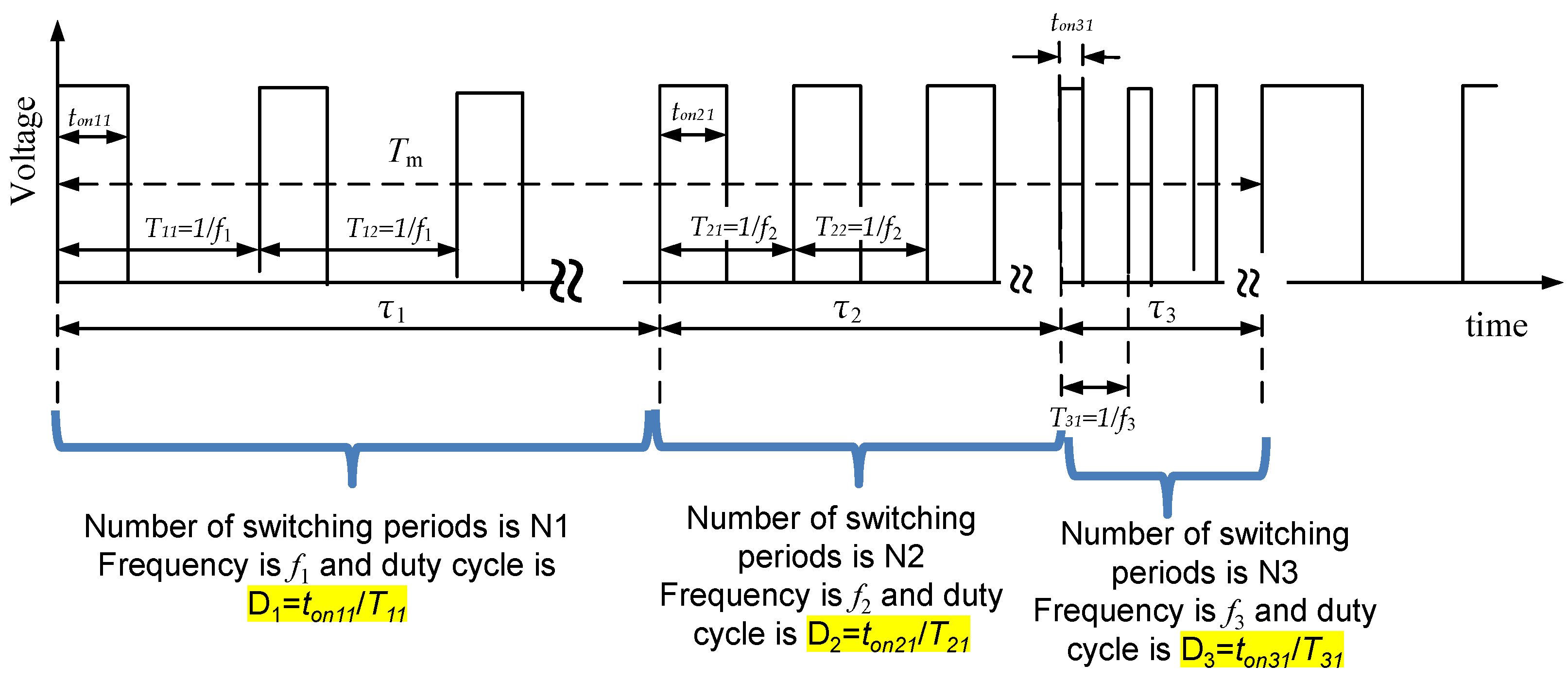
Since the multi switching frequency technique (with 2–4 switching frequencies) or the proposed MFMD technique do not require accurate timings, a cheap low-resolution microcontroller can be used. Thus, for obtaining a square signal with multiple frequencies and duty cycles as shown in
Figure 3 or
Figure 7, we used the microcontroller ATmega328PB Xplained Mini evaluation board. For the generation of the pulse sequence, a direct microcontroller port manipulation (using
delay_us) was used. By composing the microcontroller program code, modulation (repetition) frequency
fm and the maximum difference between switching frequencies Δ
f =
f3 −
f1 can be simply achieved.
A photo of the experimental setup is shown in
Figure 9. To measure the spectrum of the input conducted EME of the WPT system, a mixed domain digital oscilloscope Tektronix MDO4034B with separate spectrum analyzer as well as a homemade DC LISN (according to the circuit diagram presented in
Figure 4) were used. When measuring the efficiency, the output power was measured by using the electronic load, but the input power was measured by using a suitable DC ammeter and a DC voltmeter. During the efficiency measurements, the LISN was disconnected from the circuit. To set different values of the load resistances, the electronic load in constant resistance mode was used.
4. Results and Discussion
The measurements of the conducted EME were made according to the CISPR 11 standard within the frequency range 150 kHz–30 MHz, with the RBW of the spectrum analyzer as 9 kHz (as required by the standard). The main measurements were made for a nominal distance between the coils (2.8 cm), maximum misalignment (1 cm) of the coils and at the load resistance 11.7 Ω (end of CC mode), because in this case the conducted EME levels are the highest. Some measurements were made also for other misalignments of the coils and other resistances of the load. A peak detector was used during the measurements. The obtained results were saved in CSV format files and then post-processed using Matlab. To obtain more accurate results, we used an average of 16 consecutive sweeps.
Despite the fact that the WPT system was examined in an open-loop mode, the average duty cycle of the control signal was adjusted to obtain the same value of output current (in CC mode) or output voltage (in CV mode) regardless the load resistance or the applied spread spectrum technique. This imitation of the closed-loop control made the comparable measurements under different control schemes possible, because when different spread spectrum techniques are applied, the output voltage or current can be changed.
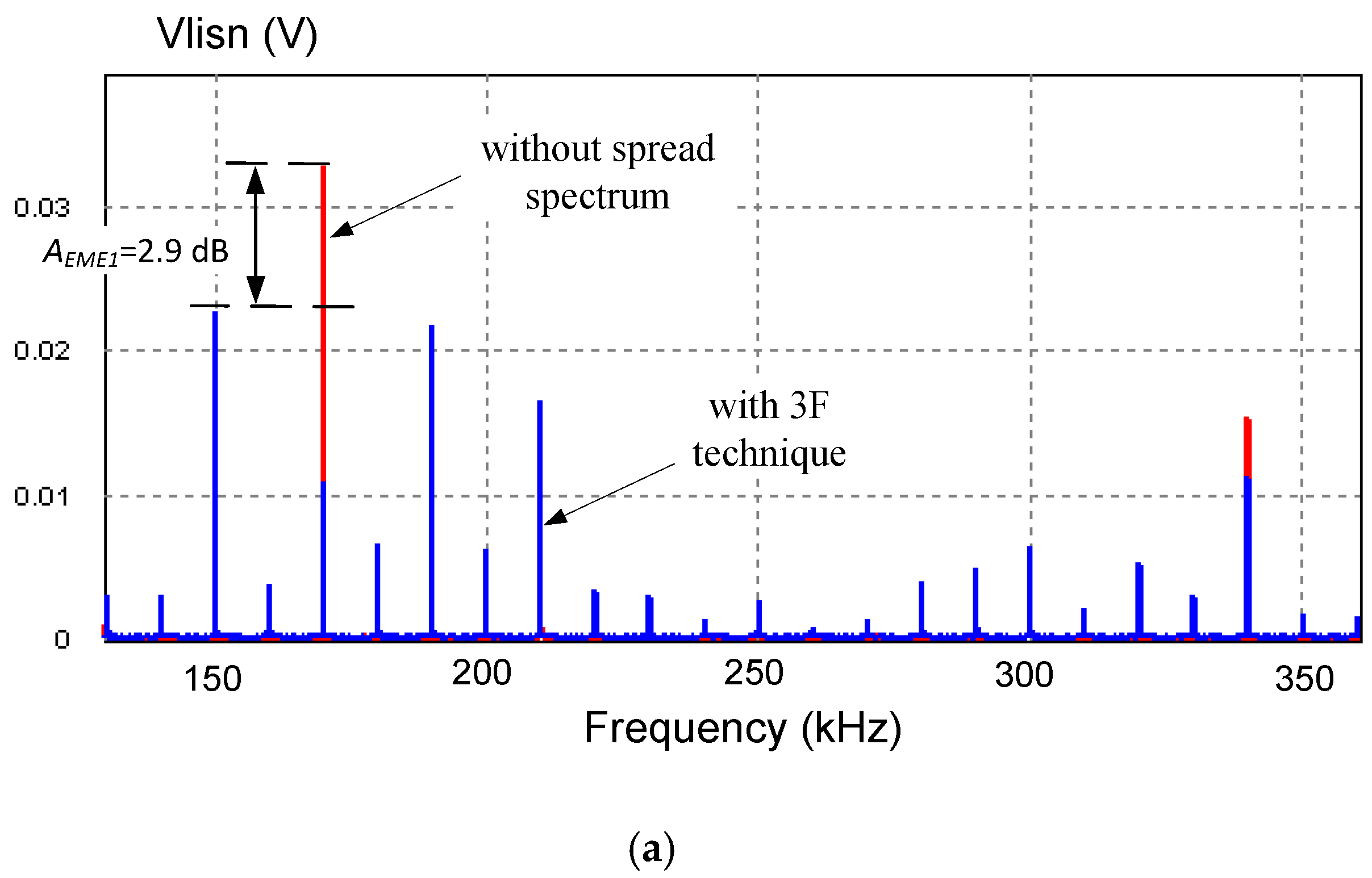
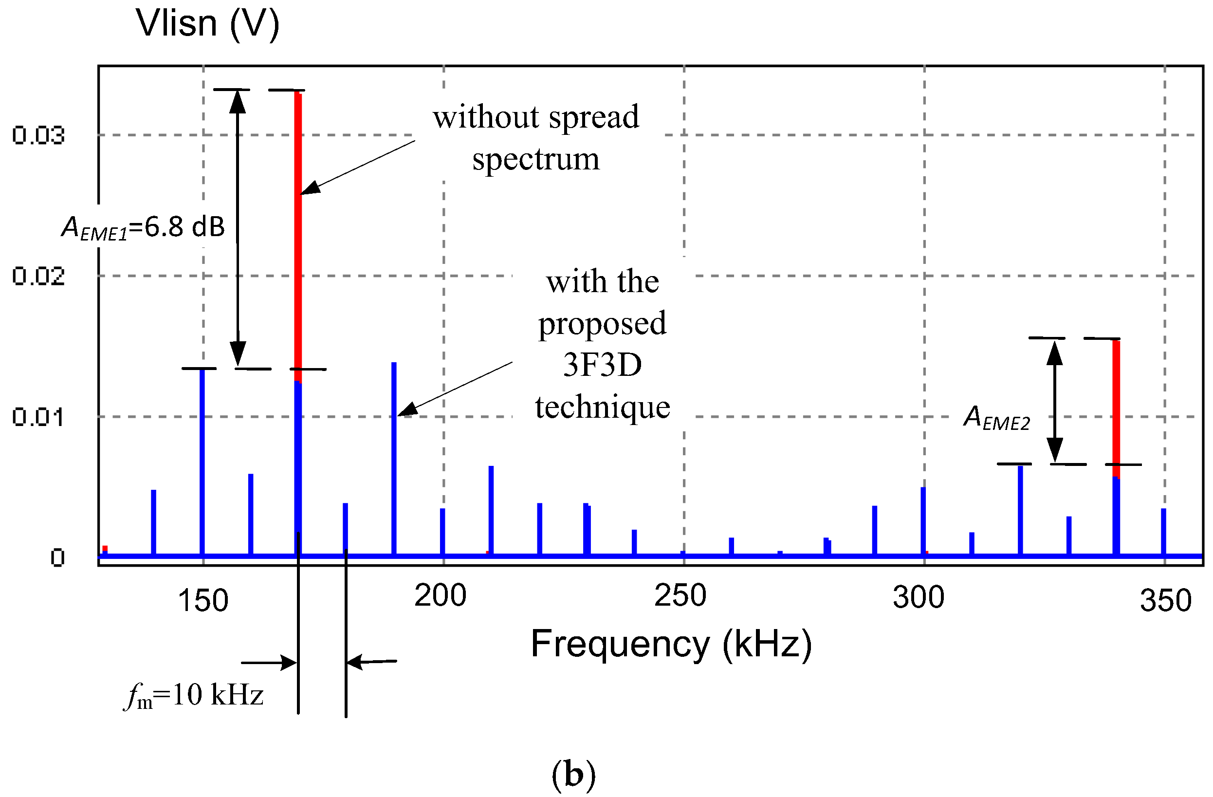
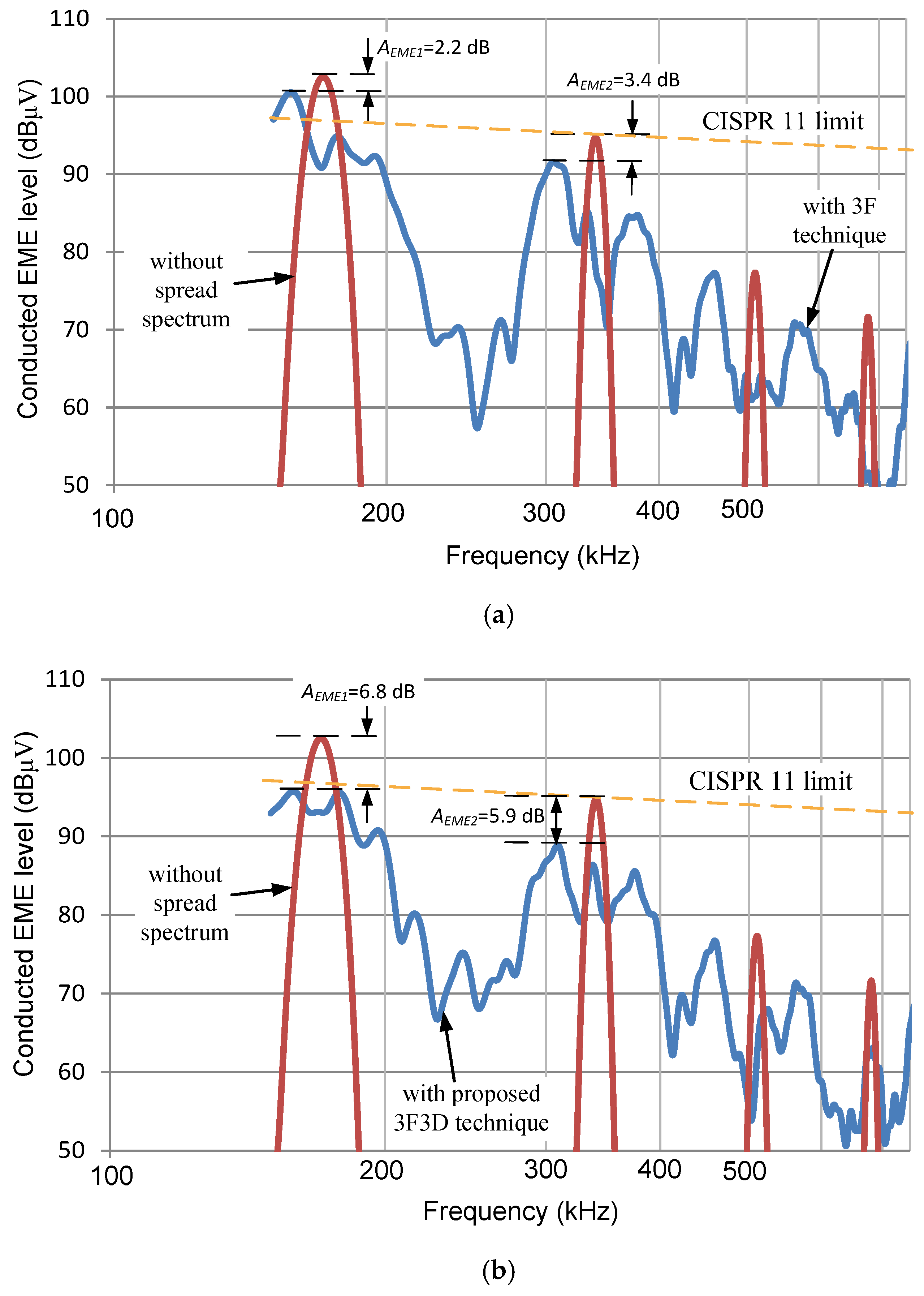
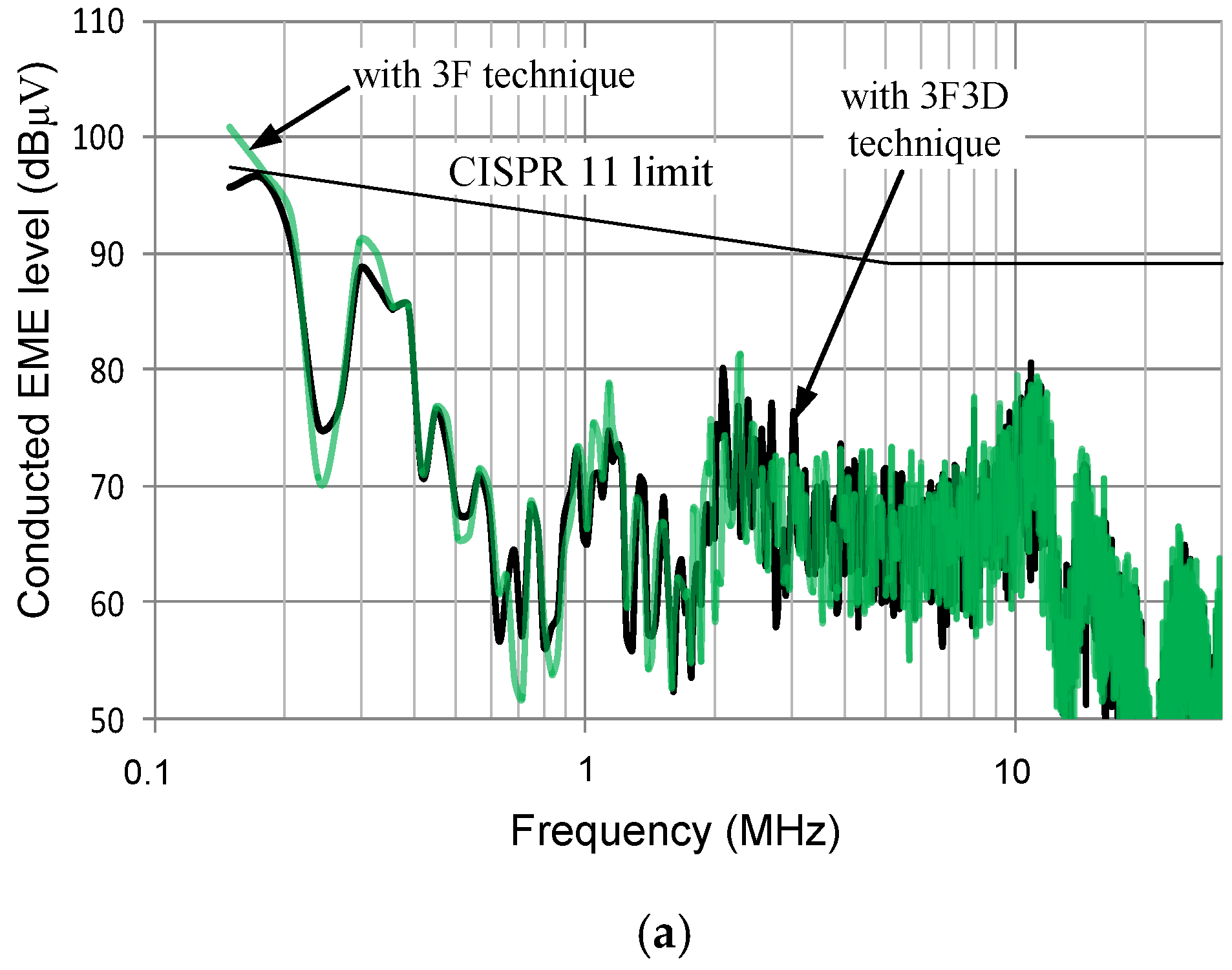
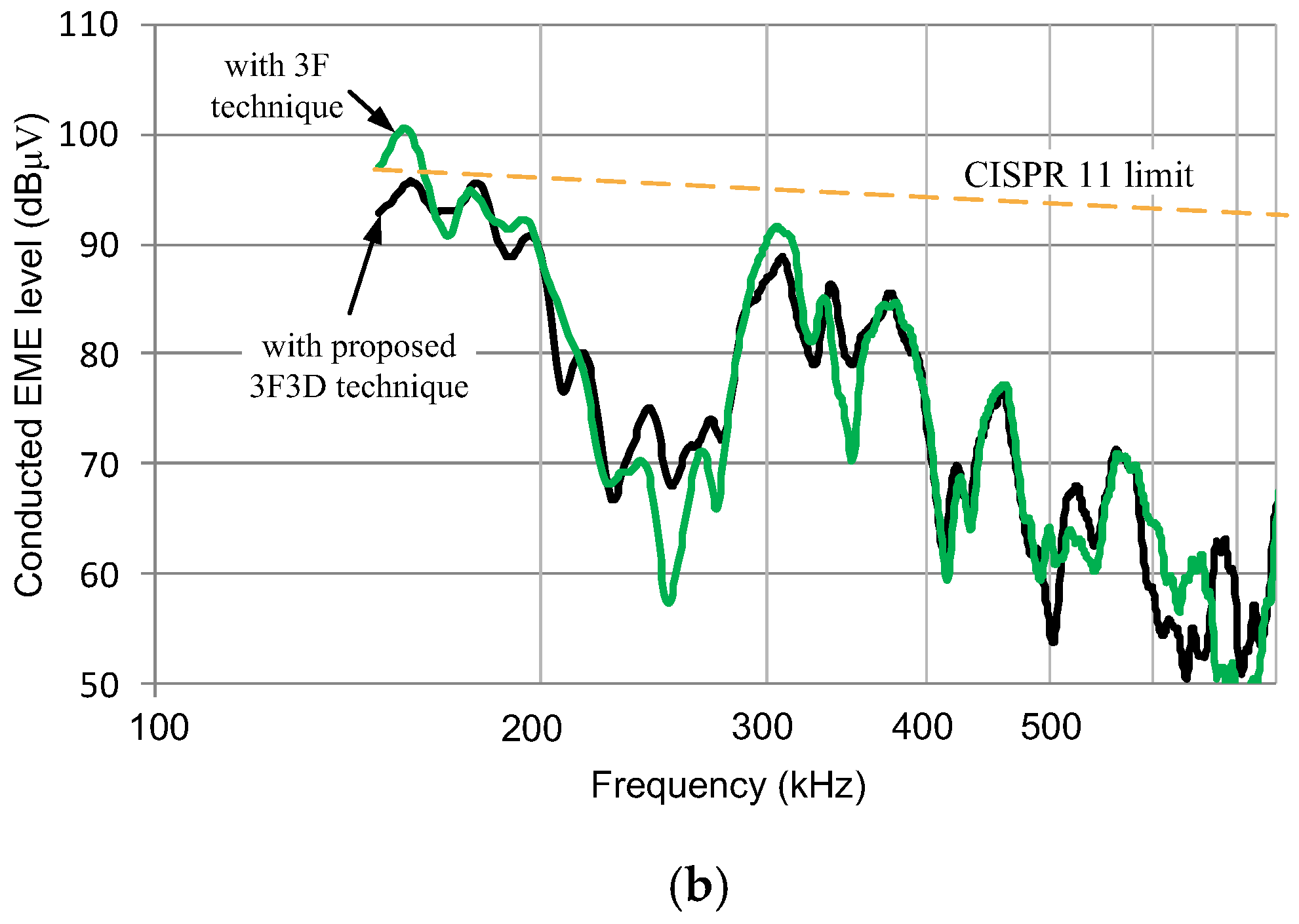
The main measurement results are presented in
Figure 10,
Figure 11 and
Figure 12 and
Table 2. For a reference purposes, CISPR 11 standard (quasi peak) limit lines for industrial (Class A) Group 1 devices connected to a DC grid are also depicted.
In order to quantitatively assess the conducted emission reduction, the reduction coefficient of the amplitude of the fundamental harmonic of the conducted EME (AEME1) and the reduction coefficient of the amplitude of the second harmonic of the conducted EME (AEME2) were calculated from the measurements, because the harmonics are the most dominant ones (especially the fundamental harmonic). Note that the reduction coefficient of the amplitude of the harmonic is the difference (expressed in dB) between the amplitude of the harmonic of the WPT system without the spread spectrum and the maximum value of the amplitudes of the spectrum components of the given harmonic sidebands of the WPT system with the spread spectrum.
Initially the WPT system was examined without the spread spectrum, then with 3-frequency spread spectrum technique and then with the proposed MFMD (3F3D) technique. In all cases, the duty cycles were experimentally determined and their values were added to the program code to obtain the same output DC voltage or current regardless of the control method. For the proposed 3F3D technique, the optimum values of the duty cycles D1, D2 and D3 (for the worst-case coupling coefficient and when the battery equivalent input resistance is at the boundary between CC and CV modes) were initially determined by using the simulations of the model shown in
Figure 4 and then more accurate optimum values were determined experimentally and included in the program code.
As the measurements results show, the application of both spread spectrum techniques results in a significant reduction of conducted EME (at some frequency ranges up to 10 dB) along with a reduction in efficiency. The proposed 3F3D technique gives a considerably better conducted EME levels reduction than the conventional 3-frequency spread spectrum technique at a lower frequency range (up to 1.2 MHz). The conducted EME levels exceed the CISPR 11 limit in the cases of both the 3-frequency technique and without the spread spectrum, but the proposed 3F3D technique results in significant improvements in conducted EME levels, leading to a shift of the conducted EME levels below the maximally allowable the CISPR 11 limit. Moreover, the proposed technique also moderately improves the efficiency when comparing the WPT system with the 3-frequency scheme (
Table 2), and some experiments also show that the RMS values of the power components currents were decreased by several percent. All the aforementioned improvements come at no cost. All that required is to find the optimum values of the duty cycles, create a suitable code and copy it to the microcontroller memory. Note that the proposed technique also showed improvements for other resistances of the load and for different misalignments of the coils. Note that optimum values of D1 – D3 are dependent on the load resistance and the coupling coefficient, and they were determined only for the lowest coupling coefficient and the highest load resistance in CC mode (i.e. 11.7 Ω). Therefore, the proposed spread spectrum technique may not give better EME reduction than that of the conventional spread spectrum technique at much higher load resistances (in CV mode, higher than several tens of Ω), but this is not a problem because, as mentioned before, conducted EME is the highest when the coupling coefficient is the lowest and when the battery equivalent input resistance is at the boundary between CC and CV modes (in our case it is 11.7 Ω).
5. Conclusions
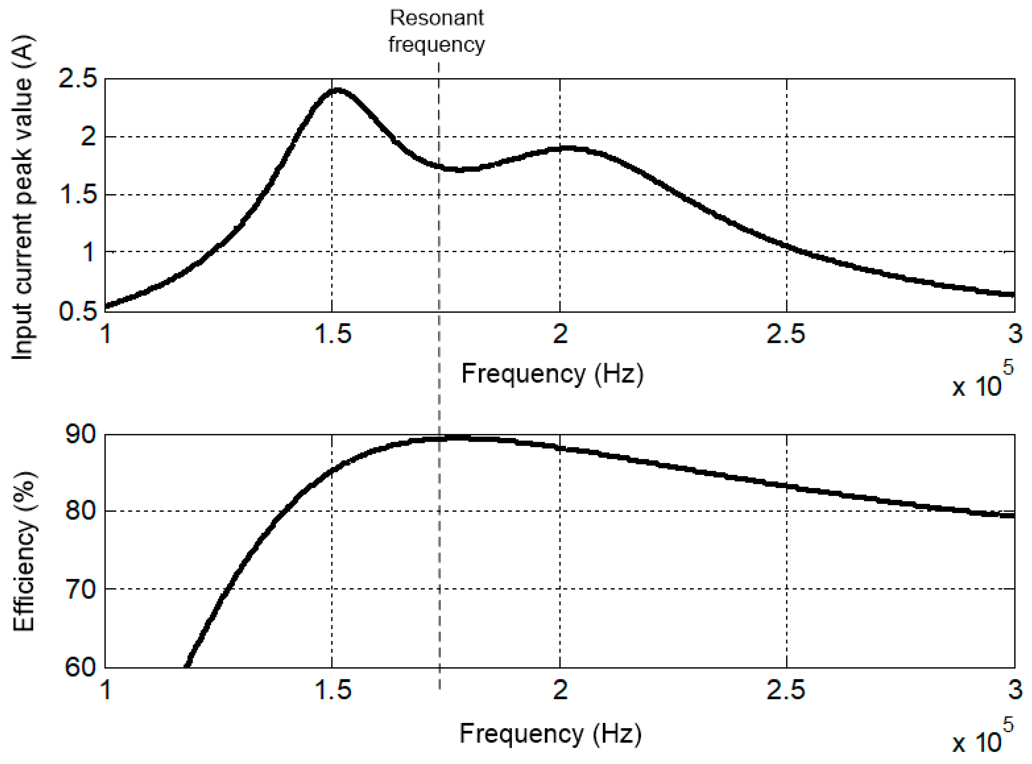
The presented study shows that due to the frequency characteristics of the resonant WPT system, conventional spread spectrum techniques may not give a considerable reduction in conducted emissions, because of the significant increase in the conducted emissions levels at the frequencies close to the frequencies at which the input current is maximum. Moreover, due to the fact that the losses depend on the frequency, the efficiency goes down as switching frequency significantly deviates from the resonant frequency. In order to improve the reduction in conducted emissions, a novel spread spectrum technique—the three-frequency and three-duty cycle (3F3D) technique—was proposed. The advantages of the proposed spread spectrum technique are: (1) due to more even distribution of the conducted emissions energy within the first-harmonic sidebands, it can give a better reduction in conducted emissions than conventional conducted emission reduction techniques; (2) a better efficiency of WPT system; (3) it is a simple approach because it can be implemented by using an inexpensive 8-bit microcontroller. In the novel spread spectrum technique, a better conducted emission reduction and efficiency are achieved by choosing lower values of duty cycles of the control signal at minimum and maximum switching frequencies.
The study presented may be useful for engineers and researchers who develop wireless power transfer systems with reduced conducted electromagnetic emissions.

