Abstract
The dimensioning of wireless power transfer systems requires compliance with safety standards for human exposure and electromagnetic compatibility. For this reason, shielding is conventionally carried out with heavy and costly plates. In order to evaluate a lightweight and low-cost alternative, this paper presents a comprehensive investigation of the shielding effectiveness of metal meshes in magnetic fields of wireless power transfer systems, including analytical modeling and experimental validation. Special emphasis is laid on the validation of novel analytical approximation approaches to model the anisotropic electrical conductivity of metal meshes. The proposed approaches show good consistency of the mean value taking into account warp and weft direction, whereas the modeling of the anisotropic behavior is not sufficiently accurately represented. Using the calculated electrical conductivity, the analytical modeling of the maximum shielding effectiveness based on a literature-known approach is very consistent for the experimental validation. Thus, the performed studies provide a significant contribution to the dimensioning of metal meshes as shielding for wireless power transfer systems.
1. Introduction
Wireless power transfer systems (WPTSs) are considered a promising technology to increase the acceptance of electric vehicles (EVs) [1,2], since WPTSs provide vehicle charging without user intervention. In order to charge electric vehicles, a transfer power of up to 11 kW is required. Thus, high magnetic field densities are necessary for wireless power transfer (WPT). However, magnetic fields must be compliant with the reference level of electromagnetic field (EMF) safety standards for human exposure and the electromagnetic compatibility (EMC) regulations to avoid disturbances in other electric or electronic devices [3]. Additionally, time-harmonic magnetic fields induce eddy currents in metallic parts close to WPTSs, resulting in power losses and local heating effects, which reduce the transfer efficiency of WPTSs. Thus, effective shielding is required to shield surrounding metallic parts and keep the EMF within certain limits.
The near-field shielding of automotive WPTSs is conventionally realized by using flat plates made of aluminum or copper due to their high electrical conductivity [3,4,5,6,7]. However, the utilization of such plates results in receiver modules with high stiffness, high weight and high costs. Alternatively, metal meshes provide mechanical flexibility and low weight in combination with high market accessibility and low costs. However, metallic fabrics are currently neither used nor elaborated for the purpose of shielding automotive WPTSs. As a result, the electromagnetic behavior of metal meshes in magnetic fields of automotive WPTSs is not determined yet. In order to dimension metal meshes for these applications, efficient approaches are required to calculate the electrical conductivity, which is the key material property for predicting the shielding effectiveness (SE) of the magnetic near-field. In this respect, analytical approaches are key, as there is no need for numerical simulation using finite elements, which are time-intensive and computationally costly.
In order to realize a system-integrated and lightweight shielding, this paper presents a comprehensive investigation of the SE of metal meshes in magnetic fields in the context of automotive WPTSs using analytics and experiments. Based on the study of related works provided in Section 2, a novel analytical approximation approach for calculating the electrical conductivity of metal meshes is presented in Section 3. On this basis, the SE of metal meshes is determined using a literature-known approach presented in Section 2. For the experimental validation, appropriate configurations of metal meshes for shielding automotive WPTSs are selected in Section 4. Moreover, the experimental setups to determine the electrical conductivity and shielding behavior of metal meshes in magnetic fields are detailed. In Section 5, the results of the analytical calculations are validated with the experimental measurements. On this basis, the prediction quality of the proposed analytical model is discussed. Moreover, quantitative comparisons between the investigated meshes enable the derivation of an adequate configuration for shielding magnetic fields of automotive WPTSs. Finally, Section 6 provides conclusions and future prospects.
2. Related Works
2.1. Shielding Strategies
Shielding strategies for WPTSs can be categorized into active and passive shielding. For active shielding, an additional reactive coil is used, requiring an additional power supply [8,9,10,11]. Such methods significantly increase the weight, size and overall complexity of WPTSs. For passive shielding, high-permeability materials are included for guiding the magnetic flux. Additionally, shielding with sufficiently high electrical conductivity can be exploited for field cancellation. Effective cancellation of the electromagnetic field is discussed in [12,13] using a combination of those two methods.
This paper focuses on the development of passive shielding for automotive WPTSs using electrically conductive materials. Due to the operating frequency of approx. 85 kHz, the near-field range of WPTSs for EVs is approx. 561 m. Therefore, the field calculation of WPTSs in the vicinity of an electric vehicle is assigned to the calculation of quasi-stationary magnetic fields. The shielding of these magnetic fields is based on the principle of the electrodynamic shield (EDS). Figure 1 schematically illustrates the principle of electrodynamic shielding.

Figure 1.
Principle of electrodynamic shielding in quasi-stationary magnetic fields of wireless power transfer systems according to [14]: (a) penetration of an external alternating magnetic field in an electrically conductive material with , (b) induction of an alternating electrical field , (c) eddy current induction, (d) distribution of the resulting magnetic field as a result of the internal counterfield .
According to Faraday’s law of induction, an alternating magnetic field induces eddy currents into an electrically conductive material (Figure 1a,b). According to Lenz’s law, the magnetic field created by the induced eddy currents counteracts the initial magnetic field (Figure 1c,d). The shielding effectiveness depends on the field properties and the material-specific skin depth :
where represents the electrical conductivity, is the magnetic permeability, and is the frequency of the magnetic field. Thus, a decrease in the skin depth results in increasing the shielding effectiveness.
2.2. Analytical Calculation
The analytical calculation of the SE in the near-field of WPTSs is based on a methodological approach considering an EDS with infinite lateral dimensions and a conductor loop carrying alternating current (AC) as given in Figure 2. The coil is oriented in a defined distance parallel to the EDS. Depending on the geometry and material properties of the EDS, as well as the frequency and intensity of the initial magnetic field with the magnetic field strength or flux density , a magnetic field with the strength or flux density is shielded by the EDS results. The shielding effectiveness of an EDS is defined as the logarithmic ratio of the shielded to the initial magnetic field [15]:
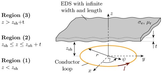
Figure 2.
Model of a plane plate as EDS with infinite lateral dimensions and a parallel-oriented coil according to [15,16,17].
The analytical solution to this problem can be differentiated into three methodological approaches [15]: the transmission-line model [18], the model of the equivalent circuit [19,20] and the exact solution to the boundary value problem [16,21]. The well-known transmission line model of Schelkunoff [18], describes the propagation of a plane wave through a shield by calculating its impedance under the consideration of reflection, transmission and re-reflection. The model of the equivalent circuit uses a circuit analog to simplify the calculation. This enables differentiation between low-impedance magnetic fields and high-impedance electric fields. However, the exact solution for electromagnetic field penetration into an ideal enclosure is possible by direct solution of the boundary value problem provided by Moser [21]. Furthermore, Feliziani et al. [17] adapted the transmission line model by using an equivalent circuit, enabling the calculation of SE in an axial and radial direction analogous to Moser [16]. In order to compare the approaches of Feliziani et al. [17] and Moser [16], an exemplary system configuration, as given in [17], is considered assuming a coil radius mm, an alternating current A and a transfer frequency kHz with a copper plate ( MS/m, ) of thickness mm. Figure 3 shows a comparison of the calculated shielding effectiveness along the radial distance x at depending on the distance between the coil and shield.
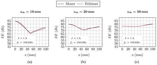
Figure 3.
Comparison of the approaches of Moser [16] and Feliziani et al. [17] using the example of a copper plate ( mm, MS/m, ) with the system parameters mm, A and kHz as given in [17]: Shielding effectiveness along the radial distance x at depending on the distance between coil and shield (a) mm, (b) mm and (c) mm.
The results given in Figure 3 show slight differences in the calculated SE at the distance mm. However, with increasing distance , the approaches yield nearly identical results. As the experimental validation of this paper uses a distance mm, the approach of Moser [16] is used for analytically calculating the shielding effectiveness of the investigated metal meshes in this paper. Since the detailed derivation of the formula work is shown in [16,21], only a brief summary is given herein.
According to Figure 2, the quasi-stationary field problem can be formulated separately for regions (1) and (2) by using the magnetic vector potential :
where is the repetency and represents the propagation coefficient of the medium. Using the method separation of variables [22] and the boundary conditions and , the magnetic vector potentials of the initial and shielded magnetic fields can be determined. Thus, the components of the resulting magnetic field vectors can be determined by using :
where and are the Bessel functions of the first kind. Furthermore, the parameters , and mit are applied. Thus, the shielding effectiveness is determined by:
However, with regard to the current research, the application of this literature-known approach to approximate the SE of metal meshes is still pending.
2.3. Metal Meshes
According to Figure 4, metal meshes are textile fabrics consisting of wires oriented in two main directions (warp and weft wires) that are usually crossed perpendicular to each other [23]. Depending on the way the wires are woven (weave), the properties of the resulting metal mesh can be designed according to the requirements. For maximum shielding effectiveness in the near-field of magnetic fields, the following requirements are to be taken into account [15,24]:
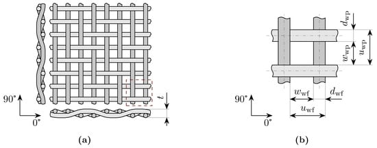
Figure 4.
Schematic representation of a metal wire mesh according to DIN ISO 9044 [25]: (a) Twill binding 2/2, (b) mesh size w, wire diameter d and pitch u.
- To ensure a sufficient SE, the wires need to be made of a material with high electrical conductivity .
- To ensure a sufficient SE, the open screen area must be sufficiently small (see Figure 4),where is the wire diameter in warp direction, is the wire diameter in weft direction, is the mesh size in warp direction and is the mesh size in weft direction.
- To ensure an unhindered formation of eddy currents, solid connections of the warp and weft wires need to be given at the undulation points.
However, research on the shielding effectiveness of metal meshes in magnetic fields of automotive wireless power transfer systems cannot be found in the literature. Table 1 summarizes relevant research on the SE of metal meshes.

Table 1.
Overview of existing research on the shielding effectiveness of metal wire mesh.
As shown in Table 1, several authors studied the shielding behavior and effectiveness of metal meshes in far-field, taking into account plane waves with high frequencies. Most of these studies focused on the analytical calculation of the shielding effectiveness using the well-known approach of Schelkunoff [18] combined with experimental validation, as given in [28,32,33,35,36,38]. Regarding far-field, only a few studies [33,34,35,37] present numerical simulations for the prediction of the shielding behavior of metal meshes. In near-field, only a few authors investigated the SE of metal meshes [38,39,40,41]. In this respect, the works of Criel et al. [38] and Rong et al. [40] focus on the analytical modeling of metal meshes. However, these works are based on far-field approaches to determine the near-field SE, which results in significant discrepancies between analytic approaches and simulation. Moreover, none of the literature-known studies considered transfer frequencies of WPTSs, according to Table 1. Furthermore, experimental validation of the near-field SE of metal meshes cannot be found in the literature.
3. Analytical Approach for Modeling the Electrical Conductivity of Metal Meshes
According to the study of the current state-of-the-art given in Section 2, analytical approaches for predicting the SE of WPTSs for EVs are required for dimensionally adequate metal meshes in a time- and cost-effective way. In this context, the analytical calculation of the electrical conductivity is key, as increasing this material parameter results in an increase in SE. To address this, the following section presents a novel analytical approach to approximate the specific electrical conductivity or the specific resistivity :
where is the ohmic resistance, is the cross-sectional area and is the length of the metal mesh in a specific direction . Thus, under the assumption of given mesh dimensions, the specific resistance is a function of the ohmic resistance , which can be approximated analytically using a simplified impedance model illustrated in Figure 5.
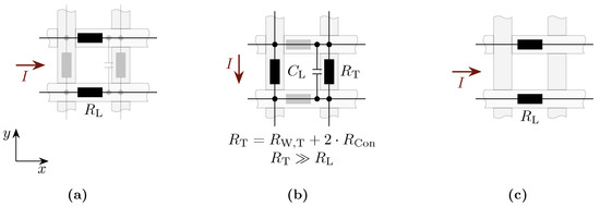
Figure 5.
Impedance model for determining the electrical resistivity or the electrical conductivity of metallic wire mesh: (a) Impedance model in the longitudinal direction, (b) impedance model in the transverse direction and (c) simplified impedance model for the analytical calculation.
Regardless of the weave, the electrical conductivity of metal meshes differs in longitudinal and transverse directions. In the longitudinal direction, the conduction of the electric current I is described in the direction of the impressed current. In the transverse direction, the electric current I is conducted perpendicular to the impressed current flow. The longitudinal conduction of metallic meshes is characterized by the ohmic wire resistance and the number of wires in the direction of the impressed current (see Figure 5a). The transverse conduction is primarily determined by the specific electrical wire resistance and the number of wires perpendicular to the direction of the impressed current as well as the ohmic resistances of the contacting at the undulation points between warp and weft wire (see Figure 5b). Depending on the mesh size, the resulting capacities must be taken into account. However, in the frequency range of automotive WPTSs, capacitive coupling is negligible. Moreover, it can be assumed that the ohmic contact resistance is significantly higher than the wire resistance . Thus, the longitudinal conduction is dominant under the assumption of identical material-specific electrical conductivities of warp and weft wires. As a result, solely the ohmic wire resistance in the longitudinal direction and the number of wires N are taken into account for the analytical calculation of the anisotropic resistance of metal meshes (see Figure 5c):
Accordingly, the anisotropic ohmic resistance results from the parallel arrangement of the ohmic wire resistance in the direction of the impressed current flow I taking into account the specific electrical conductivity of the wire material , the wire cross-section and the crimp of the mesh . Under the premise of the given wire material and mesh dimensions, the calculation of the anisotropic volume resistance or specific electrical conductivity of metal meshes results in a function of the wire length , which is independent of the number of undulations considering the repetition of the unit wave cells. Thus, the wire length can be analytically approximated with linear, trigonometric [42] or combined approaches, taking into account pre-stretching in the warp direction due to the extraction of warp wires in weaving processes. Figure 6 summarizes the approaches and formula work for analytically calculating the wire length of meshes with plain and twill weave 2/2 in the warp direction. These approaches are equally applicable to the calculation of the wire length in the weft direction.
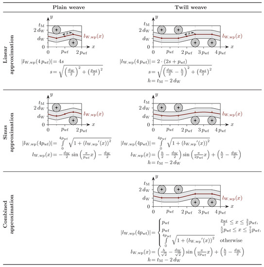
Figure 6.
Approximation approaches for calculating the wire length in the warp direction for meshes with plain and twill weave 2/2 with and .
4. Experimental Validation
The experimental validation of the proposed analytical approach is executed on appropriate metal meshes, which were selected taking the requirements given in Section 2 into account. Due to the functional relationship of SE and electrical conductivity, the experimental validation of this paper is divided into 2 steps: 1. determination of electrical conductivity, 2. determination of shielding effectiveness. The experimental procedures and the setups are based on modifications of the setups given in [14,43], which were used for the experimental investigation of the electrical conductivity and the SE of carbon fiber-reinforced plastics (CFRP). The following section presents the modified setups for the determination of electrical conductivity and SE of metal meshes.
4.1. Materials
Table 2 summarizes the metal meshes and the respective characteristics, which were examined in this paper. As postulated, the SE increases with lower skin depths. According to (1), the skin depth decreases with the higher electrical conductivity of the EDS. Therefore, metal meshes made of copper (Cu-ETP [44]) and aluminum (AlMg3 [45]) wires were selected. The cross-sections of the wires () investigated in this paper were defined under the premise of a sufficient material thickness () compared to the material-specific skin depth at a transfer frequency kHz according to (1). In order to examine the influence of the open screen area on SE, metal meshes with plain and twill weave were investigated. Due to the lower degree of undulation compared to meshes with plain weave, twill weaves provide minimal mesh sizes and improved contacting between warp and weft wires. However, decreasing mesh size increases mass per unit area according to Table 2. In addition to configurations with square mesh size (), metal meshes with rectangular mesh scaled by two in the 90-direction () were examined.

Table 2.
Parameters of the investigated metal mesh according to DIN ISO 9044 [25].
4.2. Electrical Conductivity
The electrical resistance of metal meshes are to be expected in the m-range. Thus, electrical resistances of metal meshes are to be measured using a four-wire system according to DIN IEC 468 [46]. Therefore, a modification of the test system used in [14] was carried out. The modified test setup enables measurements based on the two-wire system and four-wire system due to modular construction. Figure 7 illustrates the modified experimental setup for determining the electrical conductivity of metal meshes.
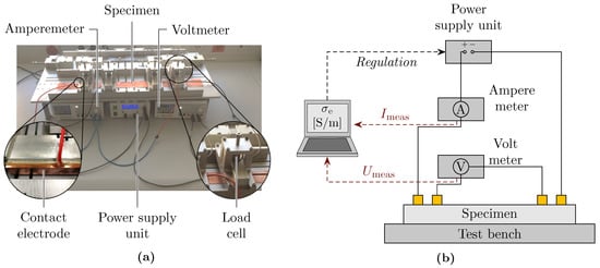
Figure 7.
Experimental setup for the determination of the electrical conductivity of metal meshes: (a) photography and (b) schematic representation.
In order to ensure a reproducible determination of the electrical resistance , electrical contact of the test specimens with uniform current density distribution over the electrode interface and uniform contact pressure is required. Due to the resulting line contacting, the setup provides circular cross-sections of the contact electrodes for the measurements. The contact force is defined at 1 kN, and the settling time is defined at 60 s.
The experimental investigations include the determination of the electrical resistance or the electrical conductivity of the metal meshes given in Table 2 in the angular dimensions and . Although the specific electrical resistance is not a function of the test specimen length, the test specimen must fully cover the contact electrodes for current feeding. Thus, the measurements were made on rectangular test specimens with a width mm and a length mm. The distance of the electrodes to the current feed is dimensioned to mm. Regardless of material orientation, the current is set to A. Knowing the measured voltage , the ohmic resistance and the specific electrical conductivity can be determined:
Experimental measurements were made by using three test specimens of each configuration and angular position. The validation of the measurement accuracy of the test system was carried out on standardized specimens made of copper with known conductivity MS/m. The mean relative deviations between the analytically determined and measured specific electrical conductivities of these reference samples are less than 1%. Thus, sufficient measurement accuracy is given to determine the specific electrical conductivity of copper specimens.
4.3. Shielding Effectiveness
Figure 8 schematically shows the experimental setup for investigating the SE of metal meshes. According to [43], a square test specimen measured to the dimensions of 1000 × 1000 mm is positioned at a defined distance of mm above the transmitting coil. The coil is realized in a circular design with an outer diameter of 500 mm using three turns consisting of two high-frequency (HF) litz wires connected in parallel with a number of 840 wires of 0.1 mm diameter each. To detect the local magnetic field, a spherical magnetic field probe of the type Hioki FT 3470 100 cm2 is located at a defined distance of mm above the test bench carrying the specimen. For lateral positioning, the field probe is mounted on a slide enabling longitudinal movement. In total, seven measuring points are defined along the longitudinal direction at a distance of mm each, with the first point located above the center of the transmitter coil. The current control of the test system is computer-aided via power electronics. The field frequency and the coil current are determined via an oscilloscope of type Agilent DS05014A. Based on SAE J2954 [3], the transfer frequency of the initial magnetic field is defined at 85 kHz. The coil current is set to 60 A.

Figure 8.
Experimental setup for the determination of the shielding effectiveness of metal meshes.
5. Results and Discussion
5.1. Electrical Conductivity
Figure 9 summarizes the results of the analytical calculation and experimental determination of the specific electrical conductivity in the directions of and . In addition to the specific electrical conductivity, the mean of and are shown, as the analytical calculation of the SE only takes into account the mean value.
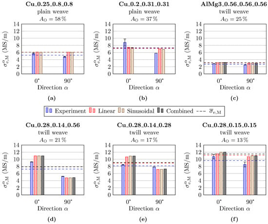
Figure 9.
Comparison of the measured and analytically calculated specific electrical conductivity of the investigated meshes depending on the direction : (a) Cu_0.25_0.8_0.8, (b) Cu_0.2_0.31_0.31, (c) AlMg3_0.56_0.56_0.56, (d) Cu_0.28_0.14_0.56, (e) Cu_0.28_0.14_0.28 and (f) Cu_0.28_0.14_0.14.
As expected, the measurements show that a decrease in open screen area results in increasing the electrical conductivity, as the electrical resistance decreases when the number of wires with identical wire material is increased. Regardless of the configuration, the experimental results show a significant anisotropy of the electrical conductivity in the warp ( = 0) and weft ( = 90) directions, as the electrical conductivity in the 0-direction is always higher than in the 90-direction. This is expected due to the pre-stretching of warp wires in the weaving process. With regard to meshes with rectangular mesh sizes, the different number of wires in warp and weft directions reinforces the anisotropic behavior.
With respect to the analytical calculations, only small deviations are determined comparing the proposed approximation approaches. Regardless of the configuration and orientation, the calculated electrical conductivity deviates less than 1% comparing the linear, sinusoidal and combined approximation approaches. Compared to the experimental results, the anisotropic behavior of the electrical conductivity in warp and weft directions is not sufficiently mapped, as the experimental results show greater deviations in the 0-direction and 90-direction compared to the analytically calculated quantities. As a result, the relative deviation between analytical calculation and the measurements is up to 30% depending on the configuration and orientation of the investigated meshes. For meshes with square mesh size, the relative deviation in the 0-direction is significantly smaller compared to the 90-direction, while this effect is reversed for meshes with rectangular mesh size. This can be explained by the constitution of the investigated metal meshes. Meshes with a mesh size significantly higher than the wire diameter have less crimp compared to meshes with a mesh size smaller than the diameter. As a result, the cross-sectional deformation of the warp wire caused by crimp is smaller for meshes with small mesh sizes. In this respect, the assumption of constant cross-sections along the entire length used for analytical approximation is considered valid. Concurrently, large mesh sizes enable greater pre-stretching of the warp wires, which results in a higher undulation of the weft wires. In this regard, the analytical approximation approaches assume contact between the warp and weft wires at the undulation point. In reality, the weft wires may separate from the warp wires at the undulation points due to the limited deformation capacity. Thus, this effect is not represented by the proposed approximation approaches.
Decreasing the mesh size results in higher crimp and deformation of the warp wires. In particular, meshes with a mesh size less than the wire diameter can only be produced using twill weave, resulting in three-dimensional displacements and large cross-sectional deformations of the undulated wires. As a consequence, this effect leads to variable mesh sizes. Thus the assumption of constant mesh sizes used for the proposed analytical approximation is not valid for this type of metal mesh. Therefore, it can be concluded that microscopic analysis of the mesh structure is required to determine the cross-sectional deformation and the variability of the mesh sizes to improve the accuracy of the proposed approximation approaches. In the case of rectangular meshes, the reduction of electrical conductivity in the 90-direction compared with the 0-direction is primarily characterized by the reduced number of weft wires. Geometric effects are thus of minor relevance. Consequently, analytical approximation works sufficiently well in the 90-direction. In the 0-direction, the geometric effects dominate, increasing the discrepancy between the analytical calculations and the measurements.
However, calculating the SE of metal meshes only requires the mean value of the specific electrical conductivity for the directions and . In the comparison of analytical approximation and experiments, the relative deviation is a maximum of 15%. For this reason, sufficient accuracy of the proposed approximation approaches for the calculation of the SE is expected. In this regard, the use of the proposed linear approximation approach is advised due to the reduced complexity compared with the sinusoidal and combined approximation approach.
5.2. Shielding Effectiveness
Figure 10 summarizes the results of the analytical calculation using the approach of Moser [16] and experimental determination of the shielding effectiveness . The SE of the investigated metal meshes is determined on the basis of both the experimentally determined mean value of the electrical conductivity and the analytically approximated mean value of the electrical conductivity using the proposed linear approximation approach.
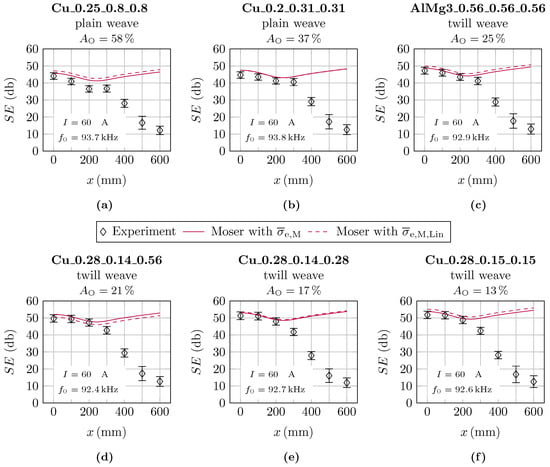
Figure 10.
Comparison of the measured and analytically calculated shielding effectiveness based on the mean specific electrical conductivity determined by the experiment and calculated by the proposed linear approximation: (a) Cu_0.25_0.8_0.8, (b) Cu_0.2_0.31_0.31, (c) AlMg3_0.56_0.56_0.56, (d) Cu_0.28_0.14_0.56, (e) Cu_0.28_0.14_0.28 and (f) Cu_0.28_0.14_0.14.
Regardless of the investigated configuration, the experimental results show the highest SE above the center of the transmitter coil. The SE decreases with increased lateral distance to the coil center. This is expected due to the limited dimensions of the metal meshes, resulting in a dominant z-component of the magnetic field at the coil center, while the -component gains dominance towards the edges of the specimen. Moreover, the magnetic counterfield caused by the shield influences the inductance of the transmitter coil, thus changing the resonant frequency of the driving series resonant tank, resulting in a different transfer frequency compared to the initial frequency, kHz, of the magnetic field without shielding.
As expected, in alignment with the determined electrical conductivity, the measurements show that a decrease in the open screen area results in increasing the SE. In particular, the shielding of the dominant z-component of the magnetic field above the transmitting coil is improved with smaller mesh sizes as the eddy current induction increases, resulting in a higher intensity of the magnetic counterfield. Conspicuously, the SE of the specimen based on wires made of AlMg3 is in the same order of magnitude as the other specimens made of copper, although the measured electrical conductivity is significantly lower. Thus, it can be concluded that the open screen area and the thickness dominantly influence the SE of metal meshes.
Compared to the experimental results, the analytically calculated SE using the approach of Moser [16] maps the shielding behavior very well up to a radial distance of the outer coil radius, mm, taking into account the measuring tolerance of the magnetic field probe. Up to the lateral distance of mm, the maximum relative deviation is 4%, taking into account the mean value of the measured electrical conductivity . Using the mean value of the analytically calculated electrical conductivity based on the proposed linear approximation approach, the relative deviation increases by up to 7%. Considering lateral distances , the approach of Moser [16] is no longer valid for this experimental setup due to the assumption of a shield with infinite lateral dimensions. However, in conclusion, the presented analytical approaches are considered as valid to predict the maximum shielding effectiveness of metal meshes with finite dimensions.
6. Conclusions
This paper presents a comprehensive study of the shielding effectiveness of metal meshes, comparing analytical approaches and experiments. Due to the significance of the shielding effectiveness, special emphasis was given to the analytical and experimental determination of the electrical conductivity of metal meshes. For this purpose, an approximation approach for analytically calculating the electrical conductivity of metal meshes is introduced based on linear, sinusoidal and combined approximations of the wire length. Regardless of the weave and orientation, the analytically calculated electrical conductivity deviates less than 1%. Due to the reduced complexity compared to the sinusoidal and combined approximation approach, the linear approximation is advantageous. The experimental measurements using a four-wire system show a relative deviation in the range of up to , which is highly dependent on the configuration and orientation of the investigated meshes. This can be explained by geometric effects caused by weaving, which are not sufficiently represented by the proposed approximation approaches. To improve the accuracy of the approximation, a microscopic analysis of the mesh structure is required. However, calculating the shielding effectiveness of metal meshes solely requires the mean value of the electrical conductivity in the 0-direction and the 90-direction, which shows a maximum deviation of 15% from the experimental results. Based on the analytically calculated electrical conductivities, the analytical calculation of the shielding effectiveness using the approach of Moser [16] maps the shielding behavior very well up to a radial distance of the outer coil radius compared to the experimental results. Considering lateral distances higher than the outer coil radius, the approach of Moser [16] is no longer valid due to the assumption of infinite shielding. However, the presented analytical approaches are valid for predicting the maximum shielding effectiveness of metal meshes with finite dimensions. Thus, the performed studies contribute significantly to the dimensioning of metal meshes as shielding for wireless power transfer systems using analytical approaches without having to perform time-consuming and computationally intensive numerical simulations. However, the presented investigations are limited to metal meshes with a maximum open screen area of . Meshes with a bigger open screen area might cause a divergent shielding behavior due to additional geometric effects. Since the approach of Moser [16] assumes a shielding with homogenized material properties, the analytical calculation may no longer be valid. This study is considered an object for future works.
Author Contributions
The authors contributed to this work by collaboration. Modeling, S.Z.; validation, S.Z. and M.H.; writing—review and editing, A.W.; supervision, N.M. All authors have read and agreed to the published version of the manuscript.
Funding
This research received no external funding.
Institutional Review Board Statement
Not applicable.
Informed Consent Statement
Not applicable.
Data Availability Statement
Not applicable.
Conflicts of Interest
The authors declare no conflict of interest.
Abbreviations
The following abbreviations are used in this manuscript:
| AC | Alternating current |
| CFRP | Carbon fiber reinforced plastics |
| EDS | Electrodynamic shield |
| EMC | Electromagnetic compatibility |
| EMF | Electromagnetic field |
| HF | High-frequency |
| SE | Shielding effectiveness |
| WPTS | Wireless power transfer |
| WPTSs | Wireless power transfer systems |
References
- Fett, D.; Ensslen, A.; Jochem, P.; Fichtner, W. A Survey on User Acceptance of Wireless Electric Vehicle Charging. World Electr. Veh. J. 2018, 9, 36. [Google Scholar] [CrossRef]
- Khutwad, S.R.; Gaur, S. Wireless charging system for electric vehicle. In Proceedings of the 2016 International Conference on Signal Processing, Communication, Power and Embedded System (SCOPES), Paralakhemundi, India, 3–5 October 2016; pp. 441–445. [Google Scholar] [CrossRef]
- SAE Society of Automotive Engineers. (R) Wireless Power Transfer for Light-Duty Plug-In/Electric Vehicles and Alignment Methodology; SAE Society of Automotive Engineers: Warrendale, PA, USA, 2019. [Google Scholar]
- Zhou, J.; Gao, Y.; Zhou, C.; Ma, J.; Huang, X.; Fang, Y. Optimal power transfer with aluminum shielding for wireless power transfer systems. In Proceedings of the 2017 20th International Conference on Electrical Machines and Systems (ICEMS), Sydney, NSW, Australia, 11–14 August 2017; pp. 1–4. [Google Scholar] [CrossRef]
- Songcen, W.; Bin, W.; Xiaokang, W.; Chong, X.; Jinxing, X.; Weimei, G.; Jiaqi, X. Electromagnetic shielding design for magnetic coupler of N-type dynamic electric vehicle wireless power transfer systems. In Proceedings of the 2019 22nd International Conference on Electrical Machines and Systems (ICEMS), Harbin, China, 11–14 August 2019; pp. 1–7. [Google Scholar] [CrossRef]
- Zimmer, S.; Rothenberg, S.; Tattko, B.; Baumer, T.; Baier, K.; Glöggler, C.; Winkler, A.; Modler, N. Vehicle Integration of wireless power transfer systems: An experimental safety investigation of underfloor impact scenarios. In Proceedings of the 31th International Electric Vehicle Symposium & Exhibition (EVS31), Kobe, Japan, 30 September–3 October 2018. [Google Scholar]
- Onar, O.C.; Campbell, S.L.; Seiber, L.E.; White, C.P.; Chinthavali, M. Vehicular integration of wireless power transfer systems and hardware interoperability case studies. In Proceedings of the IEEE Energy Conversion Congress, Milwaukee, WI, USA, 18–22 September 2016; pp. 1–8. [Google Scholar] [CrossRef]
- Kim, J.; Kim, J.; Kong, S.; Kim, H.; Suh, I.S.; Suh, N.P.; Cho, D.H.; Kim, J.; Ahn, S. Coil Design and Shielding Methods for a Magnetic Resonant Wireless Power Transfer System. Proc. IEEE 2013, 101, 1332–1342. [Google Scholar] [CrossRef]
- Kim, S.; Park, H.H.; Kim, J.; Kim, J.; Ahn, S. Design and Analysis of a Resonant Reactive Shield for a Wireless Power Electric Vehicle. IEEE Trans. Microw. Theory Tech. 2014, 62, 1057–1066. [Google Scholar] [CrossRef]
- Choi, S.Y.; Gu, B.W.; Lee, S.W.; Lee, W.Y.; Huh, J.; Rim, C.T. Generalized Active EMF Cancel Methods for Wireless Electric Vehicles. IEEE Trans. Power Electron. 2014, 29, 5770–5783. [Google Scholar] [CrossRef]
- Campi, T.; Cruciani, S.; Maradei, F.; Feliziani, M. Active Coil System for Magnetic Field Reduction in an Automotive Wireless Power Transfer System. In Proceedings of the 2019 IEEE International Symposium on Electromagnetic Compatibility, Signal & Power Integrity (EMC+SIPI), New Orleans, LA, USA, 22–26 July 2019; pp. 189–192. [Google Scholar] [CrossRef]
- Kim, H.; Cho, J.; Ahn, S.; Kim, J.; Kim, J. Suppression of leakage magnetic field from a wireless power transfer system using ferrimagnetic material and metallic shielding. In Proceedings of the 2012 IEEE International Symposium on Electromagnetic Compatibility, Pittsburgh, PA, USA, 6–10 August 2012; pp. 640–645. [Google Scholar] [CrossRef]
- Feliziani, M.; Cruciani, S. Mitigation of the magnetic field generated by a wireless power transfer (WPT) system without reducing the WPT efficiency. In Proceedings of the International Symposium on Electromagnetic Compatibility (EMC Europe), Brugge, Belgium, 2–6 September 2013; IEEE: Piscataway, NJ, USA, 2013. [Google Scholar]
- Holzer, M. On the shielding properties of carbon fiber reinforced plastic composites in magnetic near fields with low kilohertz frequency. In SAMPE Converence Proceedings, Proceedings of the Sampe 2016, Long Beach, CA, USA, 23–26 May 2016; Society for the Advancement of Material and Process Engineering: Covina, CA, USA, 2016. [Google Scholar]
- Celozzi, S.; Araneo, R.; Lovat, G. Electromagnetic Shielding; Wiley series in microwave and optical engineering; Wiley-Interscience IEEE Press: Hoboken, NJ, USA; IEEE Xplore: Piscataway, NJ, USA, 2008. [Google Scholar]
- Moser, J.R. Low-frequency low-impedance electromagnetic shielding. IEEE Trans. Electromagn. Compat. 1988, 30, 202–210. [Google Scholar] [CrossRef]
- Feliziani, M.; Cruciani, S.; Campi, T.; Maradei, F. Near field shielding of a wireless power transfer (wpt) current coil. Prog. Electromagn. Res. 2017, 77, 39–48. [Google Scholar] [CrossRef][Green Version]
- Schelkunoff, S.A. The Impedance Concept and Its Application to Problems of Reflection, Refraction, Shielding and Power Absorption. Bell Syst. Tech. J. 1938, 17, 17–48. [Google Scholar] [CrossRef]
- Bridges, J.E. An update on the circuit approach to calculate shielding effectiveness. IEEE Trans. Electromagn. Compat. 1988, 30, 211–221. [Google Scholar] [CrossRef]
- Miller, D.; Bridges, J. Review of Circuit Approach to Calculate Shielding Effectiveness. IEEE Trans. Electromagn. Compat. 1968, EMC-10, 52–62. [Google Scholar] [CrossRef]
- Moser, J.R. Low-Frequency Shielding of a Circular Loop Electromagnetic Field Source. IEEE Trans. Electromagn. Compat. 1967, 9, 6–18. [Google Scholar] [CrossRef]
- Papula, L. Mathematik für Ingenieure und Naturwissenschaftler: Ein Lehr- und Arbeitsbuch für das Grundstudium; Lehrbuch, Springer Vieweg: Wiesbaden, Germany, 2014. [Google Scholar]
- Cherif, C. Textile Werkstoffe für den Leichtbau: Techniken-Verfahren-Materialien-Eigenschaften; Springer: Berlin/Heidelberg, Germany, 2011. [Google Scholar]
- Burton, P.C. Joining of two technologies: Wire mesh and plastic to produce shielded plastic enclosures. In Proceedings of the 1999 IEEE International Symposium on Electromagnetic Compatability. Symposium Record (Cat. No.99CH36261), Seattle, WA, USA, 2–6 August 1999; pp. 586–589. [Google Scholar] [CrossRef]
- DIN ISO 9044; DIN Deutsches Institut für Normung e.V. Industriedrahtgewebe-Technische Anforderungen und Prüfung. ISO: Geneva, Switzerland, 2017.
- Liu, L.F.; Zhang, Q.S. Analysis of Electromagnetic Shielding Effectiveness of Metal Material. Adv. Mater. Res. 2012, 538–541, 655–659. [Google Scholar] [CrossRef]
- Dharma Raj, C.; Ramyasree, M.V.S.L.; Sravan Kumar, V. Analysis of wire mesh screen for shielding effectiveness in different frequency ranges. In Proceedings of the 2011 International Conference on Computer, Communication and Electrical Technology (ICCCET), Tirunelveli, India, 18–19 March 2011; pp. 198–203. [Google Scholar] [CrossRef]
- Wang, L.B.; See, K.Y.; Chang, W.Y.; Lu, C.W.; Ng, S.T. Electromagnetic shielding analysis of printed flexible meshed screens. In Proceedings of the 2010 Asia-Pacific International Symposium on Electromagnetic Compatibility, Beijing, China, 12–16 April 2010; pp. 965–968. [Google Scholar] [CrossRef]
- Bulut, F.; Efendioglu, H.S.; Solak, V.; Yabuloglu, M.; Ozer, H. Electromagnetic shielding behavior of different metallic wire-meshes and thin metal plate. In Proceedings of the 2017 IV International Electromagnetic Compatibility Conference (EMC Turkiye), Ankara, Turkey, 24–27 September 2017; pp. 1–3. [Google Scholar] [CrossRef]
- Casey, K.F. Electromagnetic shielding behavior of wire-mesh screens. IEEE Trans. Electromagn. Compat. 1988, 30, 298–306. [Google Scholar] [CrossRef]
- Dichen, L.; Suqiao, D. The study of metal meshes on electromagnetic interference shielding effectiveness. In Proceedings of the Asia-Pacific Conference on Environmental Electromagnetics. CEEM’2000 (IEEE Cat. No.00EX402), Shanghai, China, 7 May 2000; Beijing Univ. Posts & Telecommun. Press: Beijing, China, 2000; pp. 326–332. [Google Scholar] [CrossRef]
- Sarto, M.S.; Greco, S.; Tamburrano, A. Shielding Effectiveness of Protective Metallic Wire Meshes: EM Modeling and Validation. IEEE Trans. Electromagn. Compat. 2014, 56, 615–621. [Google Scholar] [CrossRef]
- Mansson, D.; Ellgardt, A. Comparing analytical and numerical calculations of shielding effectiveness of planar metallic meshes with measurements in cascaded reverberation chambers. Prog. Electromagn. Res. 2012, 31, 123–135. [Google Scholar] [CrossRef][Green Version]
- Xu, P.; Di, Y.; Yao, X.; Yang, S. Study on Shielding Effectiveness of Metal Shielding Mesh of Cable Joint. In Proceedings of the 2020 6th Global Electromagnetic Compatibility Conference (GEMCCON), Xi’an, China, 20–23 October 2020; pp. 1–4. [Google Scholar] [CrossRef]
- Mariani Primiani, V.; Moglie, F.; Pastore, A.P. Field Penetration Through a Wire Mesh Screen Excited by a Reverberation Chamber Field: FDTD Analysis and Experiments. IEEE Trans. Electromagn. Compat. 2009, 51, 883–891. [Google Scholar] [CrossRef]
- Hyun, S.Y.; Jung, I.; Hong, I.P.; Jung, C.; Kim, E.J.; Yook, J.G. Modified Sheet Inductance of Wire Mesh Using Effective Wire Spacing. IEEE Trans. Electromagn. Compat. 2016, 58, 911–914. [Google Scholar] [CrossRef]
- Pramanick, M.; Pal, J.; Chakraborty, M.; Rahim, S.M.; Dey, T.K. Performance of single and double layered wire mesh electromagnetic shield(s) in the laboratories of degree engineering colleges. In Proceedings of the 2018 15th International Conference on ElectroMagnetic Interference & Compatibility (INCEMIC), Bengaluru, India, 13–16 November 2018; pp. 1–4. [Google Scholar] [CrossRef]
- Criel, S.; Martens, L.; de Zutter, D. Near- and far-field characterization of perforated screens: Theoretical and experimental study of proposed definitions for the shielding performance. In Proceedings of the IEEE Symposium on Electromagnetic Compatibility, Chicago, IL, USA, 22–26 August 1994; pp. 298–302. [Google Scholar] [CrossRef]
- Hashiba, J.; Kawajiri, T.; Shibuya, R.; Ishikuro, H. Shield effects of metal plate and mesh in wireless power delivery system. In Proceedings of the 2015 IEEE International Symposium on Radio-Frequency Integration Technology (RFIT), Sendai, Japan, 26–28 August 2015; pp. 235–237. [Google Scholar] [CrossRef]
- Rong, C.; Tao, X.; Lu, C.; Liu, M. Investigation of Magnetic Field Shielding by Mesh Aluminum Sheet in Wireless Power Transfer System. In Proceedings of the 2019 IEEE Wireless Power Transfer Conference (WPTC), London, UK, 18–21 June 2019; pp. 126–129. [Google Scholar] [CrossRef]
- Briki, I.; Pichon, L.; Ben Hadj Slama, J. Shielding Effectiveness of Perforated Screens Through an Inverse Problem-Based Resolution. IEEE Trans. Magn. 2016, 52, 1–4. [Google Scholar] [CrossRef]
- Romano, M. Charakterisierung von Gewebeverstärkten Einzellagen aus Kohlenstofaserverstärktem Kunststo (CFK) Mit Hilfe Einer Mesomechanischen Kinematik Sowie Strukturdynamischen Versuchen. Ph.D. Thesis, Universität der Bundeswehr München, München, Germany, 2016. [Google Scholar]
- Holzer, M. Beschreibung des Schirmverhaltens von kOhlenstofffaserverstärkten Kunststoffen in Magnetischen Wechselfeldern Automobiler Induktiver Ladesysteme. Ph.D. Thesis, Universität Stuttgart, Stuttgart, Germany, 2018. [Google Scholar]
- Deutsches Kupferinstitut. Cu-ETP, Düsseldorf, Germany. 2018. Available online: https://www.kupferinstitut.de/wp-content/uploads/2019/11/Cu-ETP.pdf (accessed on 31 May 2022).
- thyssenkrupp Materials Services GmbH. Material Data Sheet: Aluminium Alloy. Essen, Germany. 2017. Available online: https://ucpcdn.thyssenkrupp.com/_legacy/UCPthyssenkruppBAMXUK/assets.files/material-data-sheets/aluminium/5754.pdf (accessed on 31 May 2022).
- Deutsches Institut für Normung e.V. Verfahren zur Messung des Spezifischen (Elektrischen) Widerstandes Metallischer Werkstoffe; Beuth Verlag GmbH: Berlin, Germany, 1974.
Publisher’s Note: MDPI stays neutral with regard to jurisdictional claims in published maps and institutional affiliations. |
© 2022 by the authors. Licensee MDPI, Basel, Switzerland. This article is an open access article distributed under the terms and conditions of the Creative Commons Attribution (CC BY) license (https://creativecommons.org/licenses/by/4.0/).