Article

Intelligent Sensors and Environment Driven Biological Comfort Control Based Smart Energy Consumption System

1
Department of Electrical and Computer Engineering, COMSATS University Islamabad, Abbottabad Campus, Abbottabad 22060, Pakistan
2
School of Computing and Communications, Lancaster University, Bailrigg, Lancaster LA1 4YW, UK
3
Department of Electrical and Computer Engineering, COMSATS University Islamabad, Lahore Campus, Lahore 54700, Pakistan
4
Department of Electrical Engineering, UMT Lahore, Sialkot Campus, Sialkot 51310, Pakistan
5
Department of Electrical Engineering, Computer Engineering and Informatics, Cyprus University of Technology, Limassol 3025, Cyprus
*
Authors to whom correspondence should be addressed.
Electronics 2022, 11(16), 2622; https://doi.org/10.3390/electronics11162622
Submission received: 10 June 2022 / Revised: 16 August 2022 / Accepted: 19 August 2022 / Published: 21 August 2022

Abstract

:
The smart energy consumption of any household, maintaining the thermal comfort level of the occupant, is of great interest. Sensors and Internet-of-Things (IoT)-based intelligent hardware setups control the home appliances intelligently and ensure smart energy consumption, considering environment parameters. However, the effects of environment-driven consumer body dynamics on energy consumption, considering consumer comfort level, need to be addressed. Therefore, an Energy Management System (EMS) is modeled, designed, and analyzed with hybrid inputs, namely environmental perturbations, and consumer body biological shifts, such as blood flows in skin, fat, muscle, and core layers (affecting consumer comfort through blood-driven-sensations). In this regard, our work incorporates 69 Multi-Node (MN) Stolwijik’s consumer body interfaced with an indoor (room) electrical system capable of mutual interactions exchange from room environmental parameters and consumer body dynamics. The mutual energy transactions are controlled with classical PID and Adaptive Neuro-Fuzzy-Type II (NF-II) systems inside the room dimensions. Further, consumer comfort, room environment, and energy consumption relations with bidirectional control are demonstrated, analyzed, and tested in MATLAB/Simulink to reduce energy consumption and energy cost. Finally, six different cases are considered in simulation settings and for performance validation, one case is validated as real-time hardware experimentation.

1. Introduction

Smart grids are characterized as next generation power systems in which the use and need of information sharing and communication technology in electric power generation, transmission, distribution, and consumption are increasing with every passing day. In smart grids, the flow of electricity and information is a two-way process that facilitates the utilities and customers to share real-time information, such as electricity usage and electricity price through the deployment of smart meters [1]. Consequently, an efficient energy management technique must be employed within the home premises to minimize energy consumption costs, while maintaining the comfort level of the customers. Residential homes constitute a large percentage of electricity consumers. For instance, in the USA, they consume 40% of the total energy demand [2]. Therefore, a pressing need is to develop a cost-effective and intelligent energy management system for residential homes. A good two-way strategy for smart home energy management systems is to reduce energy consumption demand by rescheduling home appliances while the task for grid policymakers is to offer cost incentives to the customers for shift/reduce load demand. This two-way of practicing energy systems is a key area of research in energy systems modeling analysis, design, management, and control with consumer comfort and consumer satisfaction at the highest priority [3].
Recently, the Internet-of-Things (IoT) has been used as an important factor for smart homes that allows customers to control, monitor, and manage the environment of households according to the homeowner’s comfort level and lifestyle. Moreover, a strong bond exists between consumer’s comfort level (CL) and the surrounding environment around consumers and the resulting energy consumption (EC). In the past, the focus of research for authors is either between energy and environment or energy and buildings; however, none of the earlier research works studied biological models of the human body that directly impact the energy consumption of the closed environment in which the human is located. Further, no research work has developed a link between consumer EC controlled through blood-driven brain sensational CL with indoor or outdoor environmental parameters (EPs) as primary inputs. When steady-state EPs shift towards a transient state, transient blood flows occur in various consumer body layers that drive brain sensations to achieve optimum CL. Moreover, the consumers are also brain-forced to turn ‘ON/OFF’ certain electronic devices according to their mood swings and needs, such as TV, computer, washing machine, air conditioner, and many more. This means that with transients in outdoor weather parameters, consumer physical activity, or consumer movement from outdoor to indoor affects consumer comfort, the EC changes for any household. Interacting consumer body dynamics (CBD) parameters with energy-consuming appliances in an indoor environment is an effective way to control the EC level and EC cost under the umbrella of IoT applications.
The consumer body primarily relies on the basic laws of thermodynamics. Consumer transient body states develop brain sensations to achieve consumer CL by perturbing the transient state of the EC. In humans, the body tends to maintain an internal temperature around 37 °C (98.6 °F) by extracting food energy [4]. The four basic layers of the human body are: (a) skin, (b) fat, (c) muscle, and (d) core. The skin layer of the human body reflects the state of heat transfer from the surrounding environment whether it is warm, hot, or cold. The skin layer plays a pivotal role to estimate the thermal CL of the consumer body. Heat production and heat transfer within the consumer body with environmental conditions, namely warm, hot, cool, and cold, psychological effects, perturbs CL of the consumer. The intrinsic and extrinsic temperature drifts compel the consumers to change in energy consumption of the surroundings [5]. Therefore, consumer CL and change in energy requirements arise an importunate necessity to model, design, and analyze smart, automated, and feedback-controlled IoT-based Energy Management Systems (EMSs) for the future smart homes or smart buildings that can effectively control the electronic appliances within the indoor premises as per human needs [6].
Thermal comfort greatly influenced the satisfaction of indoor occupants. Due to the stochastic psychological behavior of the consumer body, managing a comfortable environment inside the buildings is a challenging task. During the last 60 years, many thermal comfort indices were introduced for the analysis of indoor climates, such as predicted mean vote, various predictive models of the thermal vote, and thermal sensation [7,8]. The correlative bond between CBD and the environment demands an environmental transition to attain CL [9]. The focus of this paper is to accomplish thermal CL for the customers within the smart home and smart building while minimizing the EC cost by effective utilization of electric energy. As the focus of the research in recent times is energy efficient building, one of the eventual disquieting threats discussed by researchers is the impact of environmental variations on EC and consumer CL. To the best of the author’s knowledge, using the extension of the literature works [10,11], for the first time, we proposed and developed an efficient energy consumption model for smart homes and smart buildings by incorporating the parameters of CBD, outdoor and indoor environmental parameters. A closed-loop controller is designed to control the heating and cooling appliances as per the requirements of the human body needs.
The main contributions of the paper are listed as:
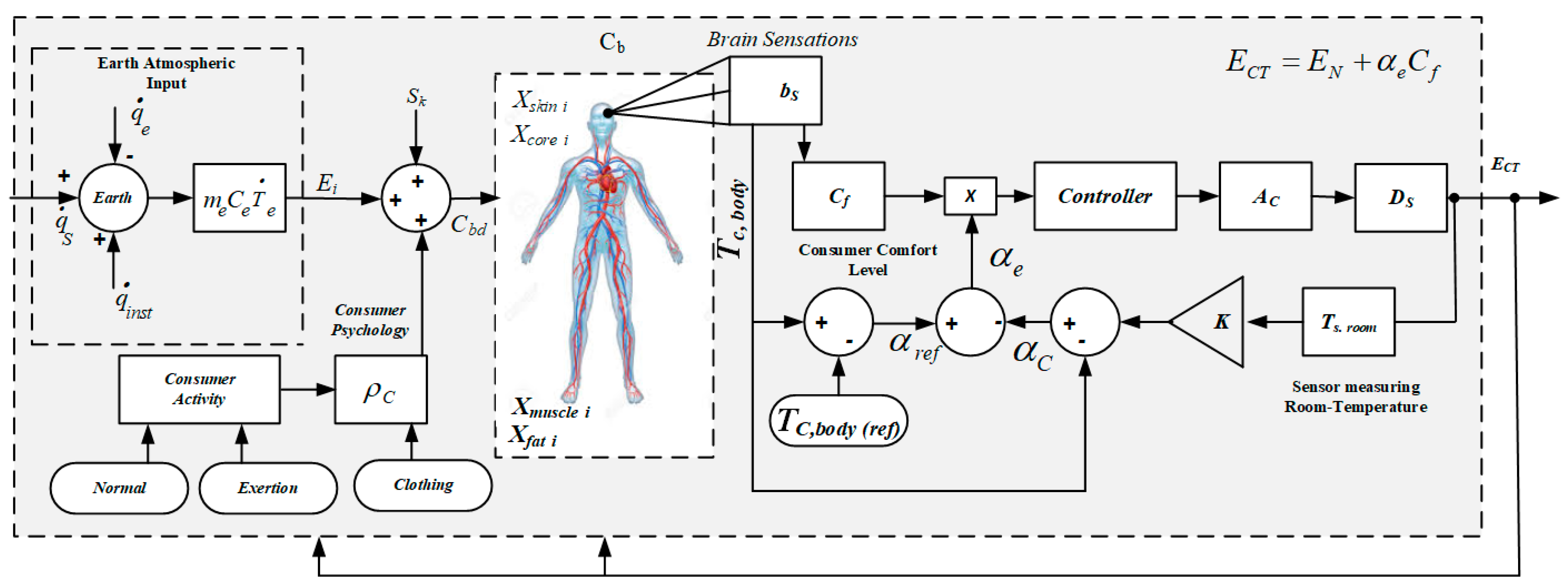
  • To capture the human behavior and responses to the environmental change impact, a CBD response capturing model is developed and analyzed. The model used CBD parameters, such as: (a) Vasodilation, (b) Vasoconstriction, (c) Convection, (d) Conduction, (e) Radiation, (f) Respiration, and (g) Metabolism rate that determine the present state of consumer thermal CL.
  • We develop a comprehensive EMS model incorporating the effects of different EPs, and the real-time data of the surrounding environment. The effects of outdoor environmental fluctuations on indoor parameters are also elaborated mathematically with this proposed model. Building parameters are measured based on sensor data and integrated with EMS.
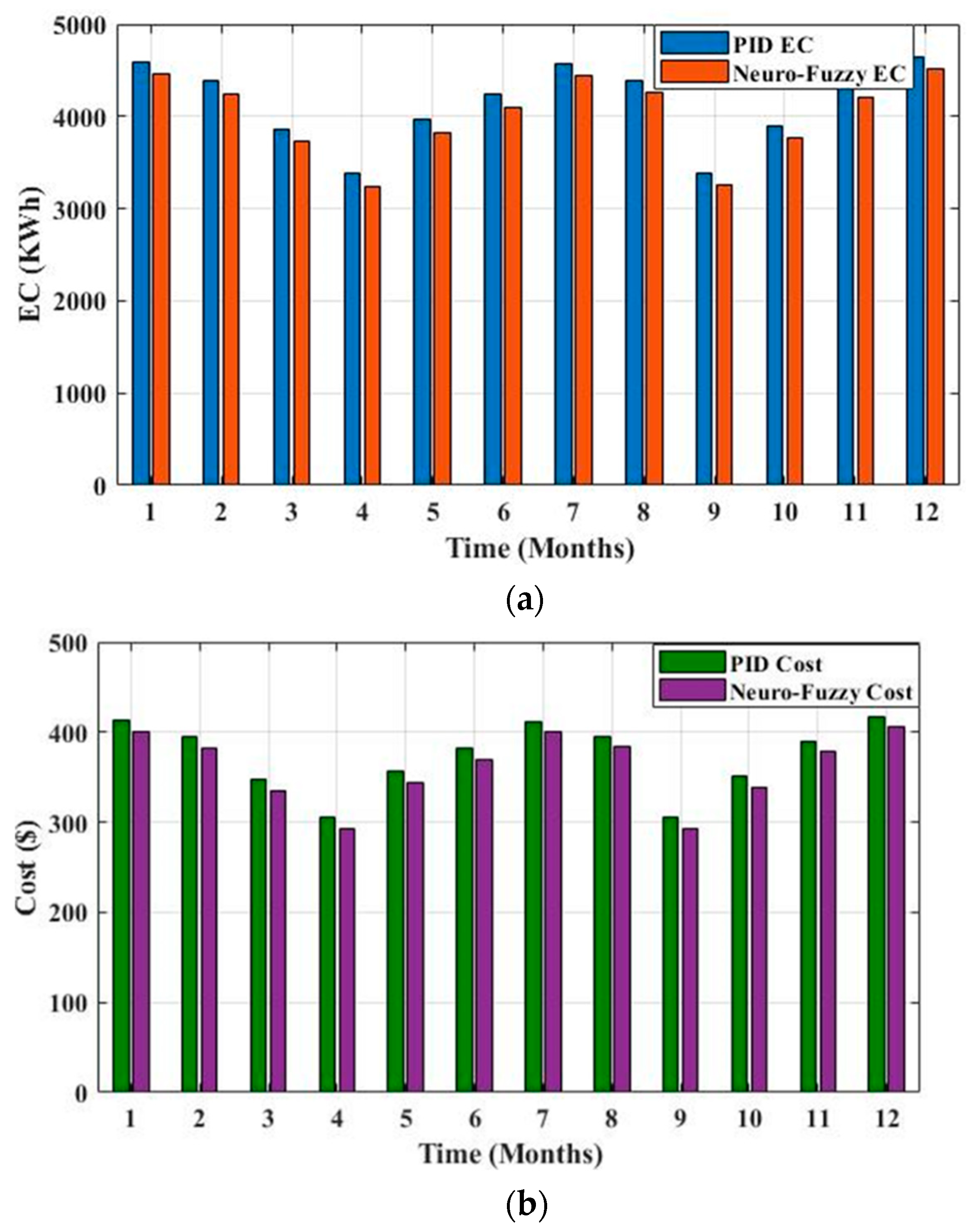
  • To build a stable EMS, we developed a closed-loop control system to control the impact of EPs variations on the CBD. Three different EPs inputs, such as extreme cold, hot persisting, and normal conditions are used to test the designed feedback control system (classical PID and Adaptive Neuro-Fuzzy-Type II). The performance of both controllers is also tested and compared.
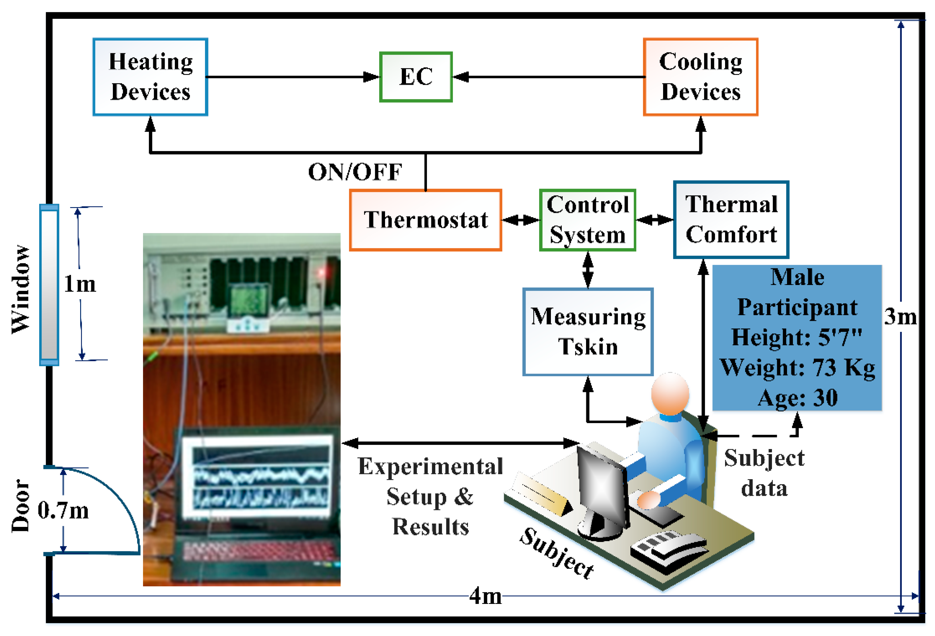
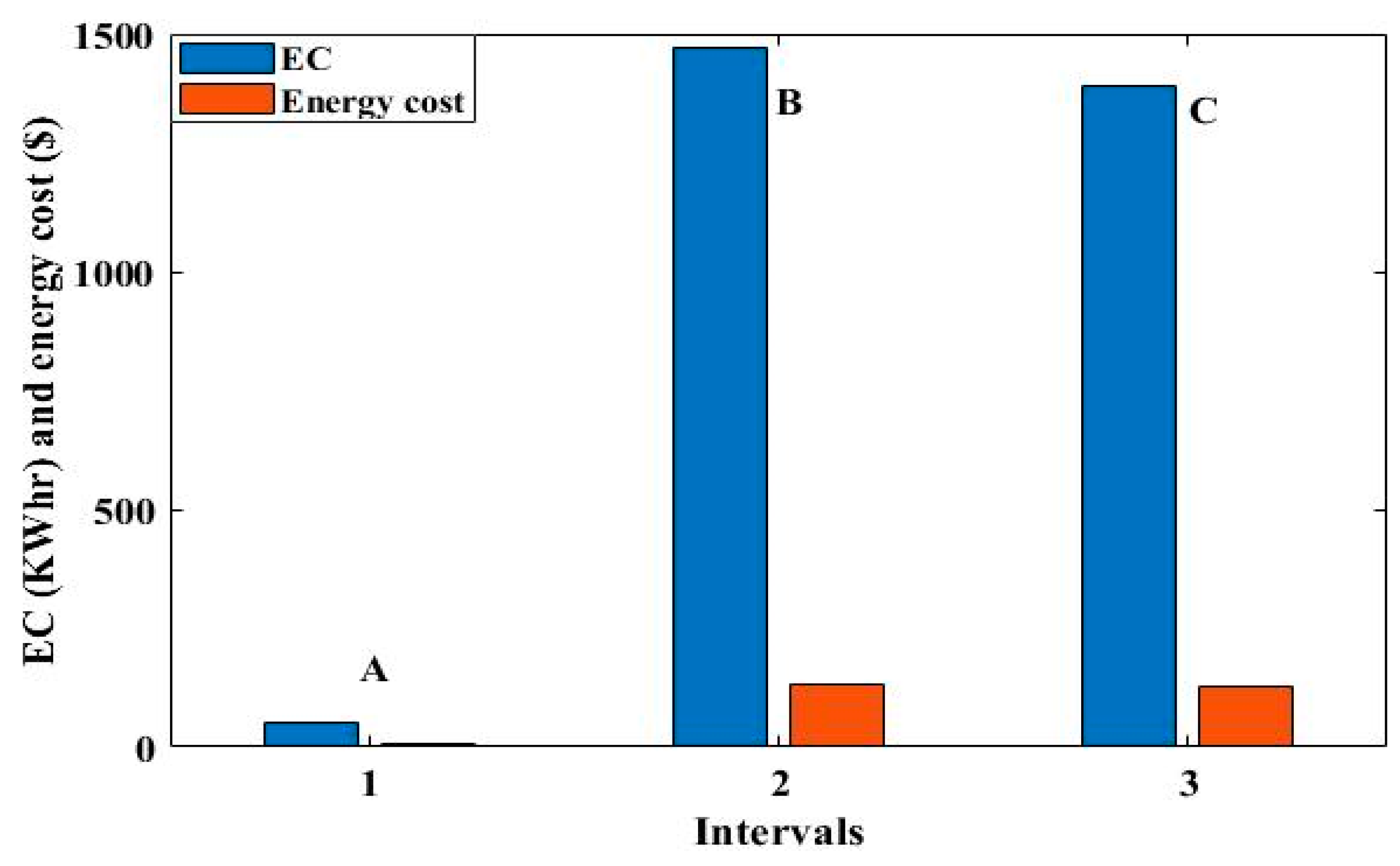
  • Under the EMS model, six different cases for consumer EC are simulated that describe EC reductions and EC cost reductions with PID and NF-II controllers. Moreover, the performance of our proposed model is verified experimentally by developing a smart IoT-based hardware setup using parameters of the winter season as a test case. The IoT board (ESP826) is connected to the Azure IoT Hub platform from Microsoft via the MQTT protocol is used.
The rest of the paper is organized as follows: Section 2 provides a detailed literature review. CBD, basic EPs related to consumer daily life, and their intrinsic effects on the thermal comfort of the consumer body are described in Section 3. Section 4 presents the system model and comfort-based control for desired consumer comfort with optimized EC. Section 5 elaborates the performance evaluation of proposed comfort-based EMS through simulations and hardware experiments. Section 6 concludes the paper with a summary and future work directions.

2. Literature Review

In the literature, numerous works are proposed to handle environmental penetrations on EC and consumer thermal comfort. In [12], the outside air-conditioned area thermal comfort was presented that used on-site observers works, on-spot climatic measurements, and computational fluid dynamics. Further, the authors designed some thermal CL catalogs, such as humidex, cooling power index, wet-bulb globe temperature index, and mean comfort vote. The authors in [13] reviewed thermal comfort in the building sector for heterogeneous and variable indoor climatic conditions. They observed that the residential building sector consumed 40% of total energy and green buildings can play a considerable role to decrease EC. The authors investigated thermal comfort in indoor and outdoor environments [14]. In [15], the authors explored thermal comfort for semi-controlled and fully controlled built environments in workplaces for male, female, and over-weight occupants considering the physical requirements for the workers. The authors in [16] developed an evaporative cooling model and implemented it in different cities in Brazil instead of an air-conditioned environment. The authors suggested that evaporative cooling systems are still more efficient than air conditioners to propitiate thermal comfort and save EC for the regions where wet bulb temperature remains under 24 °C (75.2 °F).
In [17], the authors elaborated on the impact of an open window on EC in unautomated cooling and heating buildings. The authors predicted CL from outdoor temperatures by presenting a mathematical relation while enabling an open window. Another dimension of research is concentrated on perturbations generated by enveloping heat gains of buildings from outside environmental effects. The boost in building heat gain increases EC for cooling systems and perturbs the desired comfort. In [18], the authors implemented an ambient air condition system to save energy and achieve thermal comfort for sleeping persons in bedrooms. The authors also included the effects of conduction through walls, and windows, solar radiation to earth, solar heat flow by windows, and the impact of day and night on the outdoor temperature in their ambient temperature control model. The authors in [19] formulated a cooling and heating system that uses humidifiers or heat exchange systems for thermal comfort and achieved 20–25% reduction in energy cost with 40–50% less CO2 emissions. A hardware control system is built based on OMRON software to observe three basic parameters Air Temperature (AT), Air Velocity (AV), and Relative Humidity (RH) of microclimate to determine thermal comfort for a healthy person [20]. The authors in [21] proposed a TRNSYS software-based model that determines AT and humidity in a building’s room to solve problems linked with thermal comfort in pre-urban and rural areas.
In [22], the authors developed a Personal Comfort System (PCS) including EC devices that cool or heat a person individually rather than in a room or entire building to fulfill thermal comfort requirements for building occupants. In PCS, separate EC devices are used for each segment of the consumer body eliminating discomfort situations from individual body parts and shortened EC. In [23,24], the authors also developed similar models by working on PCS devices. The authors in [25] proposed an HVAC control system for PCS integrating the environment and human data. The proposed system resulted in improved accuracy in predicting thermal preferences considering diverse thermal conditions. In [26], the authors analyzed the outdoor environmental effects on EC of research buildings using real-time data and found no relationship between EC and outdoor environmental variations. Outdoor thermal comfort is achieved using various heat mitigation strategies [27]. The authors in [28] comprehensively reviewed the interaction between indoor environment quality and EC considering passive house buildings. In [29], the authors reviewed the EC and environmental interactions considering a case study from Finland. The effects of climate change on EC and consumer CL are discussed in [30]. Similarly, the effects of global warming on EC in Spain are studied in [31]. The EC of cooling needs to be increased due to global warming.
The summary of the aforementioned works showing the mutual relations between environment parametric variations, EC, and consumer CL is provided in Table 1. The presence of a characteristic for the selected study is denoted by a tick (🗸), while a cross (✕) denotes the absence of the selected characteristic. Moreover, a tabular analysis of related works is provided in Table 2. The related works successfully developed a link between Eps and EC during transient-state and steady-state conditions of outdoor and indoor atmospheres. The impacts of stochastic environmental conditions on consumer CL were explained. However, they do not show the effects of CBDs in defining the energy profiles of consumers.
The underlying shortcomings in the above-related works are: (a) for thermal comfort, no direct relation of the EPs with consumer body was incorporated, only correlations and regressions, predictive mean vote, predicted percentage dissatisfied, computational fluid dynamics, and indices based thermal comfort sensations are modeled, (b) environmental variations and clothing insulations, coefficients of heat transfer, convection, conduction, and radiation were not examined experimentally by dividing consumer body into nodes and segments, (c) no inter-relationship of CBD with EC was developed, only impacts of change in climatic conditions and flexibilities in electricity demands were focused, and (d) no relationship of indoor and outdoor environment was considered for thermal comfort and EC, but effects of CO2 emissions and future weather data were analyzed for heating and cooling systems in residential and commercial buildings. However, none of the prior developed research is commercially available for consumers to be used in buildings.

3. Preliminary Study of the Parameters and Models Used in the System Model

This section provides a detailed study of the environment parameters, a thermal model of a building, consumer body dynamics, and the intrinsic impact of environment parameters that directly affect the comfort level of the human body.

3.1. Environmental Parameters (EPs)

The basic parameter for heat transfer between the consumer body and its nearby environment is determined in terms of AT. All other EPs, such as RH, RT, AV, AP, sweating, shivering, and respiration depend on AT. The RT also influences consumer body temperature like the AT. Bodies exchange heat in the form of RT that depends on the AV. In a dense air environment with less AV, the consumer’s body feels warm which increases blood flow rate and blood vessel size and causes sweating [32]. High AV decreases energy demand on summer days and increases energy demand on winter days because Va2α AT is defined as:
V a = 44.72136 × h k P a d ,
where Va represents the AV (in m/s) and d represents the density of air (in kg/m3). The difference between total pressure and static pressure is represented by hkPa (in kilopascal). The pressure exerted by air is co-dependent on AT and AV. By the Boltzmann equation, the ideal gas law states that the interaction of volume and AP are proportional to AT (VPa α AT). If mass and air density are supposed constant, then AV is directly proportional to AP (Va α Pa). The AP as a function of AV is expressed as:
P a = 21.0881 105.894 × V a 20.9456 V a
The RH directly disturbs thermal comfort of a consumer by affecting their rate of sweating and respiration. High humidity, with a slower evaporation rate, feels warm to consumers. The RH has a direct relationship with dew point temperature (DT) and AT defined as:
R H β ( A T D T ) ,
where β is AT dependent coefficient. The value of the β is taken as 6 at AT of 26.85 °C (80.33 °F) and increases as AT falls until becomes 7.4 at AT of −3.15 °C (26.33 °F).

3.2. Thermal Building Model

The energy consumption within a building in the form of heating and cooling requirements is influenced by its location, climatic conditions, insulating materials, immediate surroundings of the building, and consumer behavior. The most significant climatic factors are outdoor temperature and solar radiation. A generic thermal building model involves several components, such as walls, thermal mass, roof, fenestration, thermal insulation, foundation, and outside sheltering devices. Conduction of walls, ventilation through windows, and the effect of solar radiation through glass windows are the three main factors of heat gain inside the buildings. A room in the house is considered enclosed by ceiling, floor, walls, windows, and doors. Variations in outdoor EPs disturb room indoor temperature by heat gain. A small heat gain ( Q i n t ) is associated with the use of electronic equipment, such as fans, lights, refrigerators, irons, juicers, and microwave ovens inside the buildings. Heat loss through ventilation ( Q v e ) of windows and doors perturbs the room’s internal temperature. The internal temperature of the room also depends on the specific heat capacity of air (c), air density (ρ), and volume of the room (V). The relationship between room AT and heat transferred to or from the room is expressed as [30]:
d T A d t = 1 c ρ V { ( Q s o l + Q i n t ) ( Q t c + Q v e ) }

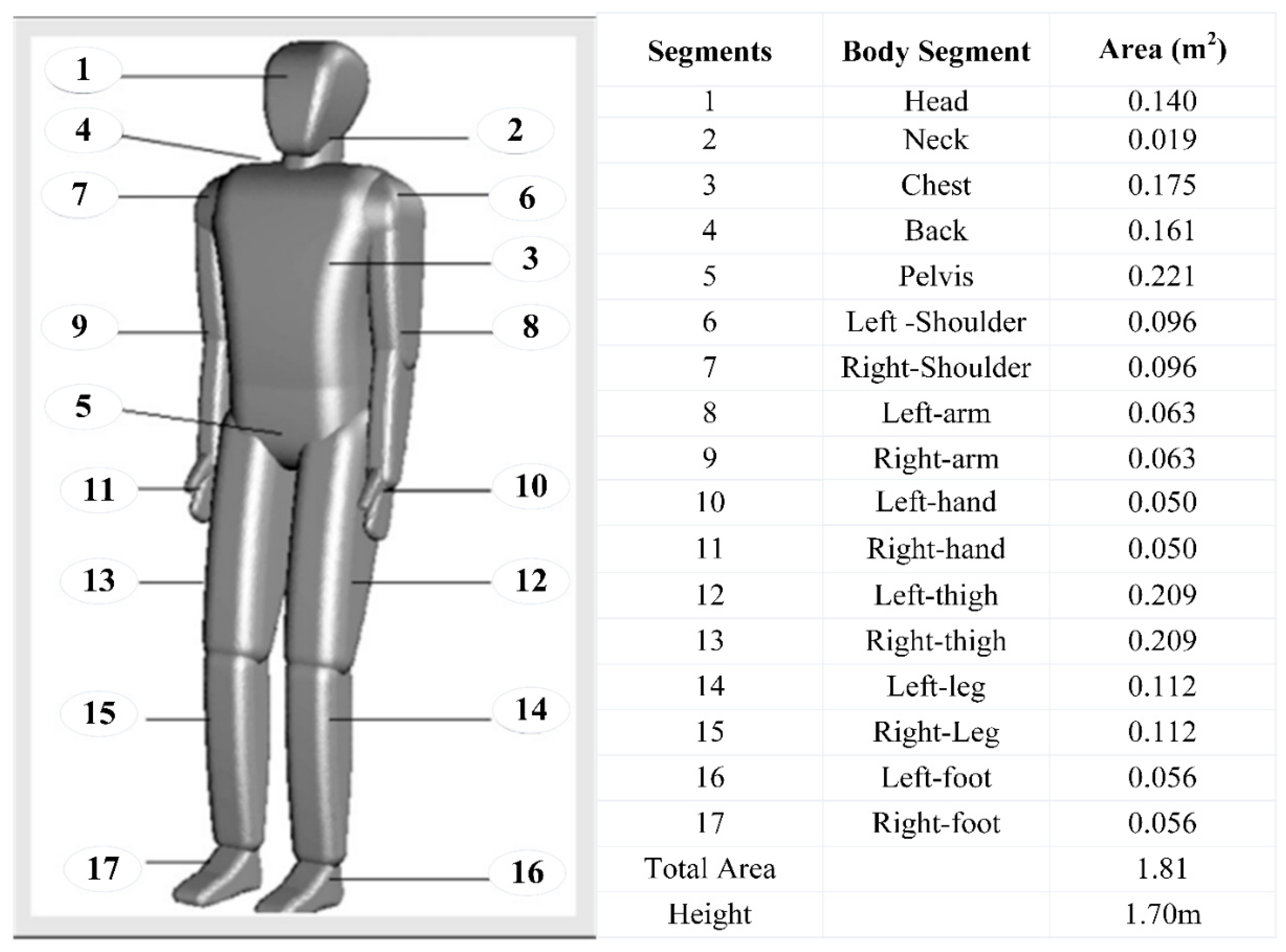
3.3. Consumer Body Dynamics

The 69-Multi-Node (69-MN) thermoregulation system of the Tanabe model is extended for analysis of heat production and heat flows of consumer body [33]. The 69-MN is divided into ‘four’ layers, 17 segments in which the 69th node is the central blood compartment. The segmented distribution concerning the surface area of the corresponding segment of the thermal manikin is shown in Figure 1. Each segment represents four layers and the bloodstream between layers and central blood compartment. Blood supplies temperature (heat) to all layers and nodes. When blood reaches the central blood compartment, it gains the original temperature, which is around 36.7 °C (98.06 °F). Blood circulates throughout all the body segments and exchanges heat through conduction. All the body segments exchange heat with neighboring tissues, nodes, and layers. Heat lost by convection is due to respiration. When the body feels warm, vasodilation takes place with increased blood pressure and the body loses its temperature with sweating.

3.3.1. Heat Balance Equations 69-MN Model

Each segment of consumer body bears a specific heat capacity and temperature. Heat production, heat loss, and heat transfer occur in all segments and layers of the consumer body. Heat is produced through intrinsic and extrinsic biological variation created by basal metabolism Qbasal (a,b), external work W (a,b), and shivering Qhev (a,b). Heat loss of the consumer’s body occurs through respiration and evaporation. When the body loses internal temperature, the bloodstream provides its temperature to segments and layers. Following are heat balancing equations for each segment and layer of the body, where ‘a’ denotes segment number (1–17) and b represents layers of skin, fat, muscle, and core:
C ( a , 1 ) × d T ( a , 1 ) d t = Q ( a , 1 ) B ( a , 1 ) D ( a , 1 ) R E S ( a , 1 )
C ( a , 2 ) d T ( a , 2 ) d t = Q ( a , 2 ) B ( a , 2 ) + D ( a , 1 ) D ( a , 2 )
C ( a , 3 ) d T ( a , 3 ) d t = Q ( a , 3 ) B ( a , 3 ) + D ( a , 2 ) D ( a , 3 )
C ( a , 4 ) d T ( a , 4 ) d t = Q ( a , 4 ) B ( a , 4 ) + D ( a , 3 ) Q t ( a , 4 ) E ( a , 4 )
C ( 69 ) d T ( 67 ) d t = a = 1 17 b = 1 4 B ( a , b )
The above expressions represent the relation of the bloodstream with all layers and segments of the consumer body. All terminologies used in the above equations are illustrated in the upcoming sections.

3.3.2. Heat Capacity of Nodes C (a,b)

The T (a,b) is the temperature of the node, and C (a,b) is its heat capacity. Data of an average man is taken with body weight and surface area of 74.50 kg and 1.87 m2, respectively.

3.3.3. Heat Production Q (a,b)

The Q (a,b) represents heat production of all the segments of the consumer body by basal metabolic Qbasal (a,b) external work W (a,b) and by shivering Chev (a,b). Heat produced by shivering and external work only affects muscle layer, and the values is taken as 0 for other layers. The only positive values are taken for heat produced by mechanical work.
Q ( a , b ) = Q b a s a l ( a , b ) + W ( a , b ) + C h e v ( a , b )
W ( a ,   2 ) = 58.2 ( M e t Q b a s a l ) × A D u · M e t f ( a )
In the above expressions, the metabolic rate (Met) of the entire body, which depends on the activity level of consumer body like running or doing physical exercises will be high. ADu is presenting the surface area of the whole body. The total metabolic rate of all the nodes Qb is taken as 0.778 Met. ADu (a) represents the surface area of a single segment of the consumer’s body.

3.3.4. Rate of Heat Transfer by Blood Stream B (a,b)

The B (a,b) represents a rate of heat exchange by the bloodstream with all nodes and central blood compartment and is expressed below, where ρC specific volume-based blood heat capacity and α is a ratio of heat exchange with the values of 1.07 Wh/(l °C) and 1 Wh/(l °C), respectively. Blood flow rate BF (a,b) exchanges heat of all segments of the consumer body. Blood starts flowing from central blood compartment and circulates in the whole body where it provides or gains heat from all the segments. The effect of work and shivering is considered only for the muscle layer and the values are taken at zero for other layers.
B ( a , b ) = α · ρ C · B F ( a , b ) · ( T ( a , b ) T ( 69 ) )
B F ( a , b ) = B F b a s a l ( a , b ) + ( W ( a , b ) + C h e v ( a , b ) 1.16 )

3.3.5. Heat Transfer by Conduction D (a,b)

The heat transfers from one layer to another neighboring within a single segment by thermal conductance. Heat transfer to a layer in a single segment can occur by conduction D (a,b). All the nodes transfer and receive heat from neighboring layers and body segments by conduction. Conductance among all nodes is represented by Cd (a,b).
D ( a , b ) = C d ( a , b ) × ( T ( a , b ) T ( 69 ) )

3.4. Intrinsic EP Effects on Consumer Body Comfort

The variation in the EPs directly perturbs consumer CL. The internal temperature of the consumer body should be sustained at around 37 °C (98.6 °F), and the heat transfer rate should be at a balanced level. The heat balance state of the consumer body can be determined by combining all the heat transfer equations into a single equation. This will determine the switching action of the EC devices to attain consumer thermal comfort. ASHRAE proposed the formula for heat balance defined as [10]:
M W = C + R + E S K + C R E S + E R E S ,
All above terms in (15) are calculated in W/m2. The M is a rate of energy production through metabolism, C represents convective heat loss, R represents radiative heat loss [33], ESK is evaporative heat loss [33], CRES is respiration heat loss through convection [33], whereas ERES is respiration heat loss through evaporation [33].

4. Modelling, Analysis, and Design of Comfort-Based Smart Energy Management System

This paper presents smart IoT-based energy management and energy consumption optimization model incorporating consumer CL. The block diagram of the system model is illustrated in Figure 2. The block diagram explained the internal and external input parameters affecting the energy consumption of a household and controls the indoor temperature of a building to maintain CL for the occupants. The decision-making of the proposed energy consumption model is based on three input parameters, such as outdoor EPs, indoor environment parameters, and CBD management system. The CBD management system is taken from our previously proposed model [10]. To measure the impact of environmental input variation on the CBD, we proposed a system model presented in [10,11]. We concluded that the EC is the function of EPs, CBD, and psychological effects of consumers as the EPs, consumer psychological effects, and consumer activity level perturb consumer comfort. The cooling and heating appliances of the room are connected to the power supply via IoT board (ESP826) that is connected to the Azure IoT Hub platform from Microsoft via MQTT protocol.
A multiple feedback closed-loop control system is proposed and designed in this paper to ensure consumer comfort with minimized energy cost. The feedback closed-loop control system actuates the cooling and heating appliances via the IoT board based on the inputs from the consumer body and environment to achieve optimum EC of the consumer. The block diagram of the multiple feedback closed-loop control system is shown in Figure 3. It is demanding to maintain consumer CL with optimum consumer EC. An actuating factor αe is introduced, which is the difference between the comfort-based reference factor αref of the consumer body and the actual consumer body threshold factor αc. The αref is the difference between comfort-based reference temperature TC,body (ref) of the consumer body and actual consumer body transient temperature TC,body. Therefore, the first difference is calculated in terms of two preset temperatures, termed as αref. This temperature difference is interfaced with αc. The actual consumer body threshold factor αc is calculated using the gain factor K, the ratio between TC,body, and room temperature Ts,room measured from room sensor. The αe concerning brain sensation-driven consumer comfort level Cf is used as input to the Adaptive Neuro-Fuzzy Type II (NF-II) controller. The NF control algorithm is used for the control and identification of dynamics plants, and PV arrays [34,35]. Moreover, fuzzy logic controller assisted in servo control [36], cycloergometer [37], hydrogen injection into internal combustion engine [38], motion control [39], and induction machines [40]. The NF-II controller is used to actuate the heating and cooling devices via the IoT board based on the error calculated by actual consumer body temperature, surrounding environment temperature, and referenced consumer comfort temperature. The factor αeCf is applied as input to the NF-II controller that controls the actuator triggering by producing a control signal. The optimal consumer comfort and EC are achieved by switched actions of the controller. The ECT = EN + αeCf is the optimum EC to achieve desired consumer CL. As αe approaches zero, ECT approaches EN, and when αe varies, ECT adopts a new value.

4.1. Objective Function

The objective is to achieve thermal comfort for the consumer body and optimize the EC. The skin layer of the consumer body reflects the state of thermal comfort, therefore, thermal comfort is achieved by controlling EPs, such as AT, Va, and Pa. The temperature of each segment of skin is calculated by the following expression:
T ( a , 4 ) = [ ( Q ( a , 4 )   B ( a , 4 ) + D ( a , 4 ) ) { h t a ( T ( a , 4 ) t o ( a ) } A D u ( a ) )   0.06 ( 1 E s w ( a , 4 ) h e ( a ) ( P s k i n , s ( a ) P a ( a ) ) A D u ( a ) ) h e ( a ) ( P s k i n , s ( a )   P a ( a ) A D u ( a ) ) ] / C ( a , 4 )
t o ( a ) = h r   t r + h c   A T h r + h c
The operating temperature can also be calculated for the whole body by the following expression [41]:
t o = A ( V a ) + ( 1 A ) t r
where A is a constant. Its value will be set at 0.5 when the value of AV will be less than ‘2′ m/s. When the value of AV will be in between 0.2 to 0.6 m/s then the chosen value of A will be 0.6. Whenever the value of A V is in between 0.6 to 1 m/s then the value of A will be set 0.7. To achieve desired CL, room temperature is maintained by switching heating or cooling devices to a preferred CL. The equivalent temperature of a room for desired CL can be calculated by the following relationship:
T e q = 0.522 T A + 0.478 t r 0.21 V a   ( 37.8 T A )

4.2. Adaptive Neuro-Fuzzy Type II Controller Used to Control EMS

The NF-II controller is interfaced with the EMS to analyze the reductions in EC and energy cost [42]. The neural networks are used to control information attained from systems although fuzzy logic comprises linguistic information obtained from numerical realities and knowledge. The compensations of both systems are occupied by linking them as an integrated system. The fuzzy logic operates on the concept of membership functions and the degree of membership functions, which is a set normalized range of 0–1. In a fuzzy set, each entity is associated with some degree of membership. The highest value of the degree of membership is one and the lowest is zero. Certain operations that we apply on crisp sets such as union, intersections, and addition can also be performed on a fuzzy set. The closed-loop control structure for the NF-II is shown in Figure 4. The disturbances met by the EPs fluctuations disturb consumer CL. The closed-loop feedback control system incorporates mutual energy exchange by controlling consumer and environment parameters. The difference between consumer comfort temperature and environmental temperature is feedback to the adaptive mechanism and is used to calculate error signals for controlled adaptations of the NF-II. The NF-II control system actuates the actuating system, mutual heat exchange occurs, and achieves consumer comfort level. Moreover, in Figure 4, T r e f is part of the α r e f in Figure 2 and Δ T is part of α e C f in Figure 2.

4.3. Structure of Neuro-Fuzzy Type II Controller

In this article, we combined the neural network with a Type II fuzzy system to analyze the reductions in EC and energy cost. The integration of the neural network with fuzzy systems forms a network with self-learning characteristics, reduces the data complexity, and model uncertainty and imprecision allow reducing the complexity of the data and modeling uncertainty and imprecision. The structure of the Neuro-Fuzzy Type II Controller is visualized in [43]. The type II TSK fuzzy rules used in this paper are considered as:
I f   z 1   i s   A ˜ 1 j   a n d   z 2   i s   A ˜ 2 j   a n d     a n d   z n   i s   A ˜ n j ,   T h e n   y j   i s   i = 1 N w i j z i + b j
where z 1 , z 2 ,   ,   z n are the input variables and y 1 , y 2 ,   ,   y m are the output variables that are considered as linear functions as provided in (20), w i j and b j ( i = 1 ,   ,   n ,   j = 1 ,   ,   m ) are parameters for the consequent part of the rules, and A ˜ i j is the type II fuzzy membership function (Gaussian functions) for the j th rule of the i th input. The model of NF-2 multi-input and single output system [37] is used in this paper. The NF-2 system contains the determination of the appropriate values for the unknown coefficients of the antecedent and the consequent parts of each rule, as Gaussian membership functions are used in this paper for the antecedent part of NF-2. If both c and σ, parameters of the Gaussian function, are taken as uncertain (within certain intervals), the parameter space of the system can become very large. Therefore, only the means c of the membership functions are assumed to be uncertain and the standard deviations are fixed.
In NF-II, for Layer 1 all the external input signals ( z 1 , z 2 ,   ,   z n ) are distributed. In Layer 2, all nodes are associated with individual linguistic terms. Layer 2 is the antecedent part of the rule given in the (20). The linguistic terms are defined using type II fuzzy sets and each membership function of the antecedent part is represented by upper and lower membership functions as μ ¯ ( x ) a n d   μ _ ( x )   o r   A ¯ ( x ) a n d   A _ ( x ) . In the nodes of the second layer, for each external input z i , the membership degree μ ¯   a n d   μ _ to which the input value belongs to a fuzzy set are computed [43]. For the fuzzy inference engine in NF-II, we used ‘min’ and ‘prod’ t-norms implication operators. For Layer 3, the t-norm prod operator is applied to compute the firing powers of each rule using the equation:
f _ = μ _ A ¯ 1 ( z 1 ) μ _ A ¯ 2 ( z 2 )   μ _ A ¯ m ( z m ) ,
f ¯ = μ ¯ A ¯ 1 ( z 1 ) μ ¯ A ¯ 2 ( z 2 )   μ ¯ A ¯ m ( z m ) ,
where * is the t-norm prod operator. Layer 4 represents the consequent part of the rules and calculates the outputs of the linear functions. In Layer 5, the output signals of Layer-3 are multiplied by the output signals of the linear functions. Layer-6 and Layer-7 perform the type of reduction and defuzzification operations, respectively. The inference engine for NF-II is taken from [41]. The output of the NF-II is computed as:
u = p j = 1 M f _ j y j j = 1 M f _ j + q j = 1 M f ¯ j y j j = 1 M f ¯ j
y j = i = 1 N w i j z i + b j
where N is the number of active rules, f _ j and f ¯ j are computed using (21) and (22), y j is the outputs of the linear functions, and u is the output signal of the NF-II. The quantities p and q are the design parameters, which weight the sharing of the lower and upper firing levels of each fired rule determined as given in [43]. Moreover, the parameter update rules for the proposed NF-II system are adapted from [44].

5. Performance Evaluations

5.1. Simulation Settings

Due to the diverse heterogeneity of the EPs, CBD, vigorous interaction and necessities of the occupants, cost functions, precision, time constant, and contradictory challenges in buildings, a controller-based intelligent system is developed. The dynamic model of the consumer body and thermal building model is built in MATLAB/Simulink for the evaluation of differential system equations with PID and NF-II.

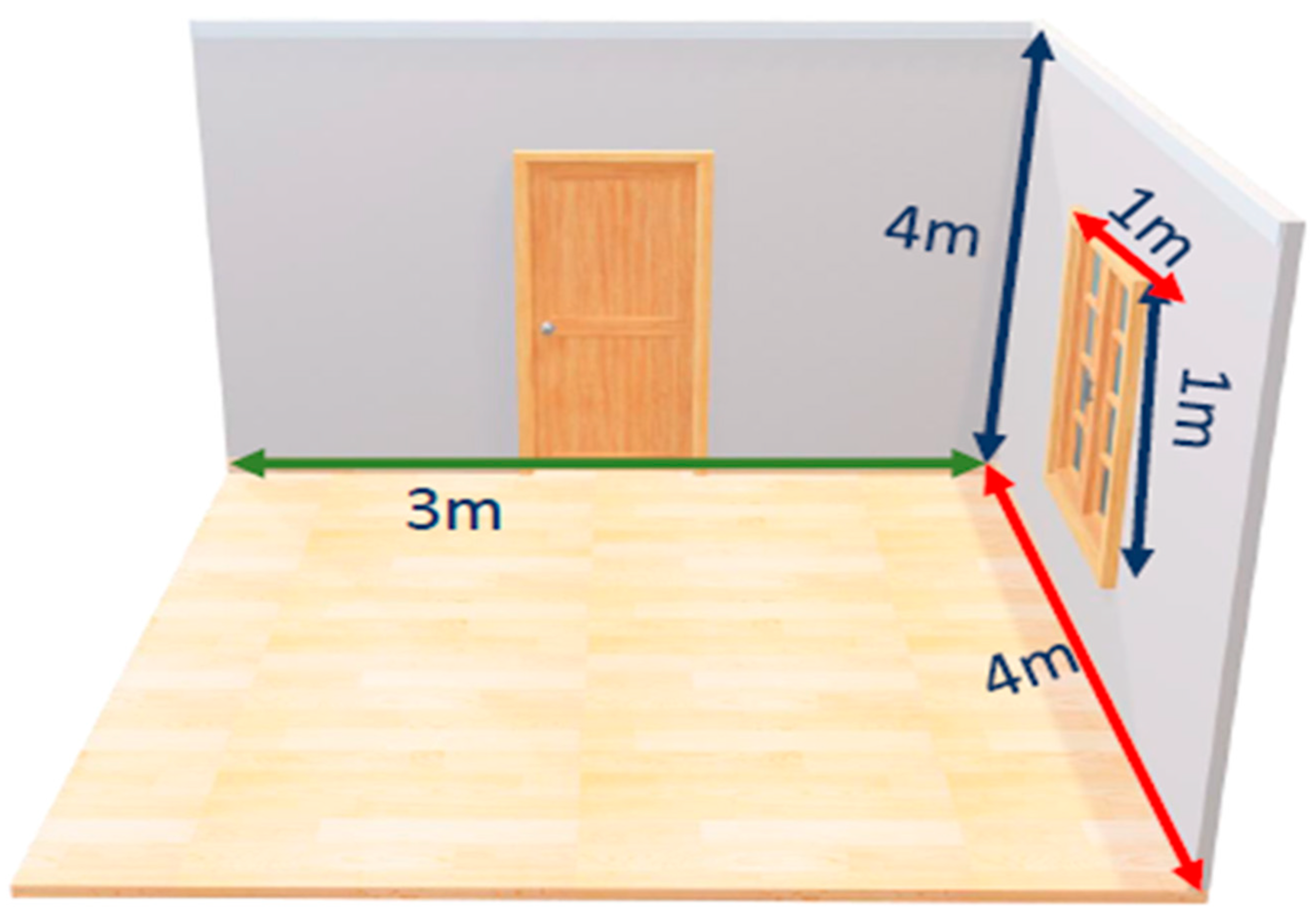
5.2. Parameters of Thermal House

A single-story house with one bedroom is considered, constructed on the ground, and parameters are shown in Figure 5. A house having 30 m in length, 10 m in width, and 4 m in height is considered in the simulation settings. The pitch of the roof is taken as 40 °C (104 °F). The house contains six windows where each window is 1 m in height and 1 m in width. The house contains one bedroom, one kitchen, one living room, and a washroom. The main room of the building is the living room. Thermal heat distribution is assumed as equal for the entire house. The total air capacity of the house is 1005 Jkg−1-K−1, and the density of air is 1.225 Kg/m3. The glass used in windows is 0.01 m thick and glass wool is used as insulating material in walls that increase the total equivalent resistance of walls.

5.2.1. Consumer Data

Consumer response to environmental drifts with cold, hot, and mild conditions perturbs consumer comfort level Cf. The CBD is more sensitive to the outdoor environment, compared to indoor environment parameters. Therefore, the outside spaces widely fluctuate EC for the consumer. Moreover, EC data is shaped considering the consumers’ thermal history. Further, skin temperature Tskin is a more common psychological parameter among various driving forces for perturbing CBD. The radiational temperature of the environment causes pertinent effects on Tskin. Scientists and researchers declared Tskin as an effective controlling parameter for studying CBD. The disturbance in CBD changes with the clothed and unclothed consumers. The EPs and CBD are briefly described in Section 2.

5.2.2. Maximum and Minimum Environmental Data

The environmental fluctuations pose a strong effect on the CBD. The EPs that are considered: AT, RT, AV, PA, and RH are basic variables that directly affect CBD. Among all other EPs, AT has more influence on the CBD. The decrease in the AT causes the air density to increase. Therefore, the pressure of air and the capacity of holding water vapor increase. Due to this effect, the heat loss by respiration and evaporation varies. Human bodies are homeotherms and struggle to keep their internal body temperature around 37 °C (98.6 °F). If any change occurs in internal temperature, the body maintains its internal temperature by sweating or shivering. Therefore, the temperature of the human body will be affected by surrounding variations. All the EPs, such as RH, RT, AP, AV, sweating, shivering, and respiration depend on AT. Analyzed EPs of Abbottabad (Pakistan) for the year 2018 are illustrated in Figure 6 [45].

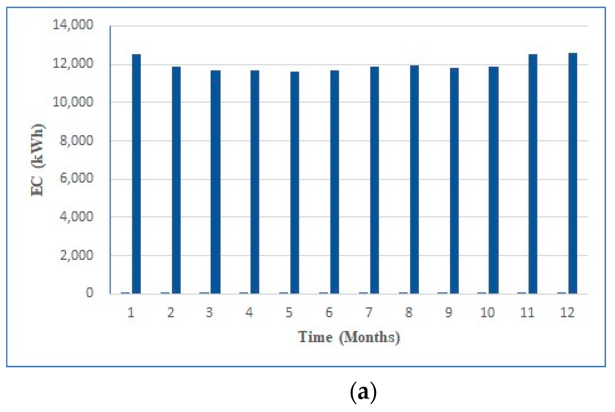
5.3. Energy Consumption (EC) Cases

Six different cases of consumer EC are simulated and analyzed in this section. At experiment time, the temperatures of human body layers extracted from simulation results are shown in Figure 7, Figure 8, Figure 9, Figure 10, Figure 11 and Figure 12.

5.3.1. Case 1: Normal Operation without Consumer Body Comfort

Consumers’ behavior and consumers’ correlation with cooling and heating devices are vital parameters to assess the EC in the buildings. The open loop devices are used to achieve the thermal comfort of the consumer body. The open loop devices are considered in this case. Therefore, this case is categorized as an open loop EC case. Open loop devices work continuously irrespective of consumer CL and consume more energy than switching-based or comfort control-based devices. Therefore, open loop devices are not suitable to achieve desired consumer CL. The results of such types of devices are shown below in Figure 7a,b. Figure 7a depicts the EC (in kWh) of an open loop heating system of a building for one year, while Figure 7b represents the energy cost ($) of an open loop heating system of a building for one year. The $0.09 is considered the unit EC price for the consumer.

5.3.2. Case 2: Set-Point Device Switching

Numerous switching-based heating and cooling devices are commercially available for consumers. Switching-based devices work on the ‘set-point temperature’ that is considered in this case. A switching range is set at which the device ‘Turns ON’ or ‘Turns Off’ from response measuring sensors. As no feedback control with consumer thermal sensation is present, this case is also categorized as an open loop EC case. The set-point devices are unable to achieve desired consumer CL as it is a stochastic function of consumer physiological variations. Generally, the conventional controllers provide poor performance for non-linear processes with large time delays when implemented alone. The aforementioned control systems achieve few energy savings and desired thermal comfort. Devices with set-point switching are also called conventional control-based switching devices. These devices consume less energy as compared to open loop devices. EC of consumers using set-point devices is presented in Figure 8a with the same parameters as used in case 1 of the open loop devices. Whereas the EC of consumers is presented in Figure 8b.

5.3.3. Case 3: Comfort Based Control Incorporating CBD

The objective is to achieve thermal comfort for consumer body and optimize the EC. The skin layer of the consumer’s body reflects a thermal comfort state. To achieve desired CL, room temperature is maintained by switching heating or cooling devices to a preferred CL. The consumer body maintains the blood temperature around 36.7 °C (98.06 °F) in neutral environments. The difference between set point temperature and actual temperature defines the warm and cold environment. If the error signal becomes negative, then the surrounding environment will be cold, whereas a positive error represents a warm environment. The benefits comparison (error calculation) between open loop and closed loop controller (PID, Neuro-Fuzzy Type II) for EC and cost is analyzed in Table 3.
The skin temperature determines the effect of thermal comfort, therefore, the sensor measures and controls only skin temperature. The NF-II-based control system is bidirectionally interfaced to a consumer, the environment, and EC devices. Mutual heat exchange controlled by NF-II achieves thermal comfort for the consumer body by maintaining the indoor temperature and optimizing the EC and energy cost of the consumer. Figure 9a represents the EC of the consumer in kWh, while Figure 9b depicts the consumer energy cost in dollars. The normal activity level of the consumer body is considered as working in an office, typing on the computer, or sitting in a chair, therefore heat produced by mechanical work is considered zero, and the value of metabolism is considered as basal metabolic rate.
The heat transfer to the environment is due to the difference between AT and RT. In this case, RT 35 °C (95 °F) and AT is around 30 °C (86 °F); therefore, the mean skin temperature should be around 34 °C (93.2 °F). RH is kept at about 50% because the value of dry heat transfer is small. As the AT is about 30 °C (86 °F) and RH is 50%, the amount of heat lost by respiration should be around 15 W/m2. Clothing insulation prevents some EPs, so the value of convective heat transfer hc through clothing insulation is considered 3.61. The consumer’s body feels comfortable when there is no gain and loss of heat. In some environmental conditions, the adjustment of clothing is enough to achieve thermal comfort.

5.3.4. Case 4: Extreme Cold Outdoor Environment

The data of an extremely cold environment is simulated to analyze energy savings and cost reductions in electricity bills while achieving thermal comfort by incorporating CBD. PID controller and NF-II controller are used for analysis. RH is considered 60% with RT of 20 °C (68 °F). Heating devices are used to maintain the required comfortable temperature of the room with a feedback control system. NF-II provides 3.04% more savings in EC and EC costs. NF-II controller achieves required thermal comfort more accurately than PID controller. The graphical representation of EC is shown in Figure 10a and the results of cost are shown in Figure 10b.

5.3.5. Case 5: Hot Persisting Conditions

The data of the hot persisting environment is simulated to compare the energy and cost efficiency of the PID controller and NF-II controller; 40%, 47 °C (116.6 °F), 37 °C (98.6 °F), 1 m/s are used as simulation values of RH, AT, RT, and AV, respectively. PID and NF-II-based closed-loop feedback-controlled cooling system is used to achieve the required comfortable temperature of the room. NF-II controller saves 1.98% more EC and EC costs for hot persisting environmental conditions. The results of EC are presented in Figure 11a, while the results of energy cost are shown in Figure 11b.

5.3.6. Case 6: Normal Environmental Conditions

The data of the normal environment is simulated for efficiency analysis between PID controller and NF-II controller. For normal environmental conditions AT varies around 20 °C (68 °F) to 30 °C (86 °F) with RT of 20 °C (68 °F). In this case, closed-loop feedback heating and cooling systems are used for achieving the required thermal comfort temperature. NF-II reduces 3.2% EC and EC costs. The results of EC are shown in Figure 12a and the results of cost are shown in Figure 12b.

5.4. Experimental Work

Case 4.3.3 (Extreme cold outdoor environment EC) is validated experimentally in the Bio-Medical laboratory of COMSATS University Islamabad, Abbottabad Campus, Pakistan. The laboratory is equipped with KL-710, a 16-channel biomedical measuring system with data acquisition cards. The experiment is performed on a 30-year-old subject with a height of 1.7 m and a weight of 73 kg. NF-II controlled the mutual heat exchange between consumer and environment to achieve consumer thermal comfort by actuating switching EC devices via IoT board (ESP826) connected to the Azure IoT Hub platform from Microsoft via MQTT protocol. The schematic diagram of the experiment with subject specifications and room dimensions is shown in Figure 13. A single air conditioning system and two electric heaters with a feedback control system are used as heating and cooling sources that are connected to the IoT board. During experimentation HTC-2A sensor is used for the measurement of RH, indoor AT, and outdoor AT with an accuracy of ±5%.
The experiment was conducted in three Phases A, Phase B, and Phase C. Each phase consists of three hours period in an extremely cold environment. In phase A, the consumer was sitting in resting condition and no heating devices were used. Only the operating temperature, RH around the participant, skin temperature, and heart rate in beats per minute for the participant were measured as shown in Figure 14. In phase A, operating temperature and RH were measured at 62.04 °F and 52%, respectively with slight variations. In the rest condition of the consumer, the skin temperature was measured at 90.7 °F with a heart rate of 79.45 BPM. In this phase, EC was recorded at 50 kWh with an energy cost of $4.5 as no heating devices were used, but only the equipment was consuming energy.
In phase B, a closed-loop feedback control system was used to achieve the required thermal CL for the consumer body. In this phase, the consumer was also at rest condition. At the initial stage of phase B, operating temperature and RH were recorded 63.2 °F and 52%, respectively. The closed-loop system increased the operating temperature by 68.4 °F by switching on the heating system of 2 kW that reducing RH to 46%. When thermal CL was achieved, we recorded a skin temperature of 91.17 °F with a heart rate of 80.9 BPM. The consumer was seated with no experience of direct hot air flow. The system was turned ‘OFF’ and ‘ON’ automatically according to the CBD. The EC and energy cost was recorded as 1470 kWh and $132.3 for this interval.
In phase C, a dumbbell of 10 kg weight was used for exercise by a consumer. Thermal comfort was achieved by resting the body before starting exercise. After 15 min of exercise, the data of the consumer body and EPs were recorded as shown in Figure 14. Skin temperature was measured 91.27 °F with a heart rate of 82 BPM. The RH and room temperature were recorded at 44% and 68.5 °F respectively. EC and energy cost for this phase was measured at 1390 kWh and $125.1, which is less than phase B of the rest condition. The factor behind reduced EC in phase C is internal heat produced by the consumer body through exercise. EC and energy cost for all phases is shown in Figure 15.

5.5. Threats to Validity

The threats to validity may limit our ability to interpret conclusions from the proposed research. Some of the prominent threats to validity related to our study are internal, external, and construct validity. The threats to validity and possible ways to alleviate the threats are discussed as follows.

5.5.1. Internal Validity

The internal validity of the proposed experimental setup can be threatened by three input parameters shown in Figure 2, such as indoor environmental parameters, outdoor environmental parameters, and consumer body dynamics. The accuracy of these intermittent environmental parameters is of great concern and threat to internal validity. The output of the proposed work is acquired in extreme cold conditions and may vary in hot persisting and normal temperature conditions. Moreover, the CBD is provided as input to the experimental setup and can pose a serious threat to internal validity as CBD varies for each subject despite having the same age and height. To avoid poor readings of outdoor environmental parameters, we gathered data from multiple sensors and then leveraged that to avoid validity threats.

5.5.2. External Validity

The prominent threat to external validity is the selection of participants and person experimenting. The experience of a person is a serious threat to external validity and may affect external validity. In our case, the experiment was performed by the staff of the biomedical laboratory. The conclusion can be generalized when the experiment is further conducted by individuals with less, no, and high experience. Furthermore, the geographical conditions are threats to external validity. The general statement can be drawn by experimenting with different geographical conditions and scenarios. Moreover, the sensors (used for acquiring EPs data), subject selection (participant CBD variations), sensors efficiency, and data processing can threaten the external validity of the proposed research. The inefficiency or malfunctioning of sensors can lead to bad data or data loss and may result in controller malfunctioning (closed-loop controller affects the comfort level of the consumer) and higher EC.

5.5.3. Construct Validity

The experiment setup includes various equipment for data acquiring and processing for a closed-loop control system. The possible threat to construct validity is measurement equipment due to inaccurate calibrations. The experimental work was performed by laboratory staff with medium experience in measuring BPM and other dependent variables. To make the experiment constructively valid, the independent variable can be considered to measure the control flow complexity of the proposed experiment composed of various elements.

6. Conclusions and Future Work

In general, the worldwide EC of buildings is about 40% and will move to 60% before long. Buildings (residential and commercial) are those places where single or multiple people work and live. As a trend, consumers wander toward cities for better shelter, consequently, buildings are occupying more and more landscapes of cities. Thus, buildings of cities need great attention to make them energy efficient, intelligent, green, and comfortable. In this regard, to ensure consumer CL, multiple feedback NF-II-based closed-loop control system is proposed and designed, bidirectionally interfaced with the consumer and surrounding environment to achieve consumer comfort with minimized EC. The variations in CBD affected the energy consumption profiles and achieved more savings in EC and EC costs, compared to consumers in rest mode. Moreover, the nonlinear adaptive NF-II-based closed feedback control system efficiently tackles the nonlinearities associated with CBD and stochastic environmental drifts, compared to the PID controller. The experimental validation of the closed feedback control system provided that the proposed setup can be established in universities, residential and commercial buildings, and other indoor places to achieve savings in EC and EC costs. The proposed model will provide various pertinent features, such as (a) energy demand and energy supply optimized management, (b) consumer body and energy appliance interactions, (c) comfort control of consumer body, (d) consumer energy cost reductions, (e) minimized EC, (f) consumer satisfaction and consumer empowerment, and (g) energy forecasting based on environment driven brain-sensations of consumers, geographically located at mountainous, plain, and sea level regions.
In the near future, we will work on the following objectives, such as (a) the implementation of intelligent control systems with dynamic inputs and distributed control is still open, (b) consumer approaches, preferences, and behavior are still a challenging task for real-time implementation and computations, (c) significant future progress of the research must establish quantification of the operative energy savings and assessment of the effect on consumers satisfaction, and (d) certain predictive and adaptive systems must be established for predicting the energy demands and consumers comfort requirements.

Author Contributions

Conceptualization, M.A.N., B.K., M.B.Q. and S.M.A.; Formal analysis, M.A.N., M.B.Q. and S.M.A.; M.A., M.J. and C.A.M.; Methodology, M.A. and S.M.A.; Resources, M.B.Q., Z.U. and M.J.; Software, B.K. and M.J.; Supervision, S.M.A., S.A. and M.B.Q.; Validation, M.A., B.K. and C.A.M.; writing–original draft preparation, M.A.N., S.M.A., M.J. and Z.U.; Writing–review and editing, M.A., M.J., Z.U. All authors have read and agreed to the published version of the manuscript.

Funding

The authors have no external funding.

Acknowledgments

The authors are highly grateful to School of Computing and Communications, Lancaster University, Bailrigg, Lancaster LA1 4YW, for providing full support in conducting the above research work. The authors also thankful to anonymous reviewers and editor, as they helped us a lot to improve the current manuscript.

Conflicts of Interest

The authors declare no conflict of interest.

Abbreviations

AcronymDefinitionAcronymDefinition
ATAir TemperatureEMSEnergy Management System
AVAir VelocityIoTInternet-of-Things
APAir PressureMNMulti-Node
CLComfort LevelNF-IINeuro-Fuzzy-Type II
CBDConsumer Body DynamicsPCSPersonal Comfort System
DTDew Point TemperaturePIDProportional Integral Derivative
ECEnergy ConsumptionRTRadiant Temperature
EPsEnvironmental ParameterRHRelative Humidity
cSpecific heat capacity of airPaAir Pressure
Cfcomfort levelρAir density
VaAir VelocityBF (a,b) Blood flow rate
VVolume of the roomTskinSkin Temperature

References

  1. Shaukat, N.; Ali, S.M.; Mehmood, C.A.; Khan, B.; Jawad, M.; Farid, U.; Ullah, Z.; Anwar, S.M.; Majid, M. A survey on consumers empowerment, communication technologies, and renewable generation penetration within Smart Grid. Renew. Sustain. Energy Rev. 2018, 81, 1453–1475. [Google Scholar] [CrossRef]
  2. Energy Information Administration. 2018. Available online: http://www.eia.doe.gov (accessed on 10 January 2021).
  3. Aslam, S.; Herodotou, H.; Mohsin, S.M.; Javaid, N.; Ashraf, N.; Aslam, S. A survey on deep learning methods for power load and renewable energy forecasting in smart microgrids. Renew. Sustain. Energy Rev. 2021, 144, 110992. [Google Scholar] [CrossRef]
  4. Deka, K.; Bhanja, D.; Nath, S. Fundamental solution of steady and transient bio heat transfer equations especially for skin burn and hyperthermia treatments. Heat Transf. Asian Res. 2019, 48, 361–378. [Google Scholar] [CrossRef]
  5. Li, K.; Su, H.; Chu, J. Forecasting building energy consumption using neural networks and hybrid neuro-fuzzy system: A comparative study. Energy Build. 2011, 43, 2893–2899. [Google Scholar] [CrossRef]
  6. Ashouri, M.; Haghighat, F.; Fung, B.C.; Lazrak, A.; Yoshino, H. Development of building energy saving advisory: A data mining approach. Energy Build. 2018, 172, 139–151. [Google Scholar] [CrossRef]
  7. Koelblen, B.; Psikuta, A.; Bogdan, A.; Annaheim, S.; Rossi, R.M. Thermal sensation models: Validation and sensitivity towards thermo-physiological parameters. Build. Environ. 2018, 130, 200–211. [Google Scholar] [CrossRef]
  8. ASHRAE. Chapter 9 Thermal Comfort, Handbook Fundamentals; American Society of Heating, Refrigeration and Air Conditioning Engineers: Atlanta, GA, USA, 2017; pp. 19–20. Available online: http://courses.washington.edu/me333afe/ASHRAE_Comfort.pdf (accessed on 1 June 2022).
  9. Luo, M.; Cao, B.; Ji, W.; Ouyang, Q.; Lin, B.; Zhu, Y. The underlying linkage between personal control and thermal comfort: Psychological or physical effects? Energy Build. 2016, 111, 56–63. [Google Scholar] [CrossRef]
  10. Ali, S.M.; Khan, B.; Mokryani, G.; Mehmood, C.A.; Jawad, M.; Farid, U. Environment driven consumer EC model incorporating complexities of consumer body dynamics. IET Energy Syst. Integr. 2019, 1, 53–64. [Google Scholar] [CrossRef]
  11. Wang, Z.; Nazaripouya, H.; Ali, S.M.; Mokryani, G.; Khan, B.; Mehmood, C.A.; Jawad, M.; Alizadeh-Mousavi, O.; Jaton, J. Smart Energy System for Human Body Control, IEEE eNewsletter Smart Grid Applications and Enhancements 2019. Available online: https://smartgrid.ieee.org/bulletins/february-2019/smart-energy-system-for-human-body-control (accessed on 20 August 2020).
  12. Ghani, S.; Bialy, E.M.; Bakochristou, F.; Gamaledin, S.M.A.; Rashwan, M.M.; Hughes, B. Thermal comfort investigation of an outdoor air-conditioned area in a hot and arid environment. Sci. Technol. Built Environ. 2017, 23, 1113–1131. [Google Scholar] [CrossRef] [Green Version]
  13. Mishra, A.K.; Loomans, M.G.L.C.; Hensen, J.L. Thermal comfort of heterogeneous and dynamic indoor conditions—An overview. Build. Environ. 2016, 109, 82–100. [Google Scholar] [CrossRef] [Green Version]
  14. Poel, B.; van Cruchten, G.; Balaras, C.A. Energy performance assessment of existing dwellings. Energy Build. 2007, 39, 393–403. [Google Scholar] [CrossRef]
  15. Rupp, R.F.; Kim, J.; de Dear, R.; Ghisi, E. Associations of occupant demographics, thermal history and obesity variables with their thermal comfort in air-conditioned and mixed-mode ventilation office buildings. Build. Environ. 2018, 135, 1–9. [Google Scholar] [CrossRef]
  16. Santamouris, M.; Cartalis, C.; Synnefa, A.; Kolokotsa, D. On the impact of urban heat island and global warming on the power demand and electricity consumption of buildings—A review. Energy Build. 2015, 98, 119–124. [Google Scholar] [CrossRef]
  17. Wang, H.; Chen, Q. Impact of climate change heating and cooling energy use in buildings in the United States. Energy Build. 2014, 82, 428–436. [Google Scholar] [CrossRef] [Green Version]
  18. Mao, N.; Pan, D.; Li, Z.; Xu, Y.; Song, M.; Deng, S. A numerical study on influences of building envelope heat gain on operating performances of a bed-based task/ambient air conditioning (TAC) system in energy saving and thermal comfort. Appl. Energy 2017, 192, 213–221. [Google Scholar] [CrossRef]
  19. Berger, T.; Amann, C.; Formayer, H.; Korjenic, A.; Pospischal, B.; Neururer, C.; Smutny, R. Impacts of climate change upon cooling and heating energy demand of office buildings in Vienna, Austria. Energy Build. 2014, 80, 517–530. [Google Scholar] [CrossRef]
  20. Tanabe, S.I.; Kobayashi, K.; Nakano, J.; Ozeki, Y.; Konishi, M. Evaluation of thermal comfort using combined multi-node thermoregulation (65MN) and radiation models and computational fluid dynamics (CFD). Energy Build. 2002, 34, 637–646. [Google Scholar] [CrossRef] [Green Version]
  21. Ouédraogo, E.; Coulibaly, O.; Imbga, K.B.; Koala, O.A.G.; Ouédraogo, A.; Kieno, F.P.; Bathiebo, D.J. Designing an Energy-Efficient Building in a Context of Helping Self-Build. Am. J. Energy Eng. 2018, 6, 29. [Google Scholar] [CrossRef]
  22. Luo, M.; Arens, E.; Zhang, H.; Ghahramani, A.; Wang, Z. Thermal comfort evaluated for combinations of energy-efficient personal heating and cooling devices. Build. Environ. 2018, 143, 206–216. [Google Scholar] [CrossRef] [Green Version]
  23. Shahzad, S.; Calautit, K.; Wei, S.; Tien, P.W.; Calautit, J.; Hughes, B. Analysis of the thermal comfort and energy performance of a thermal chair for Open Plan Office. J. Sustain. Dev. Energy Water Environ. Syst. 2020, 8, 373–395. [Google Scholar] [CrossRef]
  24. Song, W.; Zhang, Z.; Chen, Z.; Wang, F.; Yang, B. Thermal comfort and energy performance of Personal Comfort Systems (PCS): A systematic review and meta-analysis. Energy Build. 2022, 256, 111747. [Google Scholar] [CrossRef]
  25. Li, D.; Menassa, C.C.; Kamat, V.R. Personalized human comfort in indoor building environments under diverse conditioning modes. Build. Environ. 2017, 126, 304–317. [Google Scholar] [CrossRef]
  26. Cruz Rios, F.; Naganathan, H.; Chong, W.K.; Lee, S.; Alves, A. Analyzing the impact of outside temperature on energy consumption and production patterns in high-performance research buildings in Arizona. J. Archit. Eng. 2017, 23, C4017002-1. [Google Scholar] [CrossRef]
  27. Taleghani, M. Outdoor thermal comfort by different heat mitigation strategies—A Review. Renew. Sustain. Energy Rev. 2018, 81, 2011–2018. [Google Scholar] [CrossRef]
  28. Wang, Y.; Kuckelkorn, J.; Zhao, F.-Y.; Spliethoff, H.; Lang, W. A state of art of review on interactions between energy performance and indoor environment quality in Passive House Buildings. Renew. Sustain. Energy Rev. 2017, 72, 1303–1319. [Google Scholar] [CrossRef]
  29. Holma, A.; Leskinen, P.; Myllyviita, T.; Manninen, K.; Sokka, L.; Sinkko, T.; Pasanen, K. Environmental impacts and risks of the National Renewable Energy Targets—A review and a qualitative case study from Finland. Renew. Sustain. Energy Rev. 2018, 82, 1433–1441. [Google Scholar] [CrossRef]
  30. Kalvelage, K.; Passe, U.; Rabideau, S.; Takle, E.S. Changing climate: The effects on energy demand and human comfort. Energy Build. 2014, 76, 373–380. [Google Scholar] [CrossRef]
  31. Pablo-Romero, M.D.P.; Sánchez-Braza, A.; González-Jara, D. Economic growth and global warming effects on electricity consumption in Spain: A sectoral study. Environ. Sci. Pollut. Res. 2022, 1–17. [Google Scholar] [CrossRef]
  32. Geography and Wind—Lowa Energy Center. 2018. Available online: http://www.iowaenergycenter.org/wind-energy-manual/wind-and-wind-power/geography-and-wind (accessed on 15 October 2018).
  33. Kobayashi, Y.; Tanabe, S.I. Development of JOS-2 human thermoregulation model with detailed vascular system. Build. Environ. 2013, 66, 1–10. [Google Scholar] [CrossRef]
  34. Solis-Cisneros, H.I.; Sevilla-Camacho, P.Y.; Robles-Ocampo, J.B.; Zuñiga-Reyes, M.A.; Rodríguez-Resendíz, J.; Muñiz-Soria, J.; Hernández-Gutiérrez, C.A. A dynamic reconfiguration method based on neuro-fuzzy control algorithm for partially shaded PV arrays. Sustain. Energy Technol. Assess. 2022, 52, 102147. [Google Scholar] [CrossRef]
  35. Farid, U.; Khan, B.; Ullah, Z.; Ali, S.M.; Mehmood, C.A.; Farid, S.; Sajjad, R.; Sami, I.; Shah, A. Control and identification of dynamic plants using adaptive neuro-fuzzy type-2 strategy. In Proceedings of the 2017 International Conference on Energy Conservation and Efficiency (ICECE), Lahore, Pakistan, 22–23 November 2017. [Google Scholar]
  36. Torres-Salinas, H.; Rodríguez-Reséndiz, J.; Cruz-Miguel, E.E.; Ángeles-Hurtado, L.A. Fuzzy logic and genetic-based algorithm for a servo control system. Micromachines 2022, 13, 586. [Google Scholar] [CrossRef] [PubMed]
  37. Ensastiga, S.A.; Rodríguez-Reséndiz, J.; Estévez-Bén, A.A. Speed controller-based fuzzy logic for a biosignal-feedbacked cycloergometer. Comput. Methods Biomech. Biomed. Eng. 2021, 25, 750–763. [Google Scholar] [CrossRef] [PubMed]
  38. Macias-Bobadilla, G.; Becerra-Ruiz, J.D.; Estévez-Bén, A.A.; Rodríguez-Reséndiz, J. Fuzzy Control-based system feed-back by OBD-II data acquisition for complementary injection of hydrogen into internal combustion engines. Int. J. Hydrogen Energy 2020, 45, 26604–26612. [Google Scholar] [CrossRef]
  39. García-Martínez, J.R.; Cruz-Miguel, E.E.; Carrillo-Serrano, R.V.; Mendoza-Mondragón, F.; Toledano-Ayala, M.; Rodríguez-Reséndiz, J. A PID-type Fuzzy Logic Controller-based approach for motion control applications. Sensors 2020, 20, 5323. [Google Scholar] [CrossRef] [PubMed]
  40. Zeb, K.; Uddin, W.; Islam, S.U.; Khan, I.; Ishfaq, M.; Ullah, Z.; Haider, A.; Kim, H.J. Adaptive Fuzzy Logic Controller for indirect field oriented controlled induction motor. In Proceedings of the 2019 2nd International Conference on Computing, Mathematics and Engineering Technologies (iCoMET), Sukkur, Pakistan, 30–31 January 2019. [Google Scholar]
  41. Griefahn, B.; Künemund, C.; Gehring, U. The significance of air velocity and turbulence intensity for responses to horizontal drafts in a constant air temperature of 23 C. Int. J. Ind. Ergon. 2000, 26, 639–649. [Google Scholar] [CrossRef]
  42. Soyguder, S. Intelligent system based on wavelet decomposition and neural network for predicting of fan speed for energy saving in HVAC system. Energy Build. 2011, 43, 814–822. [Google Scholar] [CrossRef]
  43. Mendel, J.M. Uncertain Rule-Based Fuzzy Logic System: Introduction and New Directions; Prentice Hall: Upper Saddle River, NJ, USA, 2001. [Google Scholar]
  44. Biglarbegian, M.; Melek, W.W.; Mendel, J.M. On the stability of interval type-2 TSK fuzzy logic control systems. IEEE Trans. Syst. Man Cybern. Part B (Cybern.) 2010, 40, 798–818. [Google Scholar] [CrossRef]
  45. Historical Average Weather. Available online: https://www.worldweatheronline.com (accessed on 20 October 2019).
Figure 1. Thermal Manikin.
Electronics 11 02622 g001
Figure 2. Proposed smart energy management system incorporating consumer CL.
Electronics 11 02622 g002
Figure 3. Closed Loop Feedback Controller-based switching and actuating system.
Electronics 11 02622 g003
Figure 4. The closed-loop control structure for adaptive Neuro-Fuzzy Type-II.
Electronics 11 02622 g004
Figure 5. 3D View of thermal room.
Electronics 11 02622 g005
Figure 6. Environmental data analysis.
Electronics 11 02622 g006
Figure 7. (a) EC and (b) energy cost of open loop system.
Electronics 11 02622 g007aElectronics 11 02622 g007b
Figure 8. (a) EC and (b) energy cost of set point switching devices.
Electronics 11 02622 g008aElectronics 11 02622 g008b
Figure 9. (a) EC and (b) energy cost of NF-II control system.
Electronics 11 02622 g009
Figure 10. (a) EC and (b) energy cost of PID and adaptive NF-II control system.
Electronics 11 02622 g010
Figure 11. (a) EC and (b) energy cost of PID and adaptive NF-II control system.
Electronics 11 02622 g011
Figure 12. (a) EC and (b) energy cost of PID and adaptive NF-II control system.
Electronics 11 02622 g012
Figure 13. The schematic diagram of the experimental setup with subject specifications and room dimensions.
Electronics 11 02622 g013
Figure 14. Skin temperature, room temperature, relative humidity, and BPM of phases A, B, and C.
Electronics 11 02622 g014
Figure 15. Energy consumption and energy cost of phases A, B, and C.
Electronics 11 02622 g015
Table 1. State-of-the-art works on mutual interactions of energy consumption, comfort level, and environmental parametric variations.
Ref.ECEMMEVEDHBIEHMMCOPCIECCIPCCHCHEEC
[12]🗸🗸🗸🗸
[13]🗸🗸🗸🗸🗸🗸🗸🗸
[14]🗸🗸🗸🗸🗸
[15]🗸🗸🗸🗸🗸🗸🗸
[16]🗸🗸
[17]🗸🗸
[18]🗸🗸
[19]🗸🗸🗸🗸🗸
[20]🗸🗸🗸🗸🗸🗸🗸
[21]🗸🗸🗸🗸🗸🗸
[22]🗸🗸🗸🗸🗸🗸🗸
[23]🗸🗸🗸
[24]🗸🗸🗸🗸🗸🗸
[25]🗸🗸🗸🗸🗸
[26]🗸🗸🗸🗸🗸
[27]🗸🗸
[28]🗸🗸
[29]🗸🗸🗸
[30]🗸🗸🗸🗸
This work🗸🗸🗸🗸🗸🗸🗸🗸🗸🗸🗸
Abbreviations: EC: energy consumption; EMM: environmental mathematical model; EV: environmental variation; ED: energy demand; HBIE: human body interaction with environments; HMM: human body mathematical model; COP: climatic outdoor parameters; CIEC: climatic impacts on EC; CIP: climatic indoor parameters; CCHC: climatic change and human comfort; HEEC: humidity effect on EC.
Table 2. Related works.
Ref.Research FocusData AnalysisFindings
[26]Effects of outdoor climatic parameters on buildings’ energy consumption and production
  • real-time data of four research buildings and presented correlation and regression between EC, temperature, and solar energy generation
  • outside AT has no influence on EC and solar energy generation
  • no correlation was found between EC and environmental parameters
[27]Human CL and COP
  • comparative analysis of EC based on 320 climatic conditions
  • human thermal CL examined in open areas
  • thermal CL was improved at pedestrian level considering foliage as superiority
  • thermal CL was improved in urban areas
  • heat reduction strategies were analyzed
[31]Temperature effects on power demand of a firm
  • real-time data was extracted from firms for the year 2009–2013
  • temperature sensitivity varies across various sectors
  • Aggregated energy demand in Spain was temperature insensitive
  • the highest sensitiveness was recorded by service sector firms
Table 3. Benefits Comparison (calculating error) between open loop and closed loop controller (PID, Neuro-Fuzzy Type II) Energy consumptions and Cost.
Energy Consumptions (kWh)
ControllerHours
123456789101112
PID532059806100625062506500600060006150584052705320
Neuro-Fuzzy Type II555061806500655065506800640063006650630055005550
Cost ($)
ControllerHours
123456789101112
PID520550570585610610570570585550480520
Neuro-Fuzzy Type II570600610615640640610610565600530570
Publisher’s Note: MDPI stays neutral with regard to jurisdictional claims in published maps and institutional affiliations.

