Abstract
In this paper, a study on vehicle lateral motion control using an in-wheel motor (IWM) based on tire cornering stiffness estimation is presented. The main purpose of this paper is to develop a lateral motion control that can be implemented considering practical issues in real-world vehicle applications such as driver comfort, high availability, and stable control accuracy. The proposed lateral motion controller for yaw rate tracking is intended to improve vehicle cornering agility. In this paper, we develop a model-based controller with a feedforward control term to accomplish this. In particular, a change in tire cornering stiffness according to the size of the tire slip angle is reflected to improve control accuracy. Finally, the Weighted Least Square (WLS) allocation method optimally distributes the IWM torque to each wheel. Simulation studies confirm that some evaluation factors are improved in terms of cornering performance compared to conventional control algorithms.
1. Introduction
With advances in automotive technology and increasing demand for driving pleasure, many car manufacturers are striving to develop a variety of high-performance vehicles—in particular, a high-performance vehicle capable of providing stable and agile cornering meets drivers’ demands for fun driving. A high-end automaker drew attention by applying a side slip control system for powerful and sophisticated vehicle cornering [1]. In addition, the e-vectoorc project [2], jointly conducted by several European universities, auto parts manufacturers, and auto manufacturers, received a lot of attention after years of R&D to improve the cornering performance of electric vehicles—it is currently attracting the attention of many automotive researchers.
In this paper, we developed a vehicle lateral motion control using an in-wheel motor (IWM) as an actuator, which is suitable for the development of precise model-based control of vehicle lateral motion. The electric vehicle in this paper is equipped with an IWM on the front wheel. Among electronic drivetrains, IWM has received great interest from many automakers over the past few decades due to the following advantages [3]: (1) It can generate both forward and reverse torque, allowing driving and braking. (2) IWM can generate the exact wheel torque the driver needs. This accurate wheel torque generation is an important factor in determining the accuracy of vehicle motion control. (3) Since there is no transmission device between the IWM and the wheel, the transmission efficiency of the IWM torque is very high [3,4]. Many experts expect IWMs to overcome the limitations of mechanical differential devices such as slow response times and low environmental friendliness [5,6]. Vehicle side motion control requires these advantages of IWM to realize precise motion control [7]. The difference in left and right torque can help the vehicle follow the driver’s intended line without longitudinal deceleration. It is considered an advantageous chassis control system due to the growing demand for high-performance vehicles [8].
1.1. Literature Review
Reference [7] proposed an algorithm based on a proportional-integral-derivative (PID) feedback controller with various gains, but the limits of the control input and IWM torque were not considered during the controller design process. Some powerful control techniques have been proposed: Reference [8] proposed the integration of a yaw rate and side slip controller (a powerful H-infinity controller) based on the proposed phase plane analysis to allow for consistently high lateral slip angle values. However, feedback errors in the estimated side-slip angle can cause stability issues. Reference [9] developed an integrated sliding mode controller (SMC) that must be robust to tire model uncertainty, but chattering issues in signed feedback terms in this integrated SMC may be of concern. Studies using the optimal control technique are as follows: Reference [10] presented an optimal control technique based on linear matrix inequality. Addtionally, Kasinathan et al. [11] proposed a limited optimization algorithm of tire force, but computational burden problems may arise in these algorithms. Reference [12] presented a model predictive control algorithm involving human behavior models but required large amounts of road preview data.
1.2. Contributions
In terms of vehicle-side motion control using IWM, existing studies have overlooked practical issues such as: (1) Large oscillating IWM torque in high-gain feedback term deteriorates riding comfort. (2) IWM’s actual usable torque range is strictly limited by IWM’s T-N (Torque-Rotational Speed) curve and IWM battery overcharge protection. (3) Changes in tire cornering stiffness should be reflected in the controller design.
Therefore, the purpose of this paper was to develop a new vehicle lateral motion controller considering the practical problems of IWM. This was primarily aimed at improving cornering performance on roads with a high tire-to-road friction coefficient. Therefore, the driver’s driving pleasure could be obtained in quantitative terms while improving the vehicle’s cornering agility [13,14]. To this end, a model-based controller was determined as a controller type for developing a practical control system that takes into account various problems encountered in real-world automotive applications; it attempted to follow the yaw rate criterion, which is a function of driver commands (steer angle and longitudinal speed).
In this paper, we propose the development of a practical yaw rate tracking controller using IWM in consideration of the limitations of existing studies. The main contributions are summarized as follows: (1) The tire cornering stiffness estimate from the previously developed vehicle condition estimation logic is reflected in the controller design. As a result, the feedforward term of the model-based controller can improve the vehicle cornering performance. (2) The WLS (Weighted Least Square) allocation method optimally distributes IWM torque with consideration to the characteristics of IWM. (3) With its simple structure, the entire algorithm can be easily implemented with a low computational burden.
1.3. Contents of Paper
This paper consists of six sections: Section 2 discusses vehicle modeling. Next, Section 3 deals with the design of the vehicle lateral motion controller to comply with the yaw rate criterion. Section 4 also presents a newly designed torque distribution algorithm. Then, Section 5 evaluates the effectiveness of the proposed algorithm through several evaluation factors in the simulation study, and Section 6 concludes the paper.
2. Vehicle Modeling
The vehicle bicycle model assumes that left and right wheels are lumped together into a single wheel [15]. In this paper, Figure 1 represents a vehicle bicycle model. Since it is assumed that the wheel is located on the center line, the concentrated tire lateral forces and are expressed in the front and rear tire coordinate systems, respectively. Additionally, this vehicle bicycle model assumes that the vehicle motion is restricted to the plane and that there is no vertical movement. In the car body coordinate system, the moment and lateral force balance equations are derived as:
where is the vehicle yaw moment of inertia, additional yaw moment, and m the total mass of the vehicle. Additionally, and are the center of gravity (CG)-front and CG-rear axle distances, respectively: . In (1), the concentrated tire lateral forces on the front and rear axles and can be derived as follows:

Figure 1.
Diagram of the vehicle bicycle model.
For a small side slip angle , the front and rear tire slip angles and in the tire coordinate system are defined as follows:
Assuming that the lateral tire force is linearly proportional to the tire slip angle ( and ), the dynamic equation for the vehicle bicycle model is derived as follows:
Since the cornering stiffness of the tire is assumed to be linearly proportional to the tire normal force, and can be normalized by the front normal force and the rear normal force, respectively [16]. Therefore, it is as written in the following detailed representation:
At this point, the lumped vertical tire forces of the front and rear axles can be obtained by the open-loop calculation:
where is the height of CG, and the normalized cornering stiffness () is divided by the nominal parameter and the unknown . The nominal parameter is the slope in the linear domain of the normalized tire lateral force, as shown in Figure 2. However, it cannot be denied that fixed without adjustment in the non-linear region reduces the accuracy of the tire lateral force. [16]. When the non-linear region is reached, the slope decreases. The unknown variable can be expressed as a change in slope. In order to be robust to such road uncertainty, unknown variables and , i.e., changes in cornering stiffness, must be estimated.
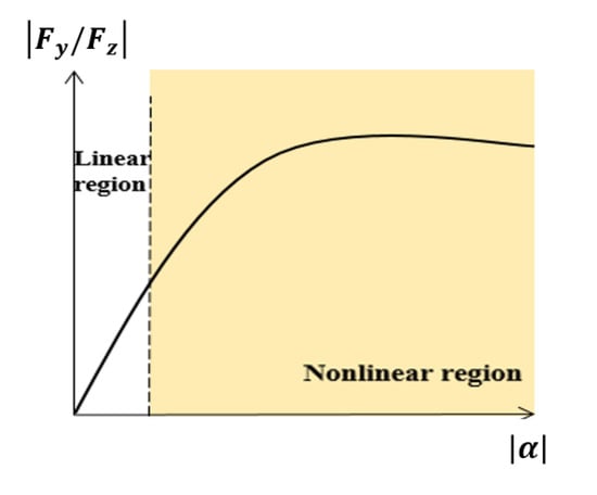
Figure 2.
Normalized lateral tire force versus tire slip angle.
3. Controller Design
Figure 3 shows the block diagram of the overall control algorithm. The vehicle state estimator already developed by our research group [4] outputs the estimated side slip angle and the tire cornering stiffness values , . Here, vehicle parameters , , and were used as constant values. Research on improving control accuracy by combination with real-time estimation algorithms of , , and will be performed in the future.
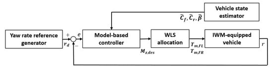
Figure 3.
Block diagram of the overall control algorithm.
3.1. Yaw Rate Reference Generator
In general, the steady state of the bicycle model (when , , and in (4)) is utilized to derive the yaw rate criterion for vehicle cornering [17]. At this time, when aiming for neutral steering, which is an ideal cornering situation, the yaw rate standard was designed as follows [18,19]:
This includes the driver’s steering command and the vehicle longitudinal velocity .
3.2. Model-Based Controller
To track the yaw rate reference, the model-based controller was designed as follows. Firstly, the control error was defined:
When the magnitude of the control error exceeds the threshold , in order for the control error to quickly converge to zero, the change rate of the control error is set to a constant value. Conversely, when the error magnitude is smaller than , the error change rate is linearly proportional to the control error in order to generate a smooth control input.
In summary, the change rate of the control error can be derived as the following saturation function:
Here, and are the positive proportional gain and saturation parameters, respectively. The error dynamics can be derived from the derivative of (8). In this case, the estimated values (, , and ) of the vehicle state estimator replaced the actual values (, , and ) of the mode-based controller:
Substituting (9) into (10), the error dynamic equation is completed. Finally, the control input, the desired yaw moment , was derived as follows:
Here, , , and are the estimation errors of the vehicle state estimator. To prove the stability of the control input, (11) gives the Lyapunov function candidate ( for ) and the time derivative as:
Substituting in the expression (11) into in (12):
where is the yaw moment uncertainty, composed of the estimation error of the vehicle state. The range of can be roughly determined from analysis in extreme operating conditions [9]: . Therefore, the positive proportional gain of the model-based controller was chosen as . If , (i.e., is negative definite) in the domain is always satisfied. Therefore, can ultimately be limited to . Therefore, it can be seen that if , the tracking error converges to 0 as [20]. Considering that high-gain feedback with a too small can significantly degrade the smoothness of the control action, an appropriately small value was chosen as the boundary by the cost optimization technique for offline gain tuning [21].
4. Torque Distribution
4.1. Maximum IWM Torque
Figure 4 shows the T-N curve, representing the inverse relationship between the maximum available motor torque and the wheel speed () of wheel .
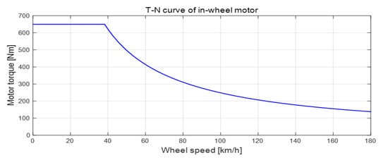
Figure 4.
Maximum IWM torque.
Additionally, as shown in Figure 5, the state of charge of the IWM battery can be charged with negative IWM torque during most regenerative braking [22,23]. To prevent overcharging of the IWM battery, it is recommended to strictly limit the maximum regenerative torque (negative limit value). Therefore, is asymmetrically smaller than in this IWM system. Finally, the maximum usable yaw moment was designed as:
where is the vehicle track width and is the effective tire radius, respectively. For safety reasons, the desired yaw moment was limited to the range .
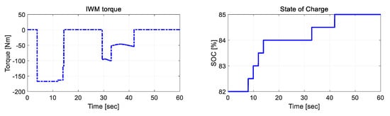
Figure 5.
State of charge of the IWM battery during regeneration braking.
4.2. WLS Allocation
To distribute the IWM torque to produce the actual yaw moment corresponding to , the proposed distribution method was applied to each front wheel. In the torque distribution between the two IWMs of the front wheels, only a positive IWM torque is desirable for operation in weak cornering situations (a large negative IWM torque at high wheel speeds can degrade IWM durability [3]). However, in severe cornering situations where a large amount of yaw moment is urgently needed, both positive IWM torque and negative IWM torque are available within the torque operating area. The optimal torque allocation based on the WLS method is introduced as follows [15]:
where and are the weight factors and and are the input constraints, respectively. Additionally, and .
5. Simulation Study
5.1. Simulation Environments
A simulation study was conducted to verify the superiority of the proposed control algorithm. The comparison was a PID feedback controller and a model-based controller with initial tire cornering stiffness , the structure of which is shown in Figure 6. The gain of the PID controller was zero (to effectively cancel that pole) at the same position on the open-loop system poles [4]. Therefore, the of the PID controller was designed as to offset the pole of the vehicle bicycle model. Thus, the PI gains and were set to and , respectively. The cutoff frequency was 0.7 Hz, where was the initial vehicle longitudinal speed.
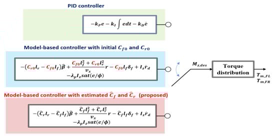
Figure 6.
Comparison targets in simulation.
Since the comparison target also accompanies the same torque distribution algorithm and reference model as the proposed control algorithm, the advantages of the proposed algorithm can be clearly confirmed by comparing with the comparison target. CarSim (vehicle dynamics software) and MATLAB/Simulink were utilized to implement the simulation. The simulation vehicle used was an E-class sedan with the parameters of the experimental vehicle (see Table 1). The powertrain architecture consisted of the IWM on the front wheels and the engine driving the rear wheels. The tire model used was a Magic Formula tire model [24,25]. The value of the tire-road friction coefficient of the test course was given as 0.9.

Table 1.
Specifications of the simulation vehicle.
5.2. Simulation Results
5.2.1. Comparison with the PID Controller
Compared to the PID feedback controller, the advantages of model-based control using the feedforward term can be seen. As shown in Figure 7, a circular rotation test was performed to evaluate the controller performance in steady-state cornering. Figure 7a shows the steering wheel angle and longitudinal speed command from the driver. It is important to note the vibration IWM torque output of the PID controller in Figure 7c,d. This output was due to oscillations in the feedback term along with the measurement noise of the yaw rate signal, low actuator bandwidth, and motor backlash effects in the IWM system. Since the vibration problem of the PID controller caused a large vehicle longitudinal jerk in steady-state cornering (at 6–12 s in Figure 7h), the driver’s riding comfort with this PID controller is expected to deteriorate significantly in real-car applications.
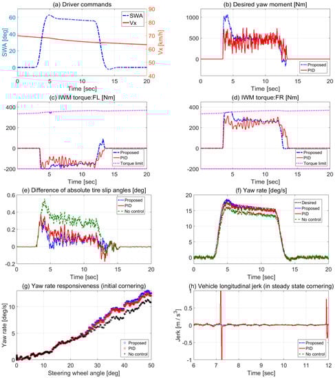
Figure 7.
Simulation results of circle turn test (vs. PID controller). (a) Driver commands. (b) Desired yaw moment. IWM torques: (c) FL, and (d) FR. (e) Difference in absolute tire slip angles. (f) Yaw rate. (g) Yaw rate responsiveness (in initial cornering). (h) Vehicle longitudinal jerk (in steady state cornering).
Additionally, from the smaller difference in the absolute tire slip angles and higher yaw rate responsiveness in the initial cornering (at (3−5) s in Figure 7e,g), it can be seen that the model-based control of the proposed algorithm exhibited neutral steering characteristics in the higher yaw rate responsiveness at the initial cornering. Finally, it showed improved control accuracy (see Figure 7f).
The advantages of model-based control compared to PID controllers can be summarized as follows: (1) Due to the feed-forward term, the proposed algorithm induces a smoother and larger IWM torque than the PID controller. In the case of the PID controller, if is increased to increase the desired yaw moment, the vibration torque is expected to become more severe. (2) The proposed algorithm exhibits higher lateral acceleration at the same steering command due to the larger in the initial cornering; this means that the proposed algorithm increases the vehicle’s cornering agility. In driving environments that require high cornering agility, such as fast lane changes, this benefit of model-based control with a feedforward term can be an even greater advantage.
5.2.2. Comparison with Model-Based Controller with the Initial
Figure 8 compares the model-based controller and initial in the circular rotation test. Figure 8b shows that the of the front axle became smaller than the of the rear axle. This confirms that the vehicle was driving in steady state cornering with a tendency to understeer. The model-based controller with the initial produced insufficient desired yaw moment and IWM torque compared to the proposed algorithm. 8a,c,d). This is because the imprecise feedforward term of does not reflect the real-time tendency of the vehicle to understeer at all. When the vehicle turns a corner on a slippery road surface, this incorrect feedforward term can cause dangerous vehicular lateral behavior that reduces vehicle stability. Otherwise, the proposed algorithm with an estimated produces the sufficient yaw moment and IWM torque desired due to the correct feedforward term. This comparative study can confirm that the proposed model-based controller with the accurate vehicle state estimation function induces neutral steering (small difference in absolute tire slip angle in Figure 8e). Table 2 summarizes the performance comparison of the controllers. The proposed controller was confirmed to have the most accurate control accuracy and the highest yaw rate response.
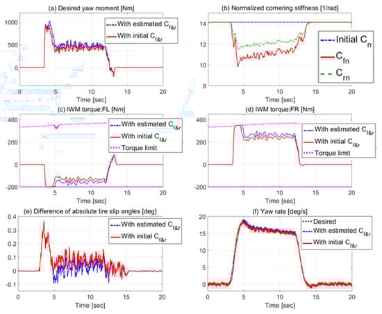
Figure 8.
Simulation results of circle turn test (vs. model-based controller with initial ). (a) Desired yaw moment. (b) Normalized cornering stiffness. IWM torques: (c) FL, and (d) FR. (e) Difference of absolute tire slip angles. (f) Yaw rate.
Table 2.
Comparison of controllers (simulation results).
5.2.3. Comparison According to Different Weight Factors in WLS Allocation
The controller is the proposed model-based controller with an estimated . As in the previous circular test, Figure 9a,b show steering and longitudinal speed commands, respectively. Therefore, we checked how the simulation results changed as the weight changed in the WLS allocation method. The value proposed in this paper was 150, and the comparison target was the case where and .
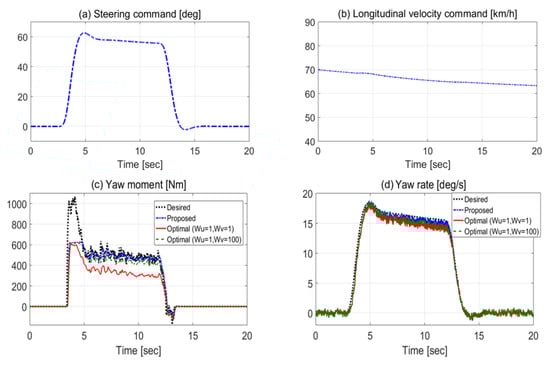
Figure 9.
Simulation results of circle turn test (according to different : (150 (proposed), 100, 1). (a) Steering command. (b) Longitudinal velocity command. (c) Yaw moment. (d) Yaw rate.
An optimal WLS assignment with produced a smaller IWM torque than the proposed WLS assignment with . This produced an actual yaw moment that was much smaller than the desired yaw moment (see Figure 9c). Additionally, the actual yaw rate in Figure 9d was much smaller than the desired yaw rate. An optimal torque allocation with weight of 100 was implemented to increase the actual yaw moment. However, this also produced a smaller actual yaw moment than the proposed WLS assignment with .
Table 3 shows that the proposed WLS allocation method with had a very high control accuracy of the yaw rate through the accurate generation of the actual yaw moment.
Table 3.
Comparison of allocation methods (simulation results).
6. Conclusions
In this paper, we proposed a new vehicle lateral motion controller using IWM. To overcome the limitations of existing studies that do not consider the practical problem of the high-gain feedback control term, we designed a model-based controller based on tire cornering stiffness estimation that actively utilizes the feedforward control term. This controller follows the yaw rate criterion with neutral steering characteristics, which improves cornering agility.
Through a simulation study on the high friction surface, it was confirmed that some evaluation factors were improved in terms of cornering performance compared to the conventional PID control algorithm. The main differences between the existing studies and the proposed lateral motion controller can be summarized as follows: (1) The feedforward term, including the tire cornering stiffness value estimated during the design process, improves vehicle cornering performance. (2) The WLS allocation method optimally distributes the IWM torque with consideration to the torque operating area. (3) Due to the simple structure of the proposed control algorithm, it has high real-vehicle applicability.
Due to the high practicality of the proposed control algorithm, it is expected to be easily applied to IWM-equipped vehicles for mass production in the near future. Additionally, the proposed mode-based control technique is fully applicable to the development of other chassis logics such as electronic stability control systems, anti-lock braking systems, and traction control systems.
Funding
This research was funded by a “Regional Innovation Strategy (RIS)” grant through the National Research Foundation of Korea (NRF), funded by the Ministry of Education (MOE) (2021RIS-003); a Korea Institute for Advancement of Technology (KIAT) grant funded by the Korea Government (MOTIE) (P0012769, The Competency Development Program for Industry Specialist); and a National Research Foundation of Korea (NRF) grant funded by the Korea government (MSIT) (No. 2022-0795).
Conflicts of Interest
The author declares no conflict of interest.
References
- Visconti, A.; Cavanna, M. Method for Controlling the Side Slip Angle of a Rear-Wheel Drive Vehicle when Turning. U.S. Patent 8463498, 11 June 2013. [Google Scholar]
- Fallah, M.S.; Khajepour, A.; Fidan, B.; Chen, S.; Litkouhi, B. Controller Development Using Optimal Torque Distribution for Driver Handling Assistance. In Proceedings of the 2012 American Control Conference (ACC), Montreal, Canada, 27–29 June 2012; pp. 2910–2915. [Google Scholar]
- Murata, S. Innovation by in-wheel-motor drive unit. Veh. Sys. Dyn. 2012, 50, 807–830. [Google Scholar] [CrossRef]
- Park, G. Vehicle Sideslip Angle Estimation Based on Interacting Multiple Model Kalman Filter Using Low-Cost Sensor Fusion. IEEE Trans. Veh. Technol. 2022, 71, 6088–6099. [Google Scholar] [CrossRef]
- Park, G.; Choi, S.B. A Model Predictive Control for Path Tracking of Electronic-Four-Wheel Drive Vehicles. IEEE Trans. Veh. Technol. 2021, 70, 11352–11364. [Google Scholar] [CrossRef]
- Han, K.; Choi, M.; Lee, B.; Choi, S.B. Development of a Traction Control System Using a Special Type of Sliding Mode Controller for Hybrid 4WD Vehicles. IEEE Trans. Veh. Technol. 2018, 67, 264–274. [Google Scholar] [CrossRef]
- Novellis, L.; Sorniotti, A.; Gruber, P. Wheel Torque Distribution Criteria for Electric Vehicles with Torque-Vectoring Differentials. IEEE Trans. Veh. Technol. 2014, 63, 1593–1602. [Google Scholar] [CrossRef]
- Lu, Q.; Gentile, P.; Tota, A.; Sorniotti, A.; Gruber, P.; Costamagna, F.; Smet, J. Enhancing vehicle cornering limit through sideslip and yaw rate control. Mech. Syst. Signal Process. 2016, 75, 455–472. [Google Scholar] [CrossRef]
- Goggia, T.; Sorniotti, A.; Novellis, L.; Ferrara, A.; Gruber, P.; Theunissen, J.; Steenbeke, D.; Knauder, B.; Zehetner, J. Integral Sliding Mode for the Torque-Vectoring Control of Fully Electric Vehicles: Theoretical Design and Experimental Assessment. IEEE Trans. Veh. Technol. 2015, 64, 1701–1715. [Google Scholar] [CrossRef]
- Fallah, M.S.; Khajepour, A.; Fidan, B.; Chen, S.; Litkouhi, B. Vehicle Optimal Torque Vectoring Using State-Derivative Feedback and Linear Matrix Inequality. IEEE Trans. Veh. Technol. 2013, 62, 1540–1552. [Google Scholar] [CrossRef]
- Kasinathan, D.; Kasaiezadeh, A.; Wong, A.; Khajepour, A.; Che, S.; Litkouhi, B. An Optimal Torque Vectoring Control for Vehicle Applications via Real-Time Constraints. IEEE Trans. Veh. Technol. 2016, 65, 4368–4378. [Google Scholar] [CrossRef]
- Khosravani, S.; Kasaiezadeh, A.; Khajepour, A.; Fidan, B.; Chen, S.; Litkouhi, B. Torque-Vectoring-Based Vehicle Control Robust to Driver Uncertainties. IEEE Trans. Veh. Technol. 2015, 64, 3359–3367. [Google Scholar] [CrossRef]
- Hindiyeh, R.; Gerdes, J. A Controller Framework for Autonomous Drifting: Design, Stability, and Experimental Validation. ASME J. Dyn. Syst. Meas. Control 2014, 136, 051015. [Google Scholar] [CrossRef]
- Coser, C.; Hindiyeh, R.; Gerdes, J. Analysis and control of high sideslip manoeuvres. Veh. Syst. Dyn. 2010, 48, 317–336. [Google Scholar]
- Park, G.; Choi, S.B. Optimal Brake Distribution for Electronic Stability Control Using Weighted Least Square Allocation Method. In Proceedings of the 2016 16th International Conference on Control, Automation and Systems (ICCAS), Gyeongju, Korea, 16–19 October 2016; pp. 1420–1425. [Google Scholar]
- Oh, J.; Choi, S.B. Vehicle Velocity Observer Design Using 6-D IMU and Multiple-observer Approach. IEEE Trans. Intell. Transport. Syst. 2012, 13, 1865–1879. [Google Scholar] [CrossRef]
- Park, G. Sideslip Angle Control of Electronic-Four-Wheel Drive Vehicle Using Backstepping Controller. Int. J. Automot. Technol. 2022, 23, 727–737. [Google Scholar] [CrossRef]
- Piyabongkarn, D.; Rajamani, R.; Grogg, J.; Lew, J. Development and Experimental Evaluation of a Slip Angle Estimator for Vehicle Stability Control. IEEE Trans. Control Syst. Technol. 2009, 17, 78–88. [Google Scholar] [CrossRef]
- Park, G.; Choi, S.B.; Hyun, D.; Lee, J. Integrated Observer Approach Using In-vehicle Sensors and GPS for Vehicle State Estimation. Mechatronics 2018, 50, 134–147. [Google Scholar] [CrossRef]
- Khalil, H.K. Performance recovery under output feedback sampled-data stabilization of a class of nonlinear systems. IEEE Trans. Autom. Control 2004, 49, 2173–2184. [Google Scholar] [CrossRef]
- Han, K.; Nguyen, T.W.; Nam, K. Battery Energy Management of Autonomous Electric Vehicles Using Computationally Inexpensive Model Predictive Control. Electronics 2020, 9, 1277. [Google Scholar] [CrossRef]
- Chen, Y.; Li, X.; Wiet, C.; Wang, J. Energy Management and Driving Strategy for In-Wheel Motor Electric Ground Vehicles with Terrain Profile Preview. IEEE Trans. Ind. Inform. 2014, 10, 1938–1947. [Google Scholar] [CrossRef]
- Chen, J.; Xu, C.; Wu, C.; Xu, W. Adaptive Fuzzy Logic Control of Fuel-Cell-Battery Hybrid Systems for Electric Vehicles. IEEE Trans. Ind. Inform. 2018, 14, 292–300. [Google Scholar] [CrossRef]
- Gipser, M. FTire—The tire simulation model for all applications related to vehicle dynamics. Veh. Syst. Dyn. 2007, 45, 139–151. [Google Scholar] [CrossRef]
- Park, G.; Han, K.; Nam, K.; Kim, H.; Choi, S.B. Torque Vectoring Algorithm of Electronic-Four-Wheel Drive Vehicles for Enhancement of Cornering Performance. IEEE Trans. Veh. Technol. 2020, 69, 3668–3679. [Google Scholar] [CrossRef]
Publisher’s Note: MDPI stays neutral with regard to jurisdictional claims in published maps and institutional affiliations. |
© 2022 by the author. Licensee MDPI, Basel, Switzerland. This article is an open access article distributed under the terms and conditions of the Creative Commons Attribution (CC BY) license (https://creativecommons.org/licenses/by/4.0/).