
Development of Reactive Power Allocation Method for Radial Structure Wind Farm Considering Multiple Connections


Abstract
:1. Introduction
2. Framework for Reactive Power Dispatch
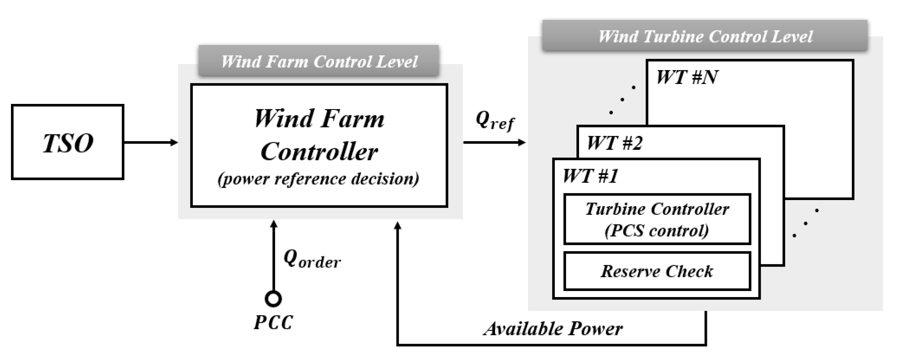
2.1. Hierarchical Control
2.2. Reactive Power Dispatch Methodology
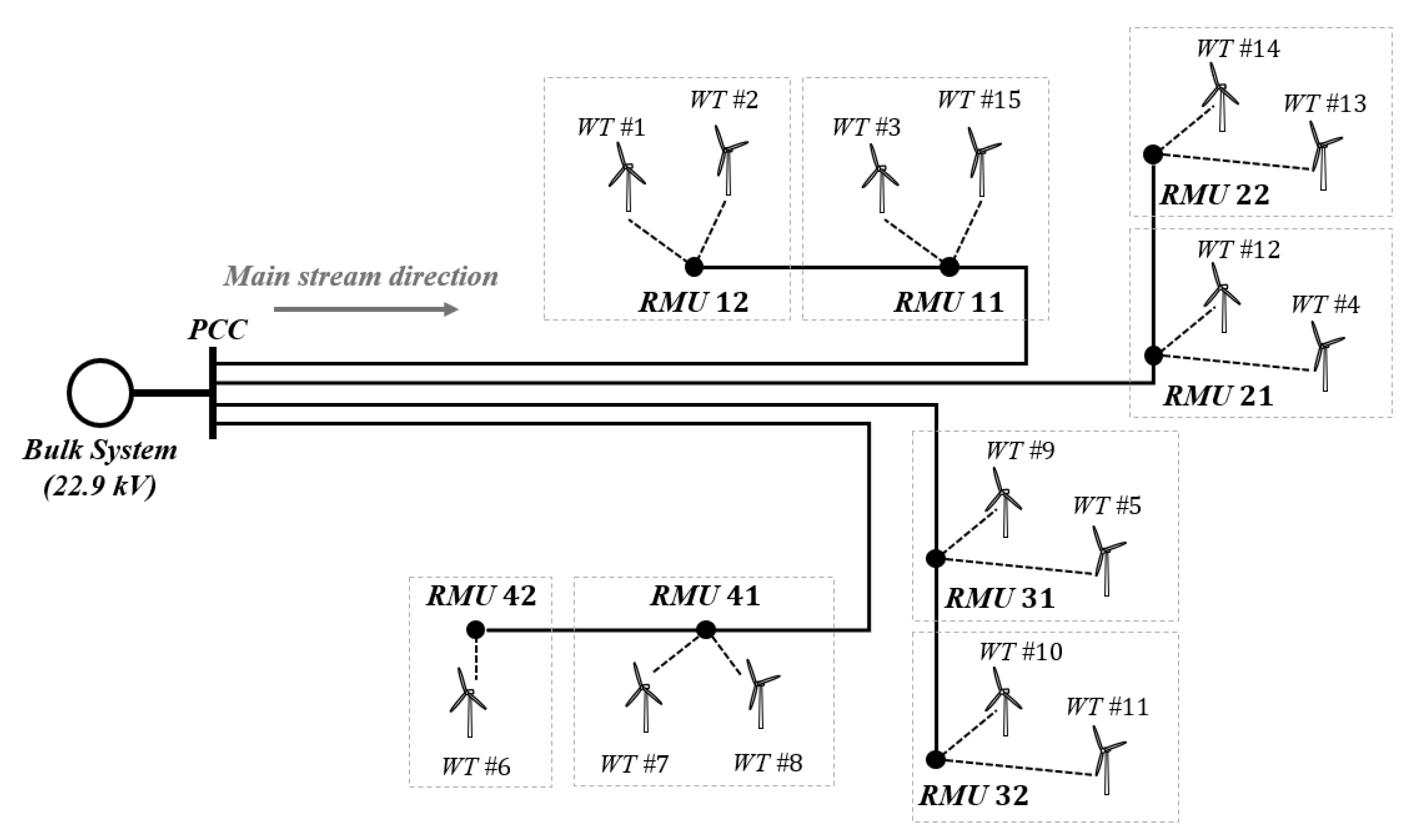
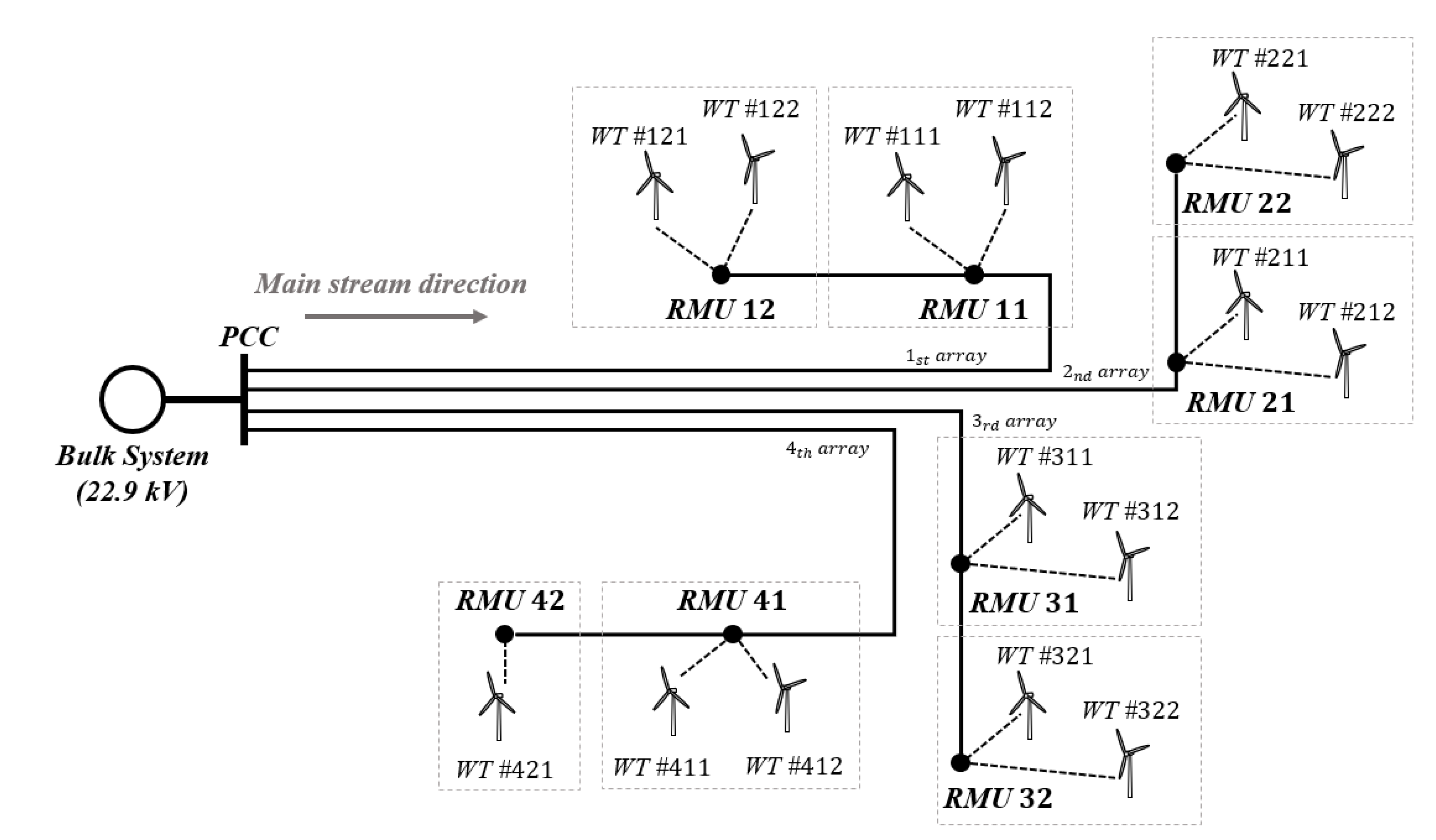
2.3. Dongbok Wind Farm
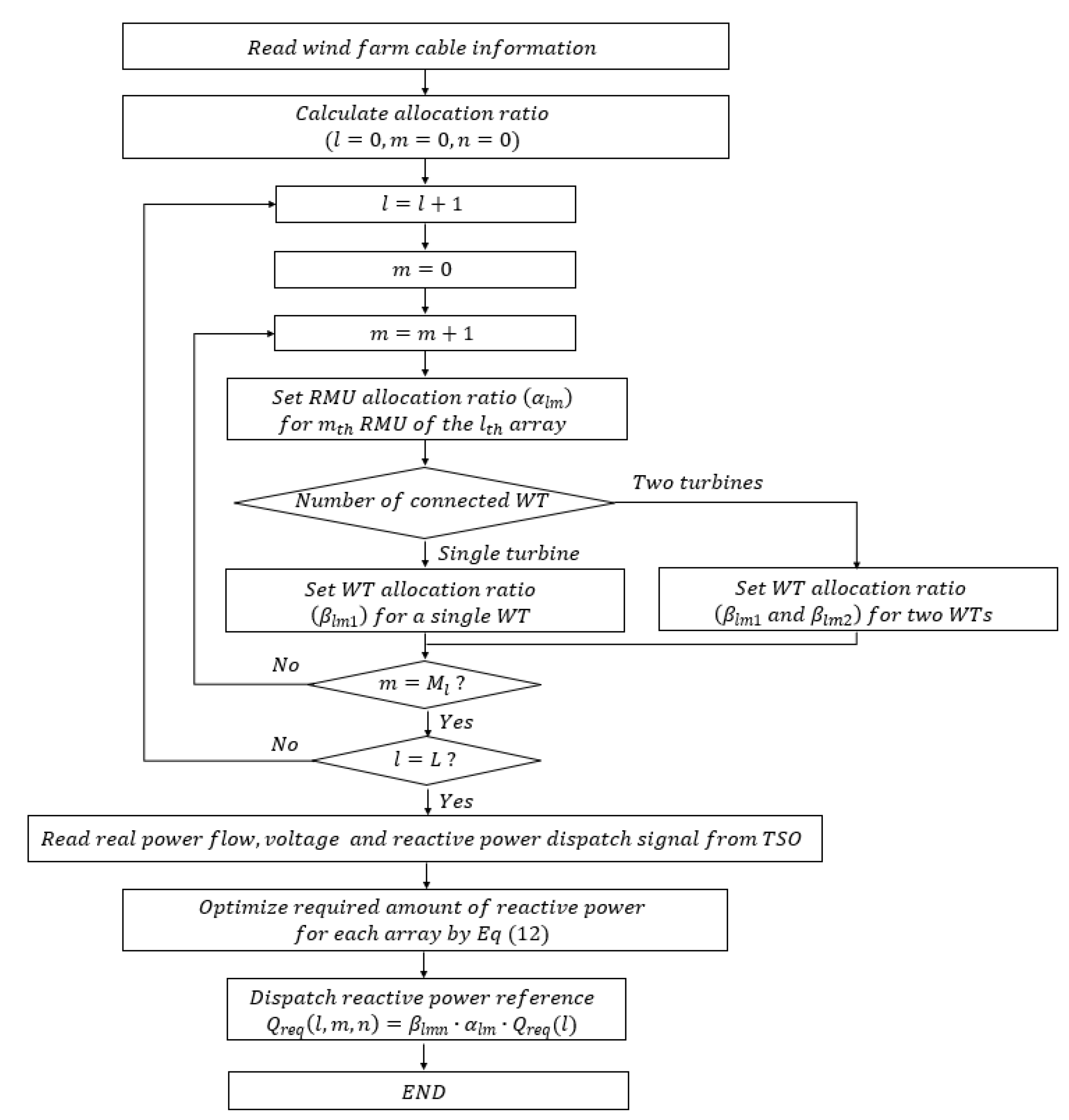
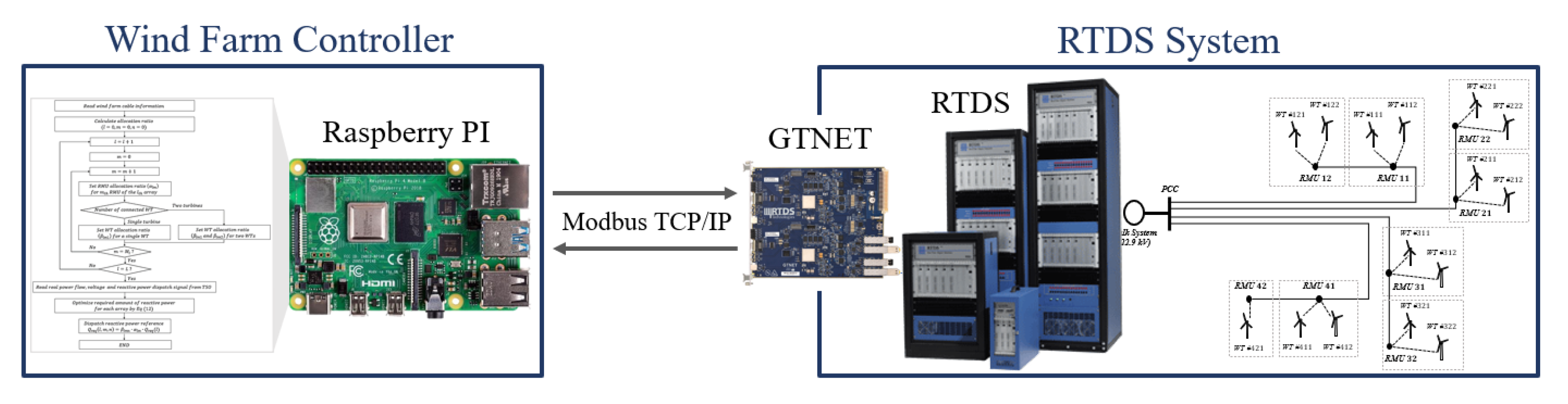
3. Algorithm Configuration
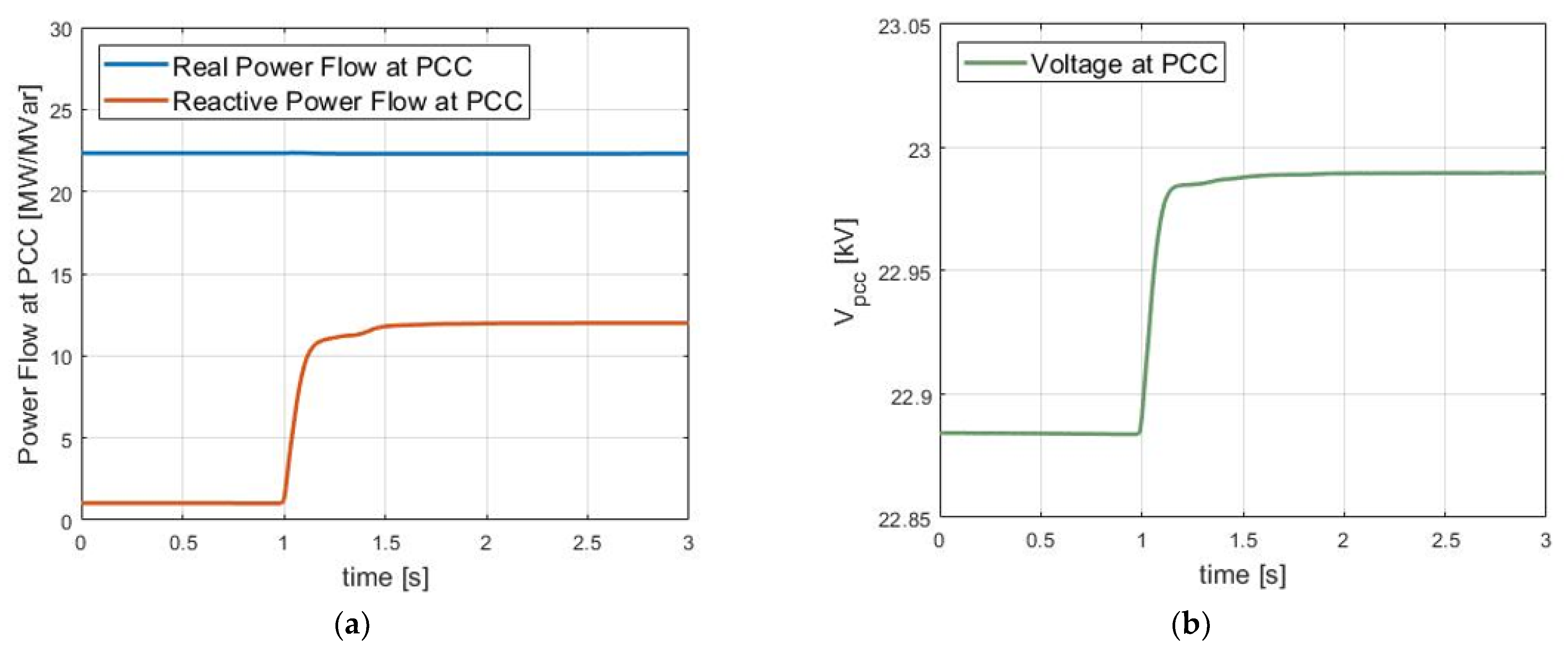
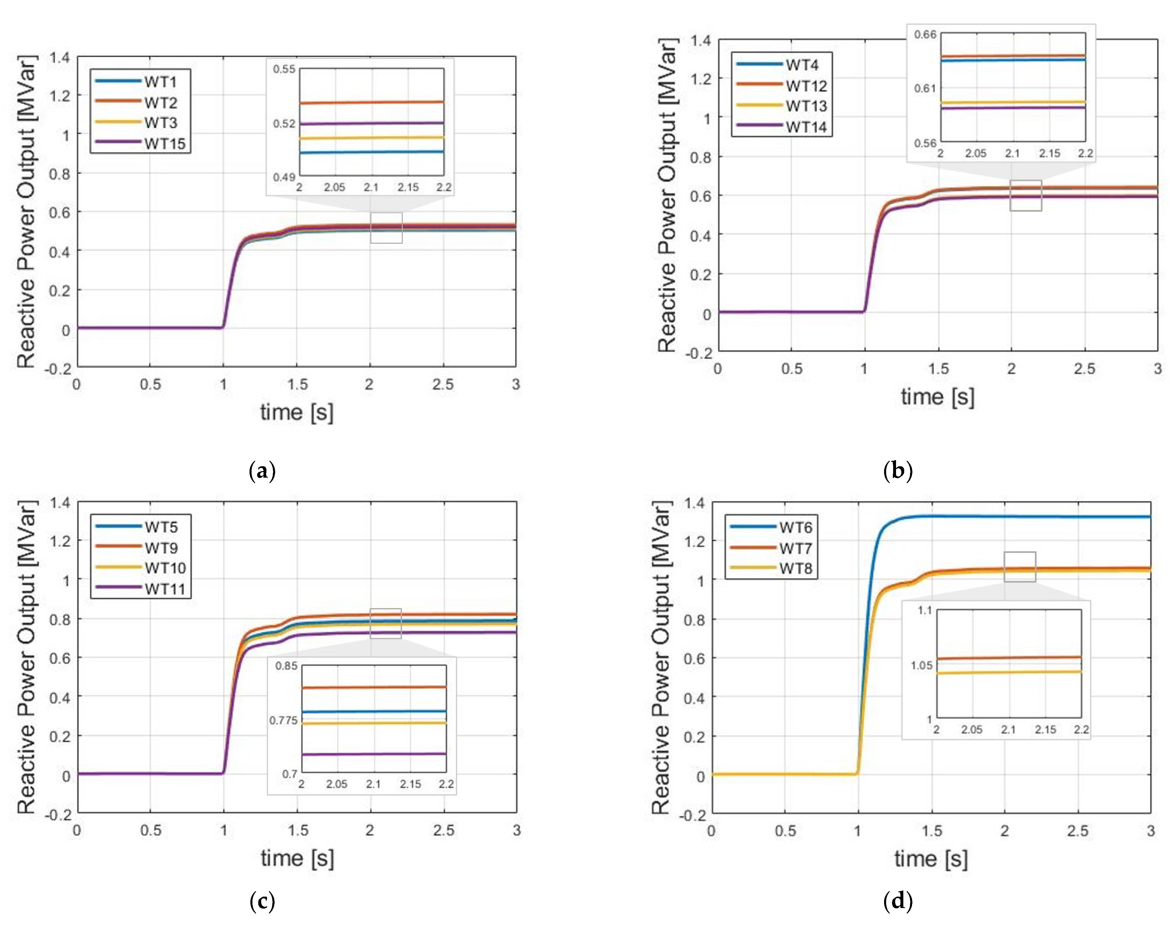
4. Simulation Results
5. Conclusions
Author Contributions
Funding
Conflicts of Interest
Nomenclature
| Reactive power reserve of wind turbine | |
| Converter capacity of wind turbine | |
| Active power of wind turbine | |
| Reactive power reference for wind turbine | |
| Reactive power reference from TSO for the entire wind farm | |
| Power loss in wind farm | |
| Power loss in the wind farm cable | |
| Cable resistance | |
| Line resistance between RMUs | |
| Resistance of cable connected between RMU and wind turbine | |
| Allocation ratio for wind turbine | |
| Line resistance between the RMU and the RMU | |
| Line resistance between the RMU and the connected wind turbine | |
| Allocation ratio for wind turbine connected to the RMU | |
| Reconfigured resistance consisting of | |
| Reconfigured resistance consisting of , and | |
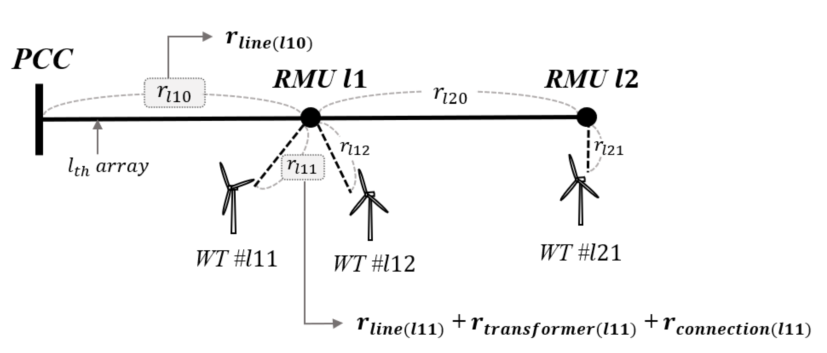
| line resistance between the RMU and the RMU in the array | |
| line resistance between the RMU and the wind turbine connected to the RMU in the array | |
| line resistance between the RMU and the wind turbine connected to the RMU in the array | |
| line resistance by connection height of the wind turbine connected to the RMU in the array | |
| RMU allocation ratio for the RMU in the array | |
| Wind turbine allocation ratio for the for the wind turbine connected to the RMU in the array | |
| Reactive power required at the array | |
| Reactive power required at the RMU in the array | |
| Reactive power required for the wind turbine connected to the RMU in the array | |
| Reactive power loss between the RMU and the wind turbine connected to the RMU | |
| Reactive power required for the wind turbine connected to the RMU in the array considering reactive power loss | |
| Measured value of active power flow at the RMU in the array |
References
- Kusiak, A.; Zheng, H.; Song, Z. Short-Term Prediction of Wind Farm Power: A Data Mining Approach. IEEE Trans. Energy Convers. 2009, 24, 125–136. [Google Scholar] [CrossRef]
- Sideratos, G.; Hatziargyriou, N.D. An Advanced Statistical Method for Wind Power Forecasting. IEEE Trans. Power Syst. 2007, 22, 258–265. [Google Scholar] [CrossRef]
- Tautz-Weinert, J.; Watson, S. Using SCADA data for wind turbine condition monitoring—A review. IET Renew. Power Gener. 2016, 11, 382–394. [Google Scholar] [CrossRef] [Green Version]
- Huang, S.; Wu, Q.; Bao, W.; Hatziargyriou, N.D.; Ding, L.; Rong, F. Hierarchical Optimal Control for Synthetic Inertial Response of Wind Farm Based on Alternating Direction Method of Multipliers. IEEE Trans. Sustain. Energy 2020, 12, 25–35. [Google Scholar] [CrossRef]
- Cui, H.; Li, X.; Wu, G.; Song, Y.; Liu, X.; Luo, D. MPC Based Coordinated Active and Reactive Power Control Strategy of DFIG Wind Farm with Distributed ESSs. Energies 2021, 14, 3906. [Google Scholar] [CrossRef]
- The Grid Code (Issue 5, Revision 18). Available online: https://www.nationalgrid.com/ (accessed on 20 June 2022).
- Revel, G.; Leon, A.E.; Alonso, D.M.; Moiola, J.L. Dynamics and Stability Analysis of a Power System With a PMSG-Based Wind Farm Performing Ancillary Services. IEEE Trans. Circuits Syst. I Regul. Pap. 2014, 61, 2182–2193. [Google Scholar] [CrossRef]
- Shi, X.; Cao, Y.; Shahidehpour, M.; Li, Y.; Wu, X.; Li, Z. Data-Driven Wide-Area Model-Free Adaptive Damping Control with Communication Delays for Wind Farm. IEEE Trans. Smart Grid 2020, 11, 5062–5071. [Google Scholar] [CrossRef]
- Nan, J.; Yao, W.; Wen, J.; Peng, Y.; Fang, J.; Ai, X.; Wen, J. Wide-area power oscillation damper for DFIG-based wind farm with communication delay and packet dropout compensation. Int. J. Electr. Power Energy Syst. 2020, 124, 106306. [Google Scholar] [CrossRef]
- Mitra, A.; Chatterjee, D. Active Power Control of DFIG-Based Wind Farm for Improvement of Transient Stability of Power Systems. IEEE Trans. Power Syst. 2015, 31, 82–93. [Google Scholar] [CrossRef]
- Guo, Y.; Gao, H.; Wu, Q.; Østergaard, J.; Yu, D.; Shahidehpour, M. Distributed coordinated active and reactive power control of wind farms based on model predictive control. Int. J. Electr. Power Energy Syst. 2019, 104, 78–88. [Google Scholar] [CrossRef] [Green Version]
- Yoon, D.H.; Song, H.; Jang, G.; Joo, S.K. Smart operation of HVDC systems for large penetration of wind energy re-sources. IEEE Trans. Smart Grid. 2013, 4, 359–366. [Google Scholar] [CrossRef]
- Huang, S.; Wu, Q.; Liao, W.; Wu, G.; Li, X.; Wei, J. Adaptive Droop-Based Hierarchical Optimal Voltage Control Scheme for VSC-HVdc Connected Offshore Wind Farm. IEEE Trans. Ind. Inform. 2021, 17, 8165–8176. [Google Scholar] [CrossRef]
- Mehrabankhomartash, M.; Saeedifard, M.; Yazdani, A. Adjustable Wind Farm Frequency Support Through Multi-Terminal HVDC Grids. IEEE Trans. Sustain. Energy 2021, 12, 1461–1472. [Google Scholar] [CrossRef]
- Wu, X.; Wang, M.; Shahidehpour, M.; Feng, S.; Chen, X. Model-Free Adaptive Control of STATCOM for SSO Mitigation in DFIG-Based Wind Farm. IEEE Trans. Power Syst. 2021, 36, 5282–5293. [Google Scholar] [CrossRef]
- Photovoltaics, D.G.; Storage, E. IEEE standard for interconnection and interoperability of distributed energy resources with associated electric power systems interfaces. IEEE Std 2018, 1547, 1547–2018. [Google Scholar]
- Desk Study on Technical Gaps of Country-Specific Grid Codes and Regulations and Recommendation for a Common Asean Wide-Grid Code, USAID. 2021. Available online: https://pdf.usaid.gov/pdf_docs/PA00XVJB.pdf (accessed on 20 June 2022).
- Wang, N.; Li, J.; Hu, W.; Zhang, B.; Huang, Q.; Chen, Z. Optimal reactive power dispatch of a full-scale converter based wind farm considering loss minimization. Renew. Energy 2019, 139, 292–301. [Google Scholar] [CrossRef]
- Sharaf, H.M.; Zeineldin, H.H.; El-Saadany, E. Protection Coordination for Microgrids with Grid-Connected and Islanded Capabilities Using Communication Assisted Dual Setting Directional Overcurrent Relays. IEEE Trans. Smart Grid 2016, 9, 143–151. [Google Scholar] [CrossRef]
- Zamani, M.A.; Yazdani, A.; Sidhu, T.S. A Communication-Assisted Protection Strategy for Inverter-Based Medium-Voltage Microgrids. IEEE Trans. Smart Grid 2012, 3, 2088–2099. [Google Scholar] [CrossRef]
- Zhang, B.; Hu, W.; Hou, P.; Tan, J.; Soltani, M.; Chen, Z. Review of Reactive Power Dispatch Strategies for Loss Minimization in a DFIG-based Wind Farm. Energies 2017, 10, 856. [Google Scholar] [CrossRef] [Green Version]
- Zhang, B.; Hou, P.; Hu, W.; Soltani, M.; Chen, C.; Chen, Z. A Reactive Power Dispatch Strategy With Loss Minimization for a DFIG-Based Wind Farm. IEEE Trans. Sustain. Energy 2016, 7, 914–923. [Google Scholar] [CrossRef]
- Lu, Y.; Tomsovic, K. Wide area hierarchical voltage control to improve security margin for systems with high wind pen-etration. IEEE Trans. Power Syst. 2018, 33, 6218–6228. [Google Scholar] [CrossRef]
- Zhou, D.; Blaabjerg, F.; Lau, M.; Tonnes, M. Thermal Behavior Optimization in Multi-MW Wind Power Converter by Reactive Power Circulation. IEEE Trans. Ind. Appl. 2013, 50, 433–440. [Google Scholar] [CrossRef] [Green Version]
- Tan, H.; Li, H.; Yao, R.; Zhou, Z.; Liu, R.; Wang, X.; Zheng, J. Reactive-voltage coordinated control of offshore wind farm considering multiple optimization objectives. Int. J. Electr. Power Energy Syst. 2021, 136, 107602. [Google Scholar] [CrossRef]
- Huang, S.; Li, P.; Wu, Q.; Li, F.; Rong, F. ADMM-based distributed optimal reactive power control for loss minimization of DFIG-based wind farms. Int. J. Electr. Power Energy Syst. 2020, 118, 105827. [Google Scholar] [CrossRef]
- Liu, Y.; Ćetenović, D.; Li, H.; Gryazina, E.; Terzija, V. An optimized multi-objective reactive power dispatch strategy based on improved genetic algorithm for wind power integrated systems. Int. J. Electr. Power Energy Syst. 2021, 136, 107764. [Google Scholar] [CrossRef]
- Xiao, Y.; Wang, Y.; Sun, Y. Reactive Power Optimal Control of a Wind Farm for Minimizing Collector System Losses. Energies 2018, 11, 3177. [Google Scholar] [CrossRef] [Green Version]
- Jung, S.; Jang, G. A Loss Minimization Method on a Reactive Power Supply Process for Wind Farm. IEEE Trans. Power Syst. 2016, 32, 3060–3068. [Google Scholar] [CrossRef]
- Yoo, Y.; Jung, S.; Song, S.; Suh, J.; Lee, J.; Jang, G. Development of practical allocation method for reactive power reference for wind farms through inner-voltage restriction. IET Gener. Transm. Distrib. 2022, 16, 3069–3079. [Google Scholar] [CrossRef]
- Vargas, L.S.; Bustos-Turu, G.; Larrain, F. Wind Power Curtailment and Energy Storage in Transmission Congestion Management Considering Power Plants Ramp Rates. IEEE Trans. Power Syst. 2014, 30, 2498–2506. [Google Scholar] [CrossRef]
- Prajapati, V.K.; Mahajan, V.; Padhy, N.P. Congestion management of integrated transmission and distribution network with RES and ESS under stressed condition. Int. Trans. Electr. Energy Syst. 2021, 31, e12757. [Google Scholar] [CrossRef]
- Wind-Turbine-Models.com, Hanjin HJWT2000/87. Available online: https://en.wind-turbine-models.com/turbines/1157-hanjin-hjwt2000-87#datasheet (accessed on 20 June 2022).


| From | To |
Cable SQMM |
Length | XL | C | R | L |
|---|---|---|---|---|---|---|---|
| 1 | RMU1 | 60 | 0.374 | 0.0651 | 0.0785 | 0.1459 | 0.1726 |
| 2 | RMU1 | 60 | 0.08 | 0.0139 | 0.0168 | 0.0312 | 0.0369 |
| RMU1 | RMU2 | 100 | 0.061 | 0.0099 | 0.014 | 0.0143 | 0.0262 |
| 3 | RMU2 | 60 | 0.357 | 0.0621 | 0.075 | 0.1392 | 0.1648 |
| 15 | RMU2 | 60 | 0.27 | 0.0470 | 0.0567 | 0.1053 | 0.1246 |
| RMU2 | PCC | 200 | 4.57 | 0.6718 | 1.4624 | 0.5438 | 1.782 |
| 14 | RMU3 | 60 | 0.261 | 0.0454 | 0.0548 | 0.1018 | 0.1205 |
| 13 | RMU3 | 60 | 0.21 | 0.0365 | 0.0441 | 0.0819 | 0.0969 |
| RMU3 | RMU4 | 100 | 0.297 | 0.0481 | 0.0683 | 0.0695 | 0.1276 |
| 4 | RMU4 | 60 | 0.203 | 0.0353 | 0.0426 | 0.0792 | 0.0937 |
| 12 | RMU4 | 60 | 0.17 | 0.0296 | 0.0357 | 0.0663 | 0.0785 |
| RMU4 | PCC | 200 | 3.83 | 0.0563 | 1.2256 | 0.4558 | 1.4934 |
| 11 | RMU5 | 60 | 0.57 | 0.0992 | 0.1197 | 0.2223 | 0.2631 |
| 10 | RMU5 | 60 | 0.226 | 0.0393 | 0.0475 | 0.0881 | 0.1043 |
| RMU5 | RMU6 | 100 | 0.173 | 0.028 | 0.0398 | 0.0405 | 0.0743 |
| 5 | RMU | 60 | 0.307 | 0.0535 | 0.0645 | 0.1197 | 0.1417 |
| 9 | RMU6 | 60 | 0.082 | 0.0143 | 0.0172 | 0.032 | 0.0379 |
| RMU6 | PCC | 200 | 3.01 | 0.4425 | 0.9632 | 0.3582 | 1.1737 |
| 6 | RMU7 | 60 | 0.24 | 0.0418 | 0.0504 | 0.0936 | 0.1108 |
| RMU7 | RMU8 | 100 | 0.326 | 0.0528 | 0.075 | 0.0763 | 0.1401 |
| 8 | RMU8 | 60 | 0.21 | 0.0365 | 0.0441 | 0.0819 | 0.0969 |
| 7 | RMU8 | 60 | 0.142 | 0.0247 | 0.0298 | 0.0554 | 0.0655 |
| RMU8 | PCC | 200 | 2.54 | 0.3734 | 0.8128 | 0.3023 | 0.9904 |
| Simulated Control Methods | PD (Proportional Distribution), Proposed Method with Reactive Power Capacity Limit (See Equation (1)) |
|---|---|
| Reactive power requirement | 4, 6, 8, 10, 12, 14, 16 [MVAr] |
| Active power profile | 1.5 [MW] × 15 = 22.5 [MW] |
| Simulation time | 3 [s] |
| Dispatch time | 1 [s] |
| 4 | 6 | 8 | 10 | 12 | 14 | 16 | |
|---|---|---|---|---|---|---|---|
| (PD) Average profile [MW] | 22.33672 | 22.33158 | 22.32402 | 22.31396 | 22.30148 | 22.28656 | 22.26916 |
| (Proposed) Average profile [MW] | 22.33684 | 22.33183 | 22.32438 | 22.31460 | 22.30259 | 22.28850 | 22.27145 |
| Loss reduction amount [kW] | 0.12 | 0.25 | 0.36 | 0.64 | 1.11 | 1.94 | 2.29 |
Publisher’s Note: MDPI stays neutral with regard to jurisdictional claims in published maps and institutional affiliations. |
© 2022 by the authors. Licensee MDPI, Basel, Switzerland. This article is an open access article distributed under the terms and conditions of the Creative Commons Attribution (CC BY) license (https://creativecommons.org/licenses/by/4.0/).
Share and Cite
Yoo, D.; Kang, S.; Jang, G.; Jung, S. Development of Reactive Power Allocation Method for Radial Structure Wind Farm Considering Multiple Connections. Electronics 2022, 11, 2176. https://doi.org/10.3390/electronics11142176
Yoo D, Kang S, Jang G, Jung S. Development of Reactive Power Allocation Method for Radial Structure Wind Farm Considering Multiple Connections. Electronics. 2022; 11(14):2176. https://doi.org/10.3390/electronics11142176
Chicago/Turabian StyleYoo, Deokki, Sungwoo Kang, Gilsoo Jang, and Seungmin Jung. 2022. "Development of Reactive Power Allocation Method for Radial Structure Wind Farm Considering Multiple Connections" Electronics 11, no. 14: 2176. https://doi.org/10.3390/electronics11142176
APA StyleYoo, D., Kang, S., Jang, G., & Jung, S. (2022). Development of Reactive Power Allocation Method for Radial Structure Wind Farm Considering Multiple Connections. Electronics, 11(14), 2176. https://doi.org/10.3390/electronics11142176