1. Introduction
With the application of high-power frequency-using equipment and electromagnetic pulse (EMP) weapons, the battlefield electromagnetic environment becomes increasingly complicated. Such an environment tends to cause interference or even damage to the weapons and equipment, and cable circuits are one of the most easily coupled channels for interference. To adapt to the battlefield electromagnetic environment better, it is necessary to perform the HIRF RS test in the cable circuit coupling channel. In MIL-STD-464C, the shipboard operations and the ordnance are subjected to an average electric field intensity of 270 V/m from 150 MHz to 225 MHz. For peak field intensity, it can even reach 3210 V/m [
1]. Nevertheless, in laboratory conditions, it is very difficult to realize such a high-field-intensity electromagnetic radiation environment in a large-scale space [
2,
3,
4]. At times, it cannot achieve the desired results even if a lot of humanpower and material resources are consumed. Therefore, it is urgent to find a method that can replace the HIRF RS test.
Replacing the HIRF electromagnetic radiation test with the bulk current injection (BCI) method provides a way to solve the above problem [
5,
6]. The research on the equivalent test method of the cable coupling channel using BCI has made some progress [
7,
8]. In the unshielded two-wire circuit systems, the equipment under test (EUT) at both ends needs to be assessed simultaneously on many occasions. Nevertheless, the EUT is usually the nonlinear system, and its impedance characteristics are transformed with a change in field intensity. If the method of double bulk current injection (DBCI) [
9,
10] replacing HIRF electromagnetic radiation can eliminate the influence of the EUT impedance at both ends, the problem that the EUT is a nonlinear termination can be solved.
The manuscript organization is as follows:
Section 2 calculates the response of the EUT at both ends in radiation and injection conditions, and derives the linear corresponding relationship between the two injected excitation sources and the radiation field intensity.
Section 3 puts forward the test method of DBCI replacing high-field-intensity radiation. In
Section 4, the simulation verification is carried out through CST. In
Section 5, the tests of the passing-through load are performed to verify the method at the unit level.
Section 6 draws conclusions.
2. Theoretical Model
In fact, although common mode (CM)/differential mode(DM)circuits are coupled at the terminations and theoretically require simultaneous solution, it will be shown that the assumption of a weak imbalance allows one to first solve the modal circuit related to the dominant effect, by ignoring the back-interaction due to voltages/currents induced into the secondary-mode circuit, and second, to represent mode conversion into the secondary-mode circuit by means of dependent sources controlled by the modal voltages induced at the terminations of the primary network through the degree of imbalance of each termination [
11].
The unshielded two-wire circuit system is shown in
Figure 1. The height of the two-wire circuit system from the ground is
H and the length is
L.
ZC is the characteristic impedance of the cable. The two current probes are stuck on the cable. In the circuit, the current probe appears as the loading impedance (
ZP) and the loading admittance (
YP) coupled to the cable [
12,
13,
14,
15].
Due to the imbalance of the terminal, the CM interference generated on the cable circuit will be converted into the DM interference [
16]. In most cases, the DM interference has the greatest impact on the equipment. In practical engineering, the two transmission lines are very close together. In the case of the far field, the distance between the two transmission lines can be neglected. Under injection conditions, the positions of the two transmission lines are relatively symmetrical to the probe. Therefore, the CM loop of the two transmission lines is identical under both conditions.
2.1. CM Response under Injection Conditions
The CM circuit in injection conditions is shown in
Figure 2.
VS1 and
VS2 are the CM voltage coupled to the cable circuit by the probe 1 and probe 2 respectively.
ZP expresses the impedance coupled to the wire, and
YP represents the admittance coupled to the wire.
ZC,L and
ZC,R are the CM impedance of the EUT at both ends respectively.
Vcm and
Icm are the CM voltage and the CM current respectively. The superscript (i) indicates the injection conditions.
It can be calculated that the CM responses of the EUT at both ends under the injection conditions are:
The specific expressions of (1) and (2) are shown in the
Appendix A ((A1) and (A2)). In order to facilitate the observation of the calculation results, the results are written in the sum form of
miV (
i = 1–8).
mi is the coefficient before
V and its dimension is 1/Ω.
According to the theory of common-differential mode conversion, the controlled voltage sources (
,
) at the left and right ends of the DM circuit are converted from the CM voltage under the injection conditions as:
ZΔ,L and
ZΔ,R are related to the degree of imbalance of the terminal units [
11].
2.2. CM Response under Radiation Conditions
Since the responses of the EUT are explored, the distributed excitation source on each section of the cable can be transformed into the lumped source (
VSL,
VSR) at both ends [
17]. The CM circuit in injection conditions is shown in
Figure 3. The superscript (r) indicates the radiation conditions.
The expressions of the lumped source are:
In (5) and (6), γ is the propagation constant of the cable. Since the process of the radiated field coupling to the cable is linear, the source
S1 and
S2 have a linear relationship with the intensity of the radiated field intensity
E0 [
18].
It can be obtained that the CM responses of the EUT at both ends under the radiation conditions are:
The specific expressions of (7) and (8) are shown in the
Appendix A ((A3) and (A4)).
The controlled voltage sources (
,
) at the left and right ends of the DM circuit are converted from the CM voltage under the injection conditions are:
2.3. DM Response in Two Conditions and Equivalence Analysis
The DM circuit in radiation and injection conditions are the same. As shown in
Figure 4, the only difference is the controlled voltage source (
,
) at both ends.
X = (i) denotes injection and
X = (r) denotes radiation.
Vdm and
Idm are the DM voltage and the DM current respectively.
ZD1 and
ZD2 are the DM impedance of the EUT at both ends, respectively.
To make the two terminal responses equal in two conditions, the following needs to be met:
To solve the equations composed of (11), it can be realized as:
According to (5), (6), and (12), the corresponding relationship between the injected excitation voltage source VS1, VS2 and the radiation field intensity E0 is influenced by the cable characteristic impedance, the loading impedance, and the loading admittance of the two probes coupled to the cable. This means that the corresponding relationship is linear and will not be affected by the impedance of the EUT at both ends.
The amplitude and the phase of the excitation voltage source of the two probes can be adjusted to make the cable terminal responses consistent with radiation responses. In this way, the injected excitation voltage source has been obtained, and the corresponding relationship with the radiation has been established.
Since the field intensity E0 is not specified, the corresponding relationship under the high-field-intensity is also linear and has nothing to do with the EUT at both ends. Therefore, the EUT can be connected back to the cable. The gain of the field intensity is calculated. Then, the equivalent injection excitation source obtained is amplified by the same multiple. At this time, the responses of the EUT at both ends are equal to those in the HIRF electromagnetic radiation conditions.
The corresponding relationship has nothing to do with the EUT at both ends of the cable. Regardless of the EUT at both ends is the nonlinear system, the corresponding relationship established under the low-field-intensity is universally applicable.
Therefore, the theoretical model of substituting DBCI for HIRF RS test is feasible.
3. Test Method
Based on the theoretical derivation and equivalence analysis, the test method of substituting DBCI for HIRF electromagnetic radiation is proposed as follows. The flow chart is shown in
Figure 5.
λ denotes the corresponding relationship between injected source and field intensity and
η denotes the linear extrapolation multiples.
- (1)
The EUT at both ends is removed to monitor the responses of the cable terminals directly.
- (2)
The low-field-intensity pre-test is performed. Under low-field-intensity radiation conditions, the responses at both ends are obtained. The amplitude and the phase of the excitation voltage source of the two probes are adjusted to make the cable terminal responses consistent with those in radiation conditions.
- (3)
The high-field-intensity extrapolation test is performed. On the basis of the linear relationship obtained previously, the excitation source is linearly extrapolated. The multiple of linear extrapolation is the same as that of the radiated field intensity. Then, the original EUT is connected back to both ends of the cable. The responses of both ends are equal to those in HIRF electromagnetic radiation conditions at this time.
4. Simulation
To test the accuracy of theoretical derivation and the test method, the following simulation verification is based on CST Studio.
4.1. Model Establishment
There is a 5 m × 0.6 m PEC sheet in the space. Above it, there are unshielded two-wire transmission lines with a height of 300 mm from the PEC sheet and parallel to the ground. The length of the unshielded two-wire transmission line is 2 m, and the line spacing is 3.5 mm. The type of the line is the LIFY 0025 single line. The simulation models are shown in
Figure 6.
The ground is set to establish the CM loops. The four adjustable voltage sources are added to the cable to simulate CM injection. The left CM injection voltage source phase is set to 0, and the phase of the right is adjusted. The amplitude of each CM excitation voltage source can be adjusted, but the two CM excitation voltages on each side of the cable are adjusted simultaneously. The resistance at both ends can be changed, so it can simulate the nonlinear change of impedance in the HIRF radiation conditions. In the manuscript, the CM interference is converted into DM interference due to the imbalance of the impedance to ground at both ends of the cable. The capacitance to ground of the two cables at the left end is set to 3 pF and 7 pF respectively and the right is set to 2 pF and 3 pF respectively. At this time, the imbalance degree of the left end of the cable is 0.4, and the imbalance degree of the right end is 0.2. In this way, the imbalance of the two terminals is simulated. The probes P1 and P4 are set to monitor the DM responses. The 1 V/m horizontally polarized radiation field is added during radiation and 12 dB is extrapolated in the simulation.
The passive equivalent circuits in injection and radiation conditions are the same. The essence of the simulation is to explore the relationship between distributed sources in radiation conditions and lumped sources in injection conditions. Therefore, the effect of loading impedance and loading admittance of the probe cannot be considered in the simulation. In this way, it can focus on whether the injection excitation voltage source and the radiated field intensity are in a linear relationship, and the influence of nonlinear changes in the impedance of the current probes can be excluded. According to the link parameter theory, when the probe impedance does not change nonlinearly, the simulation model will not affect the results even if the loading impedance and loading admittance are not considered.
4.2. Simulation Process and Results
First, the low-field-intensity simulation is performed. The CM voltage sources are adjusted so that the responses of the EUT at both ends are consistent with those in radiation conditions. Then the extrapolation simulation is performed. The values of impedance at both ends are changed to simulate the nonlinear change in high field intensity. Then the radiation field intensity and the injection voltage sources are increased by 12 dB. The change of the DM voltage responses at both ends is observed in injection and radiation conditions.
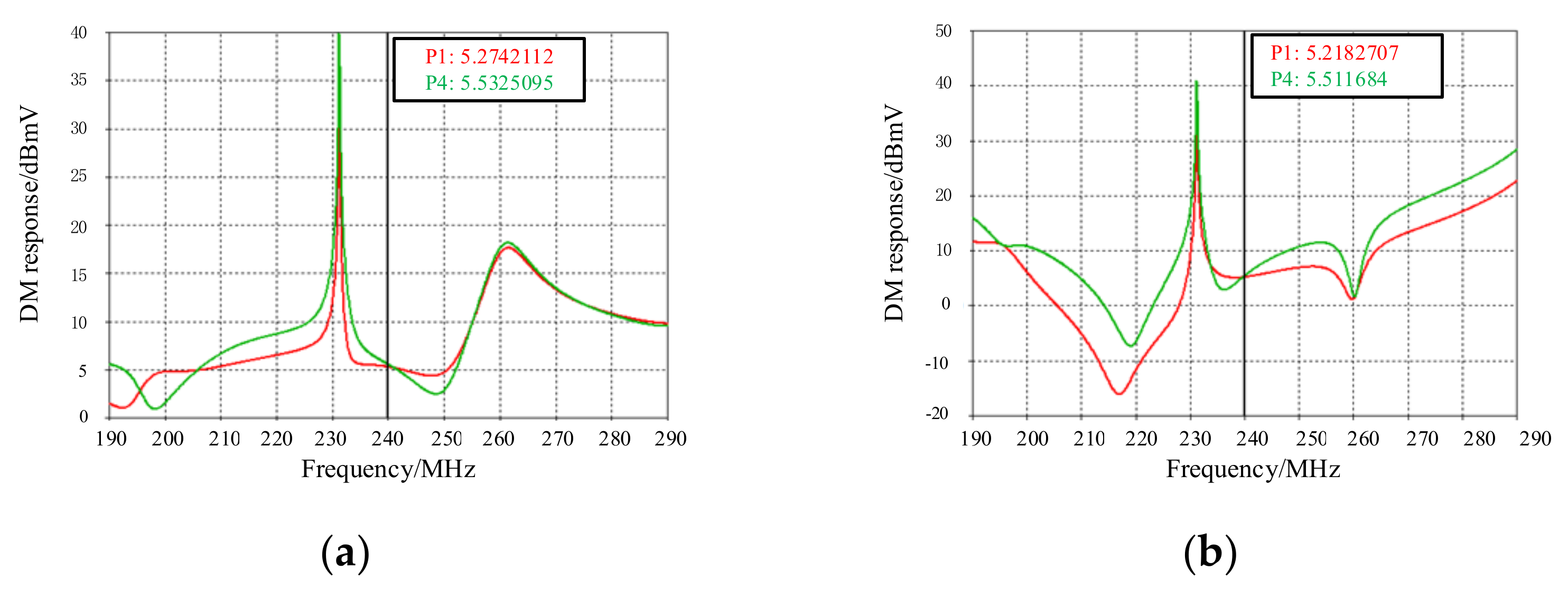
The 240 MHz simulation is taken to describe the details. P1 and P4 represent the response of the right and left end respectively. First, the low-field-intensity simulation is performed. The impedance is 25 Ω at both ends. The responses at the right and left end are 5.53 dBmV and 5.21 dBmV, respectively (In
Figure 7a). Then, the CM excitation sources are adjusted in the injection model. The amplitude at the left is adjusted to 0.52 V. The amplitude at the right is adjusted to 0.521 V, and the phase is −177.9. The responses at the right and left end are 5.51 dBmV and 5.22 dBmV respectively (In
Figure 7b).
Next, the extrapolation simulation is performed. The left end impedance is set to 16.7 Ω, and the right end impedance is 37.5 Ω. This step is to simulate the nonlinear changes that occur in the impedance of the EUT. The plane wave excitation is increased by 12 dB. The responses at the right and left end are 14.06 dBmV and 20.84 dBmV, respectively (In
Figure 8a). Then, the amplitude at the left end is adjusted to 2.08 V, and the right end is adjusted to 2.084 V (their phases are unchanged). The responses at the right and left end are 14.24 dBmV and 20.90 dBmV respectively (In
Figure 8b).
The simulations of 50 MHz, 100 MHz and 340 MHz frequencies are also performed. The simulation results are shown in the
Table 1.
Below 400 MHz, the simulation results show that the method of DBCI can make the responses at both ends consistent with the radiation responses.
When the corresponding relationship is established in the low-field-intensity conditions, the responses in the two conditions are not strictly equal due to the influence of the calculation accuracy of the software. Therefore, there must be an error after the extrapolation. However, the maximum error does not exceed 1 dB after exploration. This means DBCI can be used for HIRF RS test with nonlinear terminations.
5. Test Verification
5.1. Test Configuration
The test is performed in the anechoic chamber. The composition of the test system is shown in
Figure 9: a 2 m-long unshielded two-wire is placed on a horizontal tabletop with the height of 1 m, and both ends are connected to the pass-through load to simulate EUT respectively. The other ends of the two pass-through loads are connected to the spectrum analyzer through the photoelectric conversion module respectively.
During injection, the two current probes are terminated with the signal source. To ensure the same frequency of the two injection sources, a power divider is used to divide a signal into two channels. An adjustable attenuator and a variable phase shifter are connected into the two injection signal paths to realize the adjustment of the injection signal amplitude and phase. A vector network analyser is used to test the phase difference of the two injected signals. During radiation, an antenna is placed as the radiation excitation source at a distance of 1 m from the cable. The other configurations are the same as those in the injection conditions, and the probes are connected to the matching loads.
The key to the test is to ensure that the phase difference of the cable terminal response is consistent with that of the injected excitation source. Only in this way can the effectiveness of the test method be guaranteed.
5.2. Test Process
Combined with the test method in
Section 3, the test is performed as follows:
- (1)
The injection pre-test is performed. The positions of the probes are adjusted to both ends on the cable, and the cable terminal responses are monitored. After the positions are selected, the positions of the current probes at this frequency remains unchanged.
- (2)
The radiation test is performed under low field intensity. The antenna is used to radiate the cable at a specific frequency. The values of the spectrum analyser at both ends are recorded. These values are the response of the left and right cable terminals.
- (3)
The equivalent injection test is performed. The impedance of the left and right terminals remains unchanged. The injected power and phase of the signal source is adjusted to make the responses of the pass-through loads at both ends equal to those in radiation conditions.
- (4)
The high-field-intensity extrapolation test is performed. The pass-through loads at both ends are changed respectively to realize the change of the impedance under high field intensity. The radiated field intensity increased by 10 dB, and the responses of the left and right terminals are recorded.
- (5)
The equivalent injection test is performed under high field intensity. The left and right impedance conditions (step (4)) are unchanged. The amplitude of the two injection sources is increased by 10 dB and the phase difference is unchanged. The responses of the two terminals are recorded.
The nonlinear change of the EUT impedance under HIRF is simulated by changing the impedance value of the pass-through load. The large change in impedance value simulates a more severe situation.
5.3. Test Results and Analysis
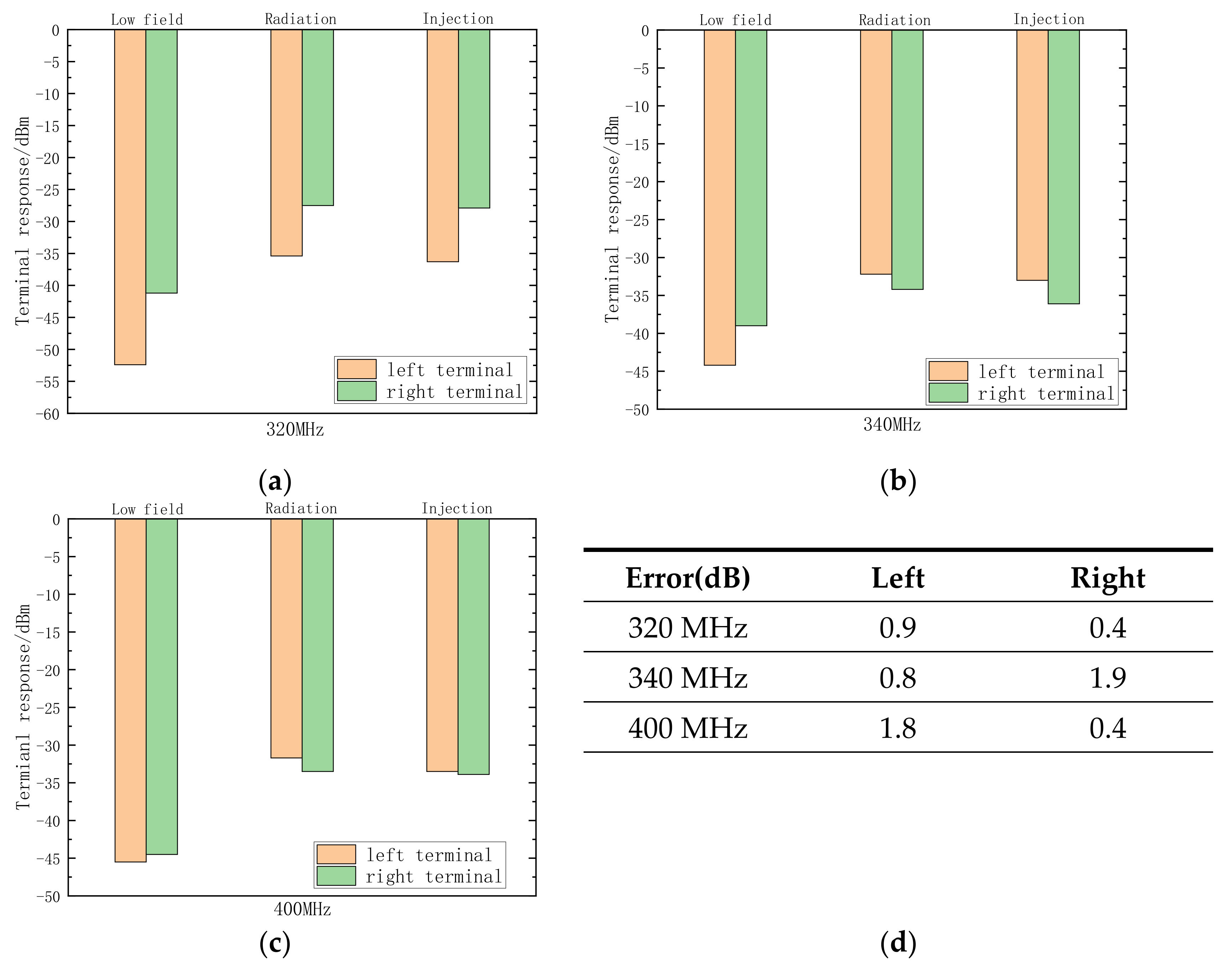
The impedance values of the left and right ends at different frequencies and the corresponding test results are shown in
Figure 10.
From
Figure 10, in the low-field-intensity pre-test, the DBCI instead of radiation is very accurate. On this premise, the responses of both ends during DBCI and radiation are relatively equal after linear extrapolation by 10 dB. When both ends of the pass-through load impedance change nonlinearly under high field intensity, the maximum error is 1.9 dB. In actual radiation conditions, the excitations caused by interference are on the cables. Additionally, the injected interference is concentrated in a certain position of the cable. The cable has the insertion loss, and the difference in the transmission distance of the interference in the two conditions may lead to test errors. Nevertheless, all errors are less than 3 dB, which meets the engineering requirement.
It should be noted that the impedance of the EUT under the low-field-intensity condition is the impedance during normal operation. The nonlinear change in the impedance of the EUT is simulated by transforming the impedance value of the pass-through load under the condition of high field intensity. Therefore, the test method of DBCI substituting high-field-intensity electromagnetic for radiation test is effective for nonlinear terminals.
6. Conclusions
Based on the weak imbalance theory, the theoretical model of the unshielded two-wire circuit systems is established. It is found that the injected excitation voltage source has a linear relationship with the radiated field intensity and has nothing to do with the impedance of the EUT at both ends. Then, it solves the problem that the EUT at both ends are nonlinear terminals. This lays the foundation for linear extrapolation.
The test method of substituting DBCI for the HIRF electromagnetic radiation is proposed towards unshielded two-wire circuit systems. First, the low-field-intensity pre-test is performed to find the linear corresponding relationship between injected excitation and radiated excitation. Then, the high-field-intensity extrapolation test is performed. After linear extrapolation, the responses of the injected excitation to the EUT are equal to those of the radiated excitation.
From the simulation, the results are ideal at frequencies below 400 MHz. The responses of both ends during radiation and injection can be guaranteed to be equal after linear extrapolation. It is proved that the test method can be applied to nonlinear terminals. The pass-through load test is designed for verification. The responses of the EUT at both ends by DBCI are consistent with the responses in radiation conditions. The maximum response error of EUT is 1.9 dB, which meets the engineering requirement. Nevertheless, the process of the method is relatively cumbersome. When the corresponding relationship is established under low field intensity, the amplitude and phase of the two injected excitation sources need to be adjusted, which places higher requirements on the operators. In general, the test method provides another convenient way for the RS test of weapons. Compared to the case that accurately simulating the EUT responses at both ends in a high-field-intensity electromagnetic radiation environment, the method is still considerable even if it costs some workforce and material resources. The unshielded two-wire is a cable that transmits low-frequency signals, and the high-frequency interference signals coupled to this cable have huge losses through transmission. In addition, due to the limitation of the working frequency of the current probe, the working state is relatively stable at frequencies below 400 MHz. Therefore, this method is suitable for sinusoidal HIRF test in the frequency range below 400 MHz.
Reference [
4] studies the method of BCI for high-field-intensity radiation in the two-core shielded wire coupling channel. In the manuscript, the equivalent test method is studied in the unshielded two-wire coupling channel. The test method can avoid the influence of the impedance parameters of the two equipment at both ends, which can apply to the nonlinear terminals for the HIRF RS test. Further, the equipment at both ends of the cable can be tested at the same time in the unshielded two-wire circuit of the weapon systems.
This method is based on the sinusoidal wave high-field-intensity electromagnetic radiation, and the narrow-band electromagnetic pulse (EMP) is a modulated sinusoidal wave, so it is applicable in theory to the narrow-band EMP with a low frequency and a slow rising edge. However, in the operation process, it is difficult to ensure that the injection waveform (frequency and rising edge) of the narrow-band EMP is not distorted, as this will put forward higher requirements for the current probe. In addition, since the narrow-band EMP are not continuous, the two-way signals injected by the two probes will be superimposed at the terminals. Additionally, the time delay problem of the two signals is the focus of the next research.
Author Contributions
Conceptualization, J.S.; methodology, J.S.; X.P. and G.W.; software, J.S. and X.L.; validation, J.S.; X.P. and X.L.; formal analysis, H.W.; investigation, H.W.; resources, G.W.; writing—original draft preparation, J.S.; writing—review and editing, J.S.; X.P. and X.L.; funding acquisition, X.L. All authors have read and agreed to the published version of the manuscript.
Funding
This research was funded by the National Natural Science Foundation of China under Grant 61901521.
Data Availability Statement
Conflicts of Interest
The authors declare no conflict of interest.
References
- MIL-STD-464C: 2010; Electromagnetic Environmental Effects Requirements for Systems. Department of the Air Force: Arlington, VA, USA, 2010.
- Pan, X.; Wei, G.; Lu, X.; Wan, H.; Fan, L. Test method of using differential mode injection as a substitute for high intensity electromagnetic pulse radiation. Chin. J. Radio Sci. 2017, 32, 151–160. [Google Scholar]
- Lu, X.; Wei, G.; Pan, X.; Fan, L.; Wan, H. Study on feasibility of double differential mode current injection method under condition of terminal nonlinearity. High Volt. Eng. 2015, 41, 4213–4219. [Google Scholar]
- Pan, X.; Wei, G.; Lu, X.; Li, X. Theoretical model and implementation technique of using injection as a substitute for radiation. High Volt. Eng. 2012, 38, 2293–2301. [Google Scholar]
- Aiello, O. Hall-Effect current sensors susceptibility to EMI: Experimental study. Electronics 2019, 8, 1310. [Google Scholar] [CrossRef] [Green Version]
- Yang, M.; Sun, Y.; Pan, X.; Wan, H.; Lu, X. Testing technology of using twisted pair cable BCI as substitution for high field continuous wave EM radiation. J. Microw. 2018, 34, 72–77. [Google Scholar]
- Sun, J.; Pan, X.; Lu, X.; Wan, H.; Wei, G. Research on the test method of substituting bulk current injection for electromagnetic radiation in the coupling channel of parallel double lines. AIP Adv. 2021, 11, 055205. [Google Scholar] [CrossRef]
- Sun, J.; Pan, X.; Lu, X.; Wan, H.; Wei, G. Test method of bulk current injection for high field intensity electromagnetic radiated susceptibility into shielded wire. IEEE Trans. Electromagn. Compat. 2022, 64, 275–285. [Google Scholar] [CrossRef]
- Grassi, F.; Spadacini, G.; Marliani, F.; Pignari, S.A. Use of double bulk current injection for susceptibility testing of avionics. IEEE Trans. Electromagn. Compat. 2008, 50, 524–535. [Google Scholar] [CrossRef]
- Marliani, F.; Spadacini, G.; Pignari, S. Double bulk current injection test with amplitude and phase control. In Proceedings of the 18th International Zurich Symposium on Electromagnetic Compatibility, Munich, Germany, 24–28 September 2007; pp. 429–432. [Google Scholar]
- Grassi, F.; Spadacini, G.; Pignari, S. The concept of weak imbalance and its role in the emissions and immunity of differential lines. IEEE Trans. Electromagn. Compat. 2013, 55, 1346–1349. [Google Scholar] [CrossRef]
- Grassi, F.; Pignari, S. Bulk current injection in twisted wire pairs with not perfectly balanced terminations. IEEE Trans. Electromagn. Compat. 2013, 55, 1293–1301. [Google Scholar] [CrossRef]
- Grassi, F. Accurate modeling of ferrite-core effects in probes for Bulk Current Injection. In Proceedings of the IEEE International Conference on Microwaves, Communications, Antennas and Electronics Systems, Tel Aviv, Israel, 9–11 November 2009; pp. 1–6. [Google Scholar]
- Pignari, S.; Canavero, F. Theoretical assessment of bulk current injection versus radiation. IEEE Trans. Electromagn. Compat. 1996, 38, 469–477. [Google Scholar] [CrossRef]
- Grassi, F.; Marliani, F.; Pignari, S. Circuit modelling of injection probes for bulk current injection. IEEE Trans. Electromagn. Compat. 2007, 49, 563–576. [Google Scholar] [CrossRef]
- Grassi, F.; Pignari, S. Immunity to conducted noise of data transmission along DC power lines involving twisted-wire pairs above ground. IEEE Trans. Electromagn. Compat. 2013, 55, 195–207. [Google Scholar] [CrossRef]
- Paul, C. Decoupling the multiconductor transmission line equations. IEEE Trans. Microw. Theory Tech. 2002, 44, 1429–1440. [Google Scholar] [CrossRef]
- Tesche, F.; Miche, V.; Torbjorn, K. EMC Analysis Methods and Computational Models; Beijing University of Posts and Telecommunications Press: Beijing, China, 2009. [Google Scholar]
| Publisher’s Note: MDPI stays neutral with regard to jurisdictional claims in published maps and institutional affiliations. |
© 2022 by the authors. Licensee MDPI, Basel, Switzerland. This article is an open access article distributed under the terms and conditions of the Creative Commons Attribution (CC BY) license (https://creativecommons.org/licenses/by/4.0/).


