Article

Analysis and Design of a Smart Controller for Managing Penetration of Renewable Energy Including Cybersecurity Issues

by
Harshavardhan Palahalli
,
Marziyeh Hemmati
and
Giambattista Gruosso
*
Politecnico di Milano, Dipartimento di Elettronica, Informazione e Bioingegneria, Piazza Leonardo da Vinci, 32-20133 Milan, Italy
*
Author to whom correspondence should be addressed.
Electronics 2022, 11(12), 1861; https://doi.org/10.3390/electronics11121861
Submission received: 13 May 2022 / Revised: 6 June 2022 / Accepted: 8 June 2022 / Published: 13 June 2022

Abstract

:
This article presents an optimal distributed energy resource management system for a smart grid connected to photovoltaics, battery energy storage, and an electric vehicle aggregator. These management systems are one of the key factors for the optimal control of power converters connected to the grid. The proposed management system includes the communication architecture necessary for realizing the information flow between the individual control of the distributed generators and the master supervisory control algorithm. The work carried out on two levels is first to design a control strategy for energy management and validate it with the grid in real-time hardware-in-the-loop simulation integrating the IEC61850 communication layer and physical intelligent electronic devices. The second is to analyze the vulnerabilities of the designed methodology for cybersecurity threats explicitly with the extension of IEC61850 to electric vehicle aggregators for communication with the master energy management. A man-in-the-middle attack conducted in the supervisory communication layer enabled us to investigate the effects of such an attack on the performance and operation of the smart electric grid.

1. Introduction

The decentralization of a power flow is a common trend in the electric network to increase the power penetration of renewable energy resources and tap local the energy sources available in the community [1,2,3]. This decentralization will significantly impact the grid services, especially in managing the power at the transmission level. Hence, to facilitate the decentralization of power flow and increase the number of DERs in the power network, a power management system [4,5,6] is introduced that takes the input from the transmission system based on the unit commitment and participates in the energy market [7]. The power demand is locally met with a high penetration of the PV system, high utilization of BES, and the participation of an EV aggregator. DERMS will take all the burden from the uncertainties [8] occurring in presence of EVs and other renewable energies such as PV systems and give a reliable estimation of the demand requirements to solve the unit commitment problem of the transmission system operator.
The crucial functions performed by DERMS are aggregation, simplification, optimization, and translation [7,9]. The aggregation function identifies the available energy resources, locates the different DERs and plans their penetration to the power network. The services that are provided by the identified DERs to the grid are formalized in the simplification process. The good exploitation of DERs in achieving the proposed grid services is performed in optimization functionality. Whereas the translation enables seamless information flow among all the systems participating in DERMS by adopting a suitable communication protocol, it supports the systems running different protocols and allows interoperability.
DERMS is not just an energy management system but also a facilitator for swift and extremely reliable communication [10] among DERs and TSO. Since DERMS operates with multiple communication protocols [11], it is inclined towards cybersecurity threats [12]. Much research has been conducted in this direction with the integration of EV aggregators to manage power flow. As EV aggregators can be reached by civilians, providing physical security is an issue, and it is more prone to the threats that can occur in mishandling information. The communication protocols that are used in enabling the information flow between the EV and the substation are OCPP, ISO15118, open ADR [13], and IEC61850. A study has proposed a combination of OCPP and IEC61850 in realizing the communication between the EV aggregator and the DSO [14]. The possibility of the successful utilization of IEC61850 in EV mobility was discussed in [15]. Using IEC61850 in DERMS with BES participation is discussed in [16].
IEC61850 is a popular industrial communication protocol [17,18]; its advancement in technology, strict real-time information flow, and inter-operable characteristics [19] lead it to make a quick jump into the electric grid as a substation protocol. This provides the communication interface among all the levels of the substation devices such as the process bus level, bay level, and the supervisory level. The bay level communication is often horizontal among the IEDs using GOOSE messages [20], whereas the other two levels are vertical with sample measured values in the process bus and MMS [21] at the supervisory level. In this work, to enable the communication of DERMS with DERs, the IEC61850 MMS protocol is implemented, and the information model is required to realize the communication explained in the later section. To have a fast transfer of messages, IEC61850 is not encrypted [22], and extending this type of protocol to EV aggregation can compromise all the systems participating in DERMS. Therefore, the use of IEC61850 in DERMS should be investigated before the system is implemented in the power network.
Previous studies such as [23,24,25] limit the analysis to the implementation of the DER energy management system for vehicles using IEC61850 without a deep analysis of the vulnerabilities of in-encrypted protocol on the power system. [26] delivers the synthesized datasets to study cybersecurity attacks in the substation with the detailed implementation of the attack model, however, the attack scenarios and the grid performance are not discussed. The authors in [27] have well demonstrated the IEC61850 GOOSE and MMS attacks, but it is limited to PV inverters.
In the present work, we want to bridge the gap in analyzing the performance of the power system network during a cybersecurity attack and investigate the DERMS control and the power system behavior at critical times.
The DERMS system implementation to control the DERs such as the PV system, BES system and an EV aggregator present in the modified IEEE 13 node test feeder network [28] is realized in a real-time simulated grid with the hardware-in-the-loop [29,30] configuration exchanging the data in real-time through the IEC61850 protocol in a physical Ethernet communication network. Physical IEDs are interfaced with the simulated grid to investigate additional protection scenarios along with the DERMS. The objectives of this work are as follows:
  • To develop an analytical control algorithm used in DERMS to optimally utilize the DERs for the maximum power production of PV and handling an EV aggregator using the BES system based on fuzzy logic.
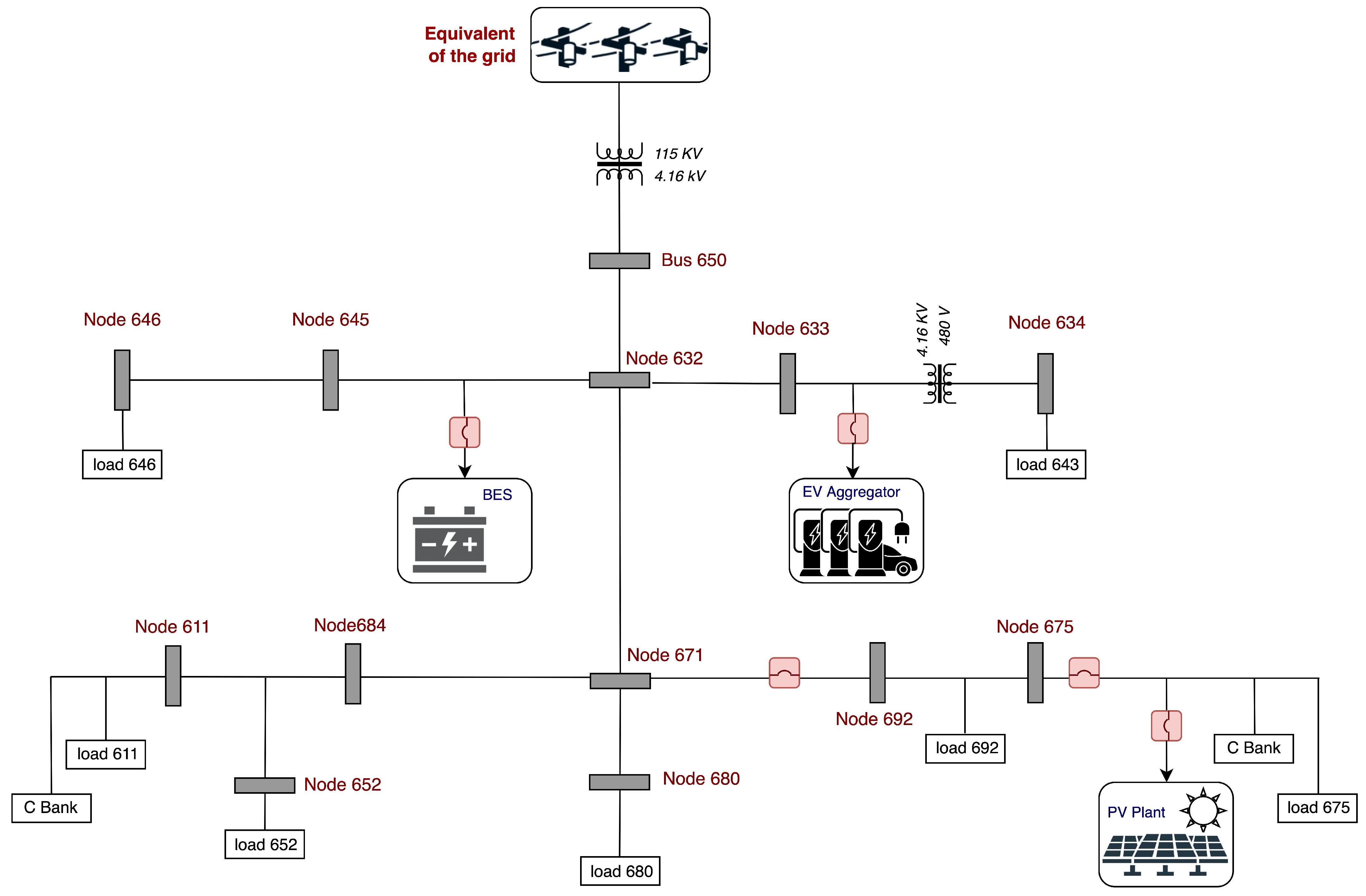
  • To successfully realize DERMS to manage the DERs present in modified IEEE 13 node test feeder network using the IEC61850 communication protocol using the HIL simulation setup.
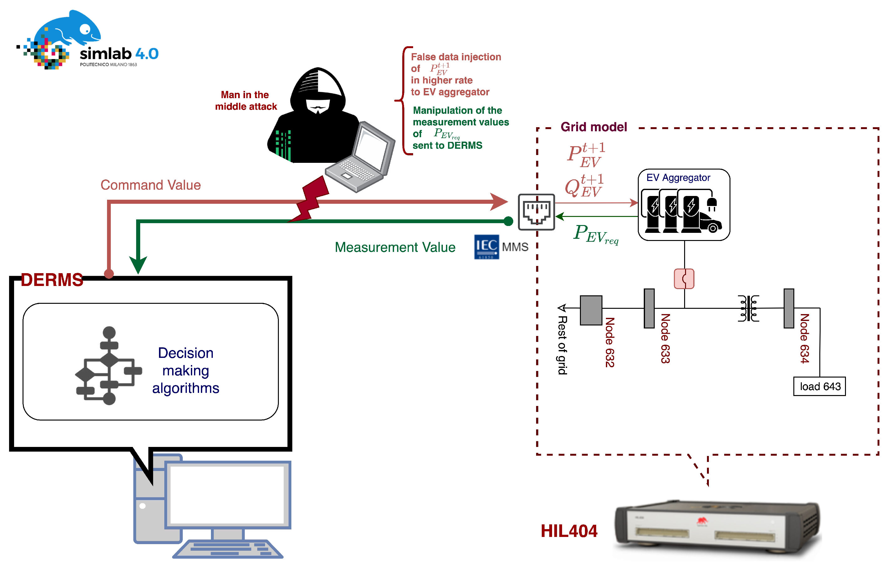
  • To investigate the vulnerability threat scenarios by performing man-in-the-middle attacks exploiting EV aggregation as a vulnerable point.
The organization of the article is as follows. The integration of the DERs into the IEEE 13 node test feeder network is described in Section 2; the DERMS architecture and the control algorithm are explained in Section 3; the HIL simulation setup for the DERMS implementation with the physical communication network and IEDs is evidenced in Section 4; the discussion of the obtained results and validation is provided in Section 5; and finally, the conclusion is drawn in Section 6.

2. Modeling Electric Grid

The investigation of the proposed DERMS was performed on a modified IEEE 13 node test feeder network shown in Figure 1. An additional PV generator, BES system and EV aggregator were added to the original network. The network is a three-phase unbalanced system, operating at 4.16 kV and 50 Hz. A total of 1040 kW of the load is connected at various points in the network. The modeling of PV and BES systems [31] for a real-time target is adopted as described in [32,33] and the respective power rating is in Table 1. In the case of EV, the same model of the BES system was used but the direction of the power flow with the set reference power was modified to be treated as an active load. The DERs will have their control that receives the set reference of power from the master power control of DERMS and operates at a set power level with an injection of power in the specified direction.

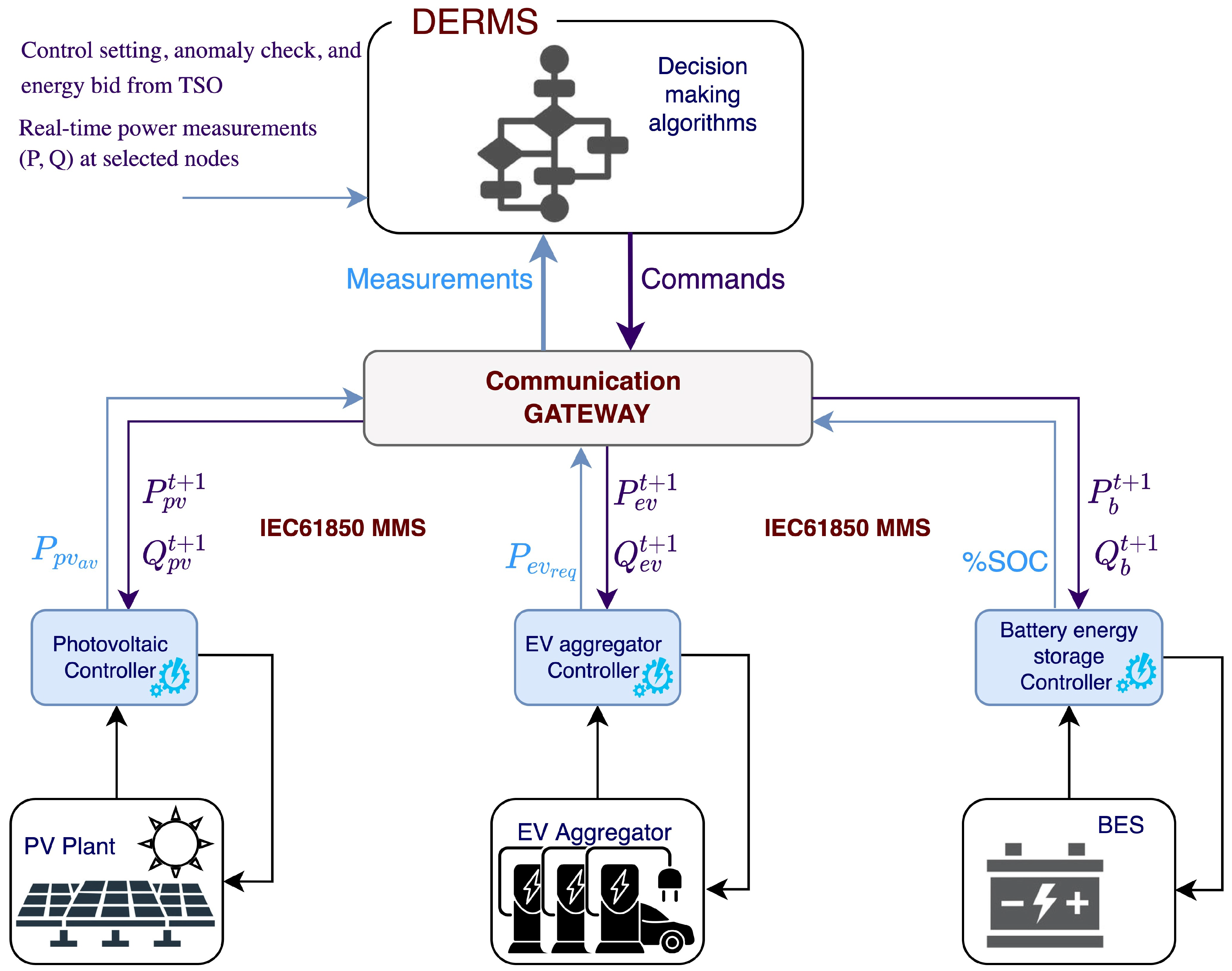
3. Distributed Energy Management System

DERMS is the combination of communication network protocols and the control algorithm. It often operates with multiple communication protocols to enable interoperability among the DERs in which a different communication protocol might have been used. In this work, we implement the DERMS with an IEC61850 MMS communication protocol to transfer information between the local DERs and the master control. This gathers the input required for the decision-making control algorithm and in order to send the reference power for the DERs to operate at optimal power generation. The architecture of the DERMS is given in Figure 2, it receives the power requested from EV, the power available for generation at the PV site, the battery state of charge in percentage, and determines the power references to operate P p v t + 1 , P b a t t + 1 and P e v t + 1 for the PV, BES and EV aggregator, respectively.

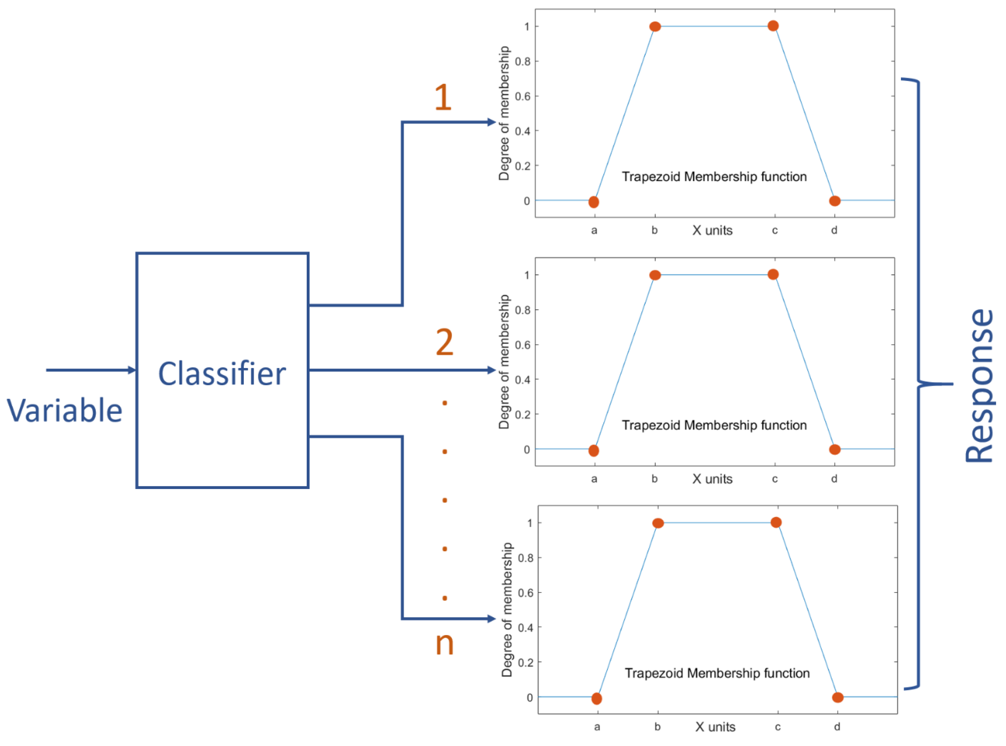
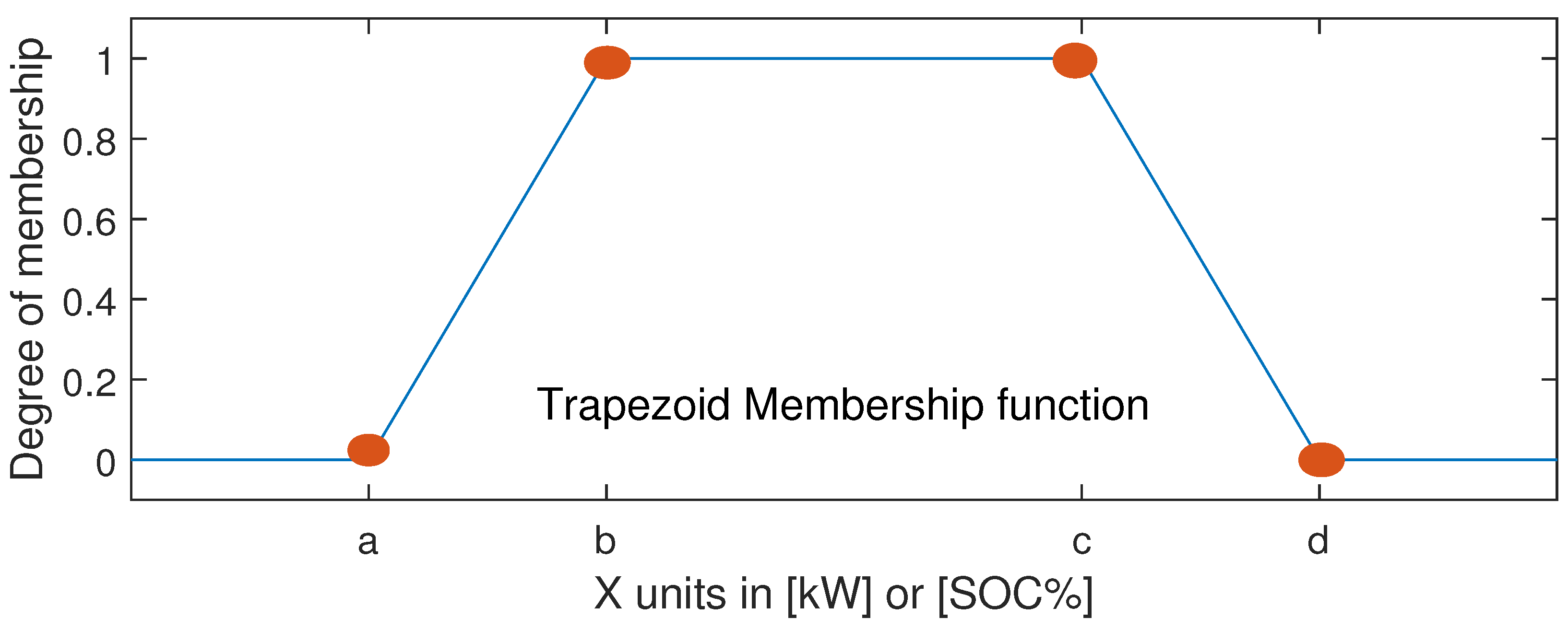
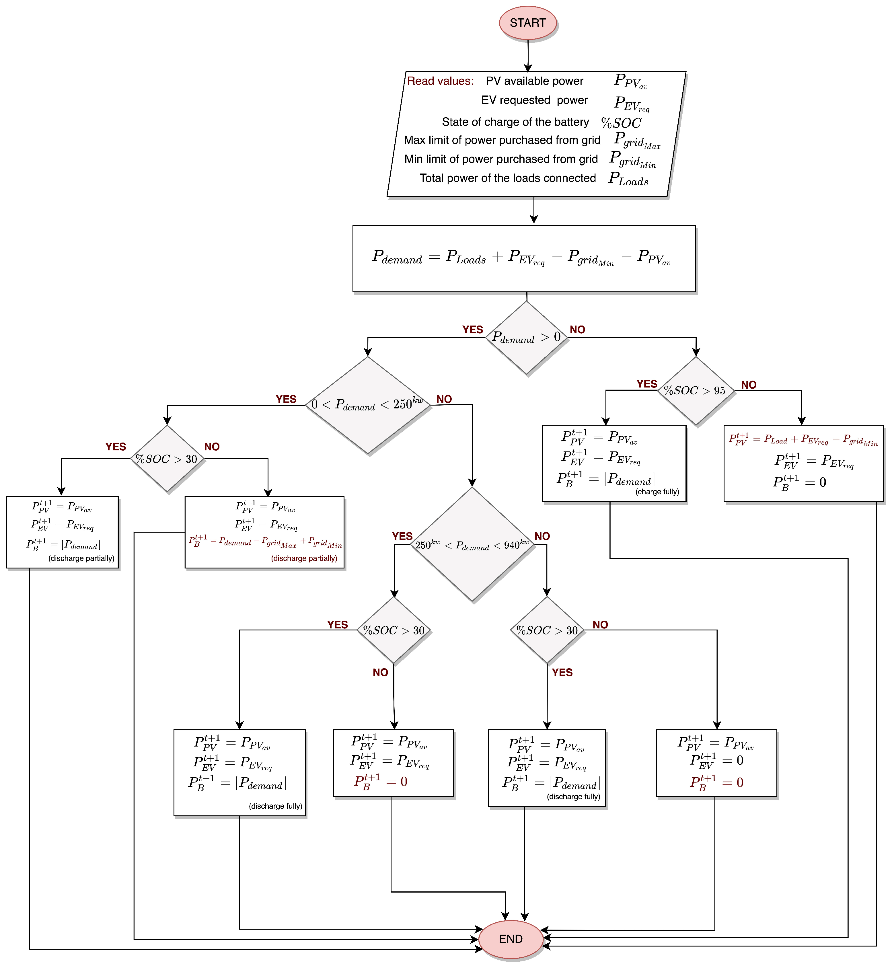
3.1. DERMS Control Algorithm

An analytical energy management system is proposed in this work to manage the power flow that determines the optimal power generation of DERs. It is a master control that determines the reference power for the BES, aggregated EV, and PV system. It also regulates the SOC of BES. In BES, the power flow is bidirectional to charge and discharge the batteries, whereas in the case of the PV and EV aggregator, the power flow is unidirectional only with the generation and consumption, respectively. Once the DERMS issues the reference power, the respective local controllers will ensure the power injection at the set rate from the DER in the specified direction by maintaining a balance between the generation and demand of power. The power balance equation and the constraints of the grid and DERs participating in DERMS are given as follows:
By neglecting the power transmission loss, for any given time ’t’, the power balance in the DERMS is given by Equation (1). We can treat the EV aggregation system as an active load, and hence the power demand is given by Equation (2).
P g r i d ( t ) + P p v ( t ) + P l o a d s ( t ) + P b a t ( t ) + P E V ( t ) = 0
P d e m a n d ( t ) = P l o a d s ( t ) + P e v ( t ) P g r i d ( t ) P p v ( t )
P p v ( t ) P a v a i l a b l e
P b a t m i n P b a t ( t ) P b a t m a x
S O C b a t m i n S O C b a t ( t ) S O C b a t m a x
P e v m i n P e v ( t ) P e v m a x
P g r i d m i n P g r i d ( t ) P g r i d m a x
where
  • P g r i d ( t )  power purchased from the upstream grid;
  • P p v ( t )  PV power generated from the DER;
  • P l o a d s ( t )  total power of the connected loads;
  • P b a t ( t )  battery power;
  • P e v ( t )  electric vehicle power;
  • P d e m a n d ( t )  power that should be regulated.
The resulting P d e m a n d ( t ) is compensated with regulating power P b a t ( t ) by following the designed analytical algorithm. The primary limitation on the operation of DERMS are physical constrains of the systems presented in Equations (3)–(5). The first one is the limitation by the PV system, where the injected power P p v ( t ) depends on the maximum power available over the installed capacity, which is highly dependent on the weather characteristics. The second limitation is set by the active load EV, whose power injection is limited by the number of vehicles available; in other words, an aggregation with a minimum rating of capacity is formed, and in the case of the BES system, a fixed installed capacity with maximum power and minimum power rating is known and very interested in the variable S O C b a t ( t ) . The final one given in Equation (7) is an operating constraint, which is received by the transmission system operator and based on day-ahead scheduling and participating in the energy market. Traditionally, it is always less than the maximum bid amount of power P g r i d m a x , but due to the high penetration of renewable energy systems, a minimum limit to draw the power P g r i d m i n can be imposed.
To design the DERMS control system, the power demand P d e m a n d ( t ) given in Equation (2) was taken as the first input, and the SOC of the battery S O C b a t ( t ) given in Equation (5) and the power demand requested by the EV P r e q u e s t ( t ) are taken as the second and the third input, respectively. The DERMS algorithm determines the reference P b a t ( t ) and P e v ( t ) given in Equation (6) as outputs/Finally, for the PV system, the reference P p v r e f ( t ) is analytically calculated using Equation (1) while respecting Equation (3).
In order to avoid very drastic decision making, the system relies on fuzzy logic to weight and average the system inputs and thus allow smoother operation.
The membership function of the inputs is determined according to the physical and operational constraints of DERs [34]. For each variable, a classifier is applied in order to select the range of evaluation. The logic of this classifier is very simple: evaluate the interval of the signal and select the proper membership function—as shown in Figure 3. Inside the interval, the decision is made by means of a trapezoidal rule defined by the main parameters a,b,c,d (according to Figure 4 and reported in Table 2. The first input P d e m a n d ( t ) is associated with four membership functions, which is interesting since the negative power demand shows that the sum of PV available and the grid minimum power are more than the required load and EV demand. The available excess power is used for charging the BES system. The positive load demand is further classified into low, medium and high membership functions, and their respective parameters for forming trapezoidal membership functions of all the inputs and outputs are given in Table 2, which can be mapped to the generic trapezoidal membership functions given in Figure 4.
The control algorithm of DERMS at any time instant ’t’ for optimal power flow is given in Figure 5 and based on the set rules, it generates the output power reference for the EV aggregator and the BES system. For an EV aggregator, most often the set reference output follows the input EV power requested unless the P d e m a n d ( t ) is very high and the PV power production is lower than 10 % of the installed capacity. The control output has five output modes such as c h a r g e f u l l y , c h a r g e p a r t i a l l y , d i s c h a r g e f u l l y , d i s c h a r g e p a r t i a l l y and I d l e .

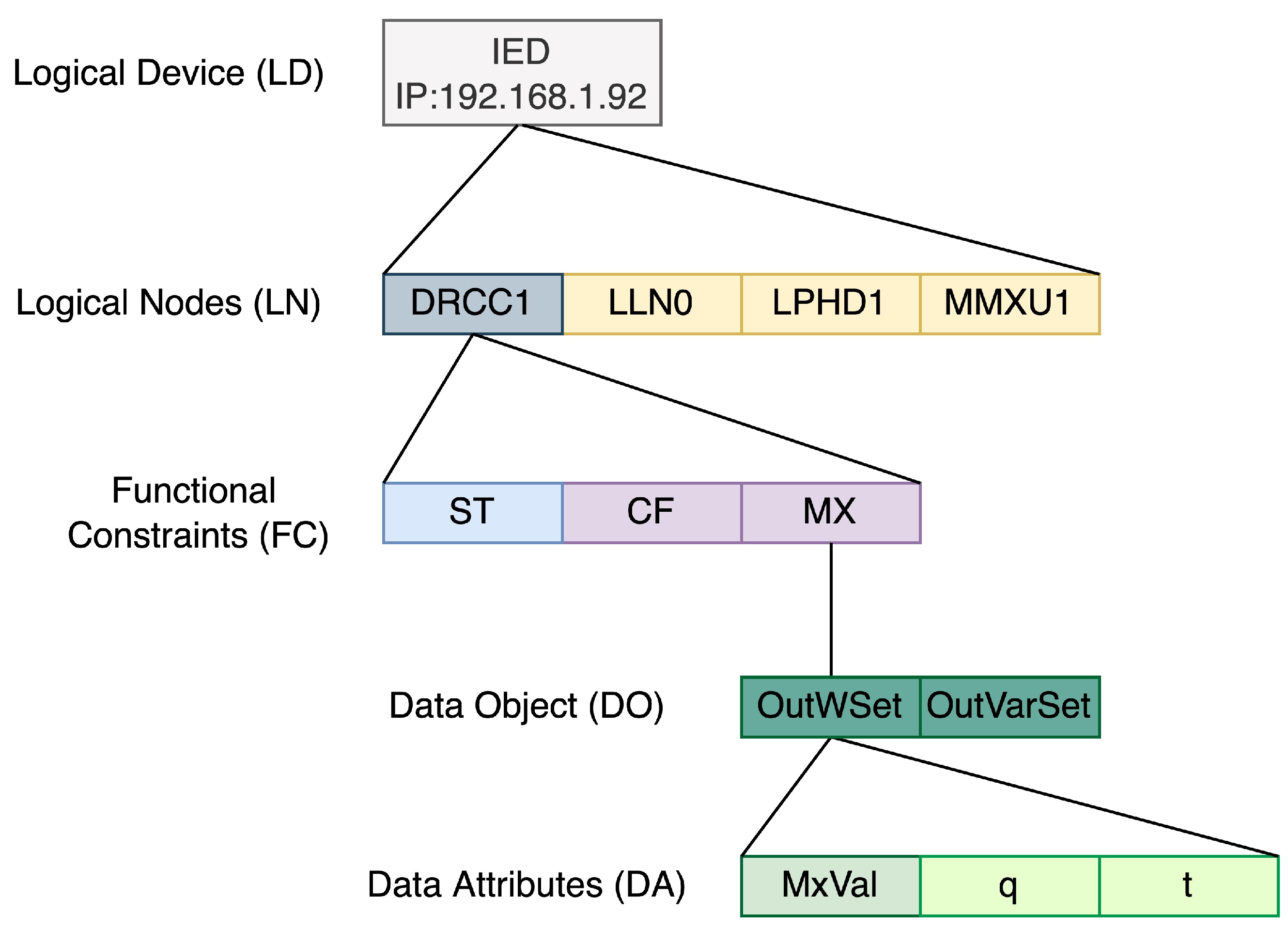
3.2. Information Model of DERs Used in Proposed DERMS

To set up the communication interface, the client and server model is necessary. The master DERMS control is a client and the DERs local controllers are the servers; these DER servers need to send the messages with the vital data of the system with the information model complaint to the IEC61850. The information model is vertical where the DER is represented as an IED, a logical device is defined that contains the logical nodes and data objects, and the transferred vital parameters are in the data attributes which are present in the DO. All these data are built in the SCL description language, and each DER model will carry each description file containing an information model of respective DERs along with their IP addresses.
An IEC61850 information model of the PV system is given in Figure 6 and a virtual IED which represents a PV logical device is created within a physical device having an IP address. This PV LD contains many logical nodes such as a DER control action DRCC1 as well as all the control parameters that are exchanged between the DERMS and the local PV controller. Logical node LLN0 has all the associated logical information such as the status of the switch to open and close the DER connection with the point of common coupling. The last logical node MMXU1 carries all the measurement parameters such as the active and reactive power produced, the frequency, voltages currents and their respective angles. Most importantly, the DRCC1 logical node will have configuration CF, control function MX and the status information ST. The data from the external client are sent through the control function MX that carries the active power reference o u t W s e t data attribute. In the case of the BES and EV aggregator system, a similar information model is used but with an additional logical node ZBAT, this logical node carries the information associated with the state of charge and the battery health.

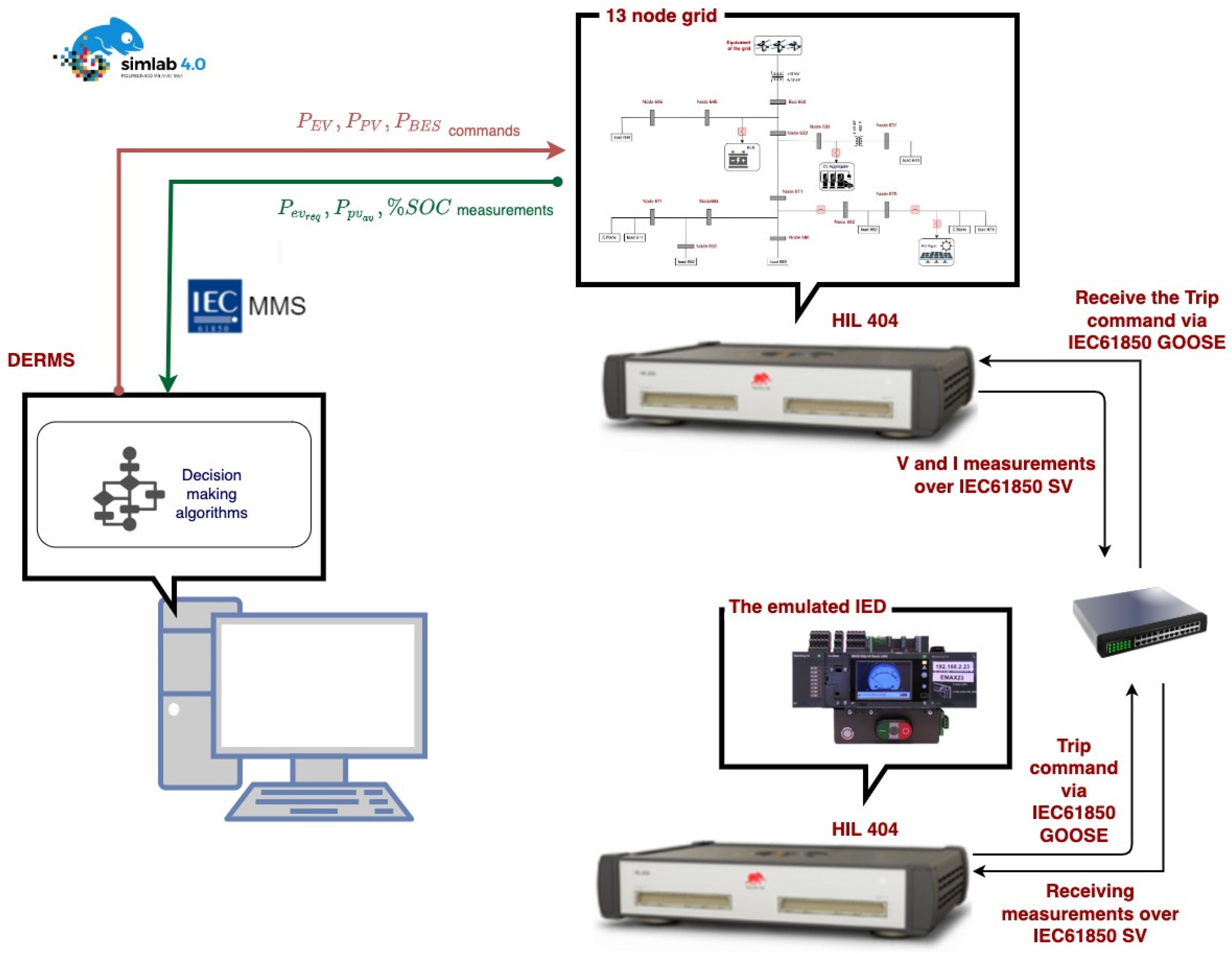
4. Real-Time HIL Simulation Setup and Attack Scenarios

The electric grid with the DERs is run in real-time using the real-time digital simulator Typhoon HIL. The DERMS logic will be in the IEC61850 MMS client present in an external PC that both systems are connected with the physical Ethernet communication via a network switch. As explained earlier and shown in Figure 2, they will exchange the vital parameters and the set references using IEC61850 MMS messages and the complete test-bench setup is shown in Figure 7.
As we are in the initial phase, the protection scenarios are implemented outside DERMS so that we can completely understand the grid behavior with the designed control algorithm. As we investigate further, the identified vulnerabilities are mitigated by providing immunity to DERMS by designing the protection logic alongside the control algorithm, making DERMS smart and reliable. External IEDs are used to investigate the grid protection scenarios. The grid measurements are sent from the real-time simulator to the IED using IEC61850 SV messages, and then if the IED trips, the relevant information is given to the mapped circuit breaker in the grid to break the circuit. This flow of data from the IED to the circuit breaker is sent via IEC61850 GOOSE messages, thereby enabling the complete IEC61850 information model implemented in the test bench. Once the performance of the grid with the DERMS is verified in the normal operation, “if-Then” scenarios are applied by pushing the limits of the grid and DER parameters. Later, man-in-the-middle attack scenarios are analyzed by breaching the security of the network in attack mode.
In this work, one of the protection scenarios implemented in the IED is reverse power flow. When the power flow changes direction, the IED trips and sends the open command to the circuit breaker mapped to the IED. This type of protection is implemented here as an example to construct a scenario. The advantage is that placing an IED with reverse power flow protection between the substation connected to the transmission system and the rest of the grid avoids the injection of power from the DERs to the transmission line. As we set the minimum consumption of power from the transmission system, using this kind of protection scenario is valid and it is a good example to demonstrate.

5. Results and Discussion

In this section, various scenarios of the operation of the grid with DERMS while extracting maximum available power from PV and balancing the power of EV and load demand using BES are verified. Later, the implementation and results of the man-in-the-middle passive and active attacks are discussed.

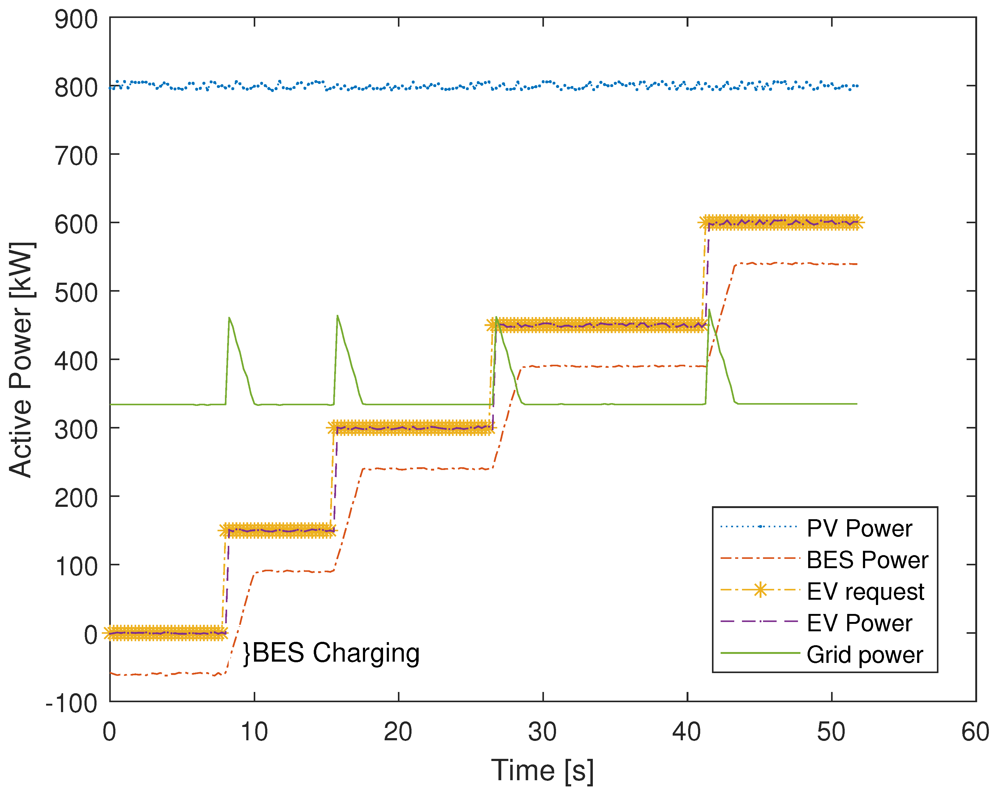
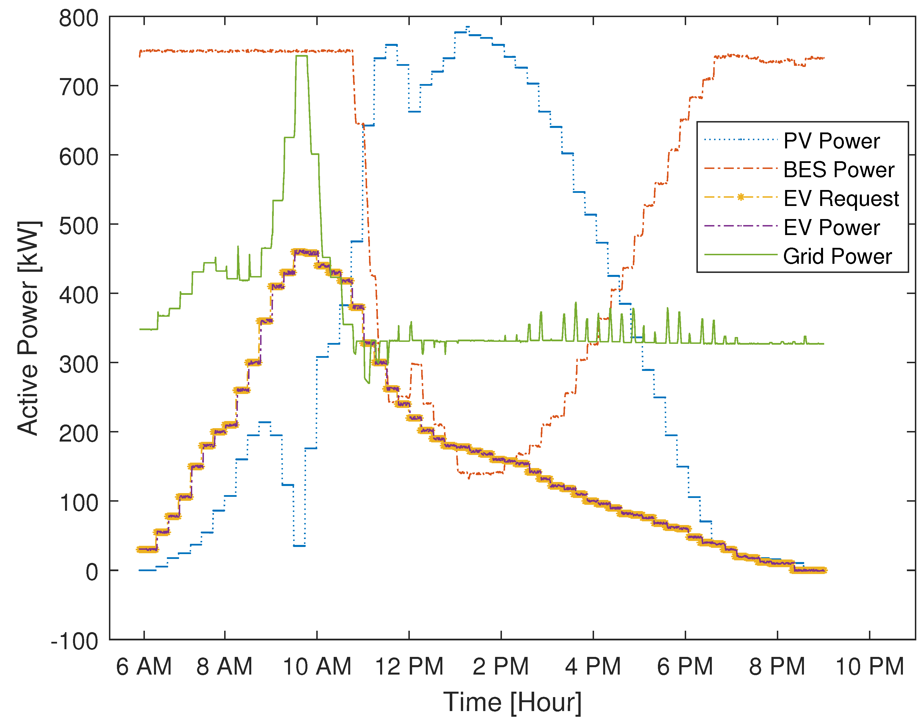
5.1. DERMS Operation Validation

The ability of DERMS to regulate the power of DERs as per the designed control algorithm shown in Figure 5 is tested. The first case to investigate is when the S O C % of the battery is at 70 % , the installed load capacity P l o a d is maintained constant with 1040 kW, the minimum P g r i d m i n and maximum P g r i d m a x power that can be tapped from the grid are 300 kW and 700 kW, respectively, and the PV power available P a v a i l a b l e to extract is set at its maximum installed capacity of 800 kW. The EV demand request is increased from 0 kW to a maximum installed capacity of 600 kW. The obtained results are shown in Figure 8.
In this case, initially, with no EV demand request, the P d e m a n d assigned to the DERMS is −60 kW. As designed, DERMS will extract the maximum available power from the PV system, which is 800 kW, and it will put the BES system in partial charging mode with 60 kW of power. As the EV request power increases, the BES goes from charging to discharging mode. We observed that, in the designed DER system, the response time of the BES system is slower compared to the EV. For the additional support, the grid provides the required power which can be seen as spikes in the grid power in Figure 8.
In the second case, the SOC% of the BES system is maintained at 70%, the PV power P a v a i l a b l e is varied following a daily curve [35], and the EV demand is varied for a daily profile as mentioned in [36] to capture a time-varying sporadic EV request in a day. Figure 9 shows the DERMS performance to manage the power demand of the EV while extracting the maximum available power from PV and keeping the power obtained from the TSO to the minimum possible at all times. While analyzing this case, a fault scenario is studied, wherein the IED present between the EV aggregator and the PCC of the grid interrupts the supply in case of a line–line fault seen in the EV aggregator system. The current and voltage measurement is sent to the external IED that controls the status of the circuit breaker present in the grid via GOOSE messages. Figure 10 shows that the trip command is given by the IED GOOSE to interrupt the circuit at time t = 0 , the fault is cleared within 12.8 ms, re-closure is attempted at t = 2.106 s, and the system is brought to normal operation.
The third case is repeated with the same parameters as in the case 1, but instead of varying the EV demand request, the PV available power is varied from 0 kW to the maximum installed capacity of 800 kW—while keeping the EV power request to 300 kW all the time. Since the P a v a i l a b l e is varied, the P d e m a n d input of the DERMS is varied. The DERMS managed to allocate the requested demand to the EV despite all the changes in the PV power. As the SOC lies at a medium level, the DERMS used its flexibility to fully utilize BES to serve the requested demand by keeping the power consumed by the grid below the set maximum of P g r i d m a x = 700 kW. As the PV available power increases, power consumption from the grid is reduced to the minimum grid consumption of P g r i d m i n = 300 kW first, and then the BES power is reduced, as detailed changes in power levels are given in Figure 11.
The fourth case is executed with SOC in the lower range > 20 % , and as the SOC is very low, the BES operation will depend on the P d e m a n d classification. When the P d e m a n d is not low, BES will maintain the idle state and not participate in power generation, however, when the P d e m a n d is low, it is positive, and the BES will move from an idle state to a partially charging state with the power reference of P B E S = P d e m a n d + P g r i d m i n P g r i d m a x . As the BES is in critical condition, power is extracted from the grid below the maximum level set. It is shown in Figure 12 when the initial EV request is set at 300 kW, the PV is producing approximately 760 kW, with the constant load of 1040 kW, and the resulting P d e m a n d is obtained as 280 kW classified under a medium level; in this condition, the BES is maintained in its idle state. At time t = 12.5 s, the EV request is reduced to 150 kW, making the P d e m a n d shift from medium to low classification with the value of 130 kW in this condition, the DERMS will move BES from an idle state to a partially charging state with the set power reference of −270 kW.

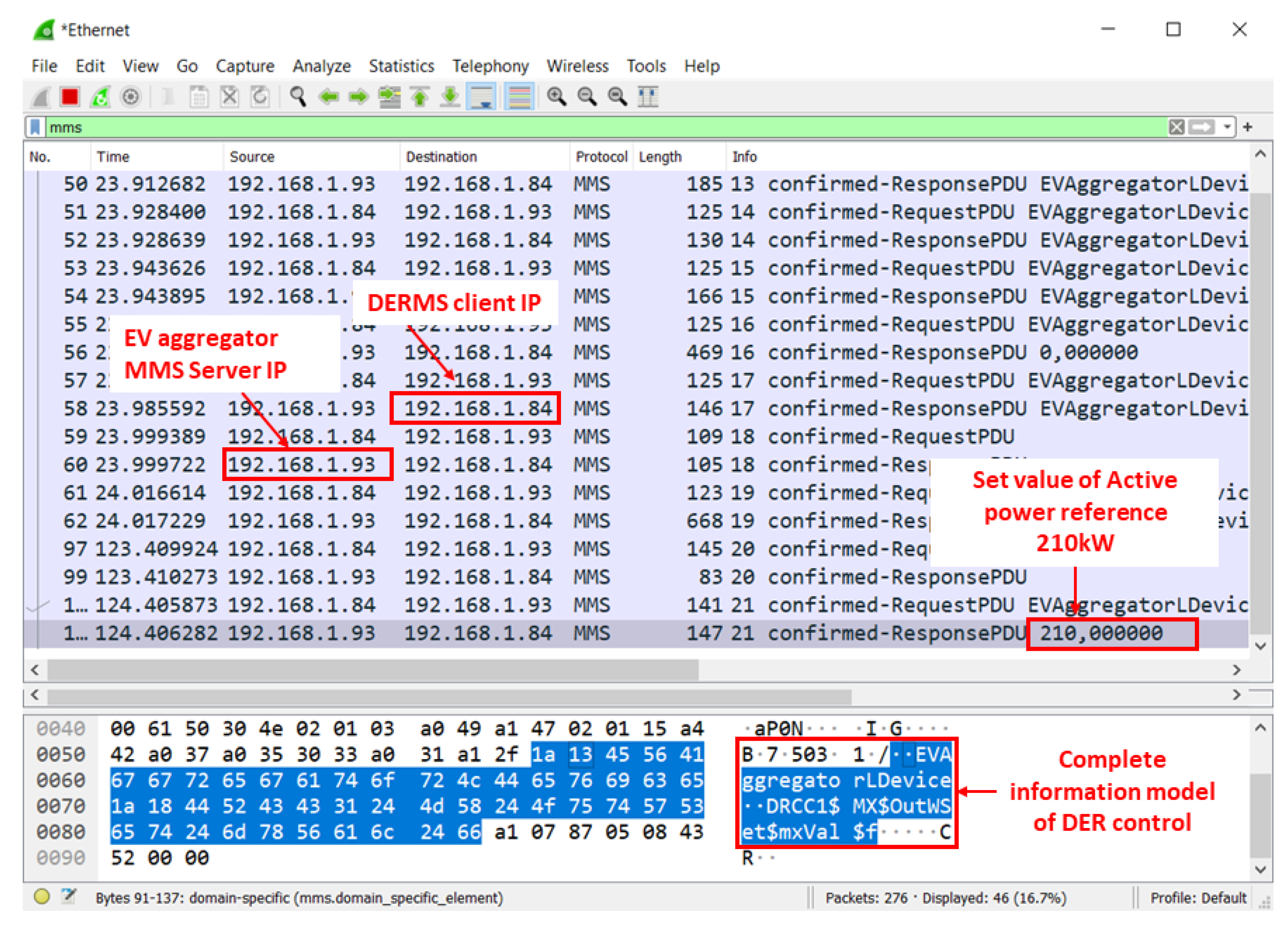
5.2. Man-in-the-Middle Attack Snooping

The attack on the communication network is from the EV side, and as shown in the attack outline given in Figure 13, the DERMS algorithm for such an attack and the grid behavior are tested, with which the contingencies are planned accordingly. As the test bench is correctly validated, now the attack scenario planning is up to the creativity of the test designer. Each scenario might result in different grid behavior: some might not affect the power network, but some attacks can be fatal to the grid.
Snooping is a passive attack in which the attacker gathers all the information regarding the information model and the transmitted data by sniffing the network with software tools. This kind of attack will not cause any problem to the system but it facilitates the attacker with all the required information to plan a catastrophic scenario and disrupt the system. The snapshot of the network sniffing tool is given in Figure 14, and with this tool, we obtained all the necessary information being transferred in the network between the EV aggregator server and the DERMS client running in the IP address of 192.168.1.93 and 192.168.1.84, respectively. The logical nodes and the data attributes are also identified. The sniffed data are analyzed and used to create the active attack.

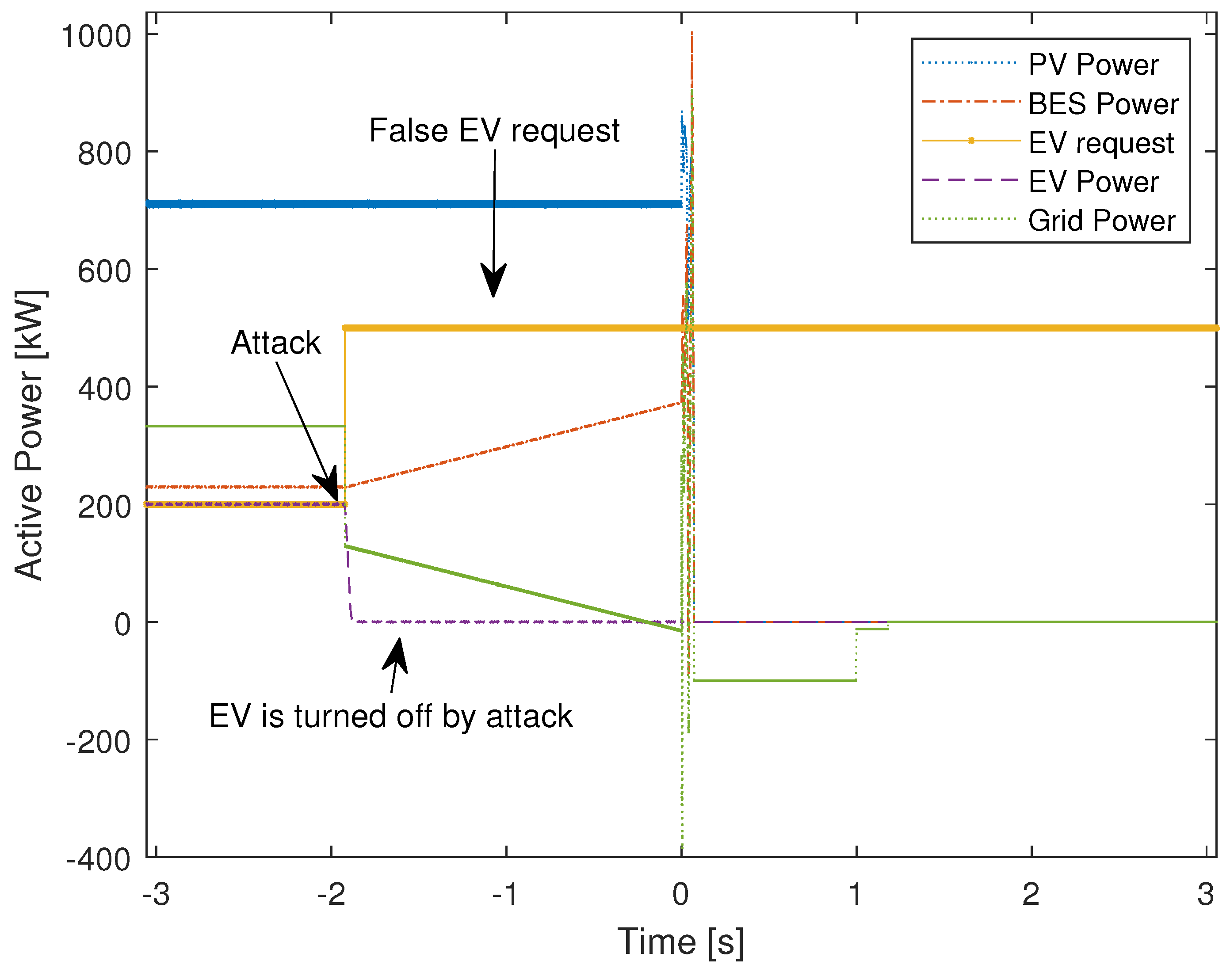
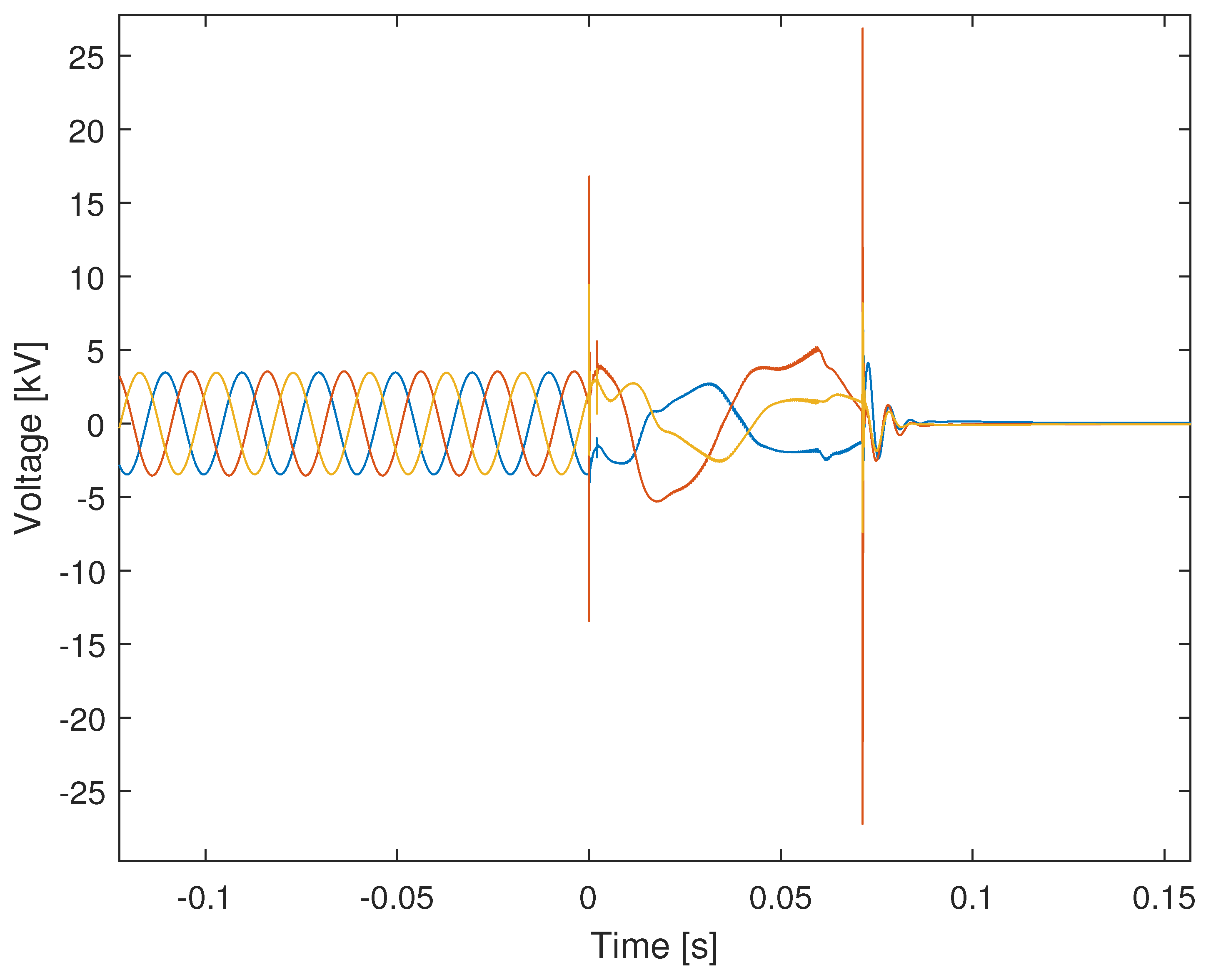
5.3. Man-in-the-Middle Attack: False Data Injection

False data injection is an active attack on the network which can disrupt the functionality of DERMS and have a physical impact on the electrical system. In this attack mode, the EV aggregator MMS server is imitated by another device and made to inject the data into the network with the same information model obtained from the snooped data, thereby attacking the DERMS control algorithm. The false data injection is made at a higher rate to block the original server, pushing DERMS to actuate on the injected data.
The initial conditions of the grid before the attack scenario are as follows: the BES system is operated with 230 kW; S O C % = 70 % ; the PV system is operated with 710 kW; and EV aggregator request is of 200 kW. At this operating condition, the PV system is set to maximum, and the EV demand is served by the BES system. As soon as our attack model hijacks the grid at the time instant of −0.192 s by injecting a false EV request of 500 kW and giving a false active reference of 0 kW for consumption at higher rate, the DERMS will not be able to recognize the disconnection of the EV from the grid and hence it will keep the BES system in discharge mode with an increase in power injection, as shown in Figure 15. It will create a power unbalance and hence the power is injected from the lower end of the grid to the transmission line. An additional power injection is detected by the IED and activates the installed reverse power flow protection to stop this power injection. The IED of the circuit breaker CB1 issues the GOOSE command to break the circuit and CB1 interrupts at time 0 s, and the voltage as seen by CB1 is given in Figure 16.

5.4. Solution for the Caused Cybersecurity Attacks

The immediate solution to these types of attacks is to train the DERMS by implementing protection scenarios inside them and making them smart with additional measurements. The second way is to determine the rate at which the server is publishing the message and any anomaly or change detected is denied with service and warning alarms are issued. Last but not the least, special software can be used to detect the newly present mac address in the network and the denial of services to such new systems can also stop these attacks.

6. Conclusions

In this article, we presented a detailed implementation of DERMS with an analytical control algorithm and communicating using IEC61850 with all the DERs and EV aggregators participating in DERMS. The designed algorithm is tested for all possible cases. Once the stable operation is confirmed, the developed testbed is used to analyze the cybersecurity threat of using the IEC61850 communication protocol in DERMS. As EV aggregators are easily accessible, attacking them to disrupt the system operation is easier. Man-in-the-middle attacks are conducted to analyze the behavior of the designed algorithm under such attacks, and its impact on the grid is studied. This test bench is not limited to the study cases presented here; it can be further extended to study multiple scenarios according to their testing needs, involving DERMS and cybersecurity threats. The future development of this methodology could be summarized as follows:
  • Implement a DERMS based on reinforcement learning and evaluate the behavior of this type of algorithm when data are altered due to cyber-attack and how they can become robust;
  • Compare the reinforcement learning algorithms based on fuzzy logic;
  • Detect the attacks with robust algorithms.

Author Contributions

Conceptualization, H.P., M.H. and G.G.; methodology, H.P. and G.G.; software, H.P. and M.H.; validation, H.P., M.H. and G.G.; investigation, H.P., M.H. and G.G.; writing—original draft preparation, H.P., M.H. and G.G.; writing—review and editing, H.P., M.H. and G.G.; supervision, G.G. All authors have read and agreed to the published version of the manuscript.

Funding

This research received no external funding.

Conflicts of Interest

The authors declare no conflict of interest.

Abbreviations

The following abbreviations are used in this manuscript:
BESBattery energy storage
CBCircuit breaker
DERDistributed energy resource
DERMSDistributed energy resource management system
DSODistribution system operator
EMSEnergy management system
EVElectric vehicle
GOOSEGeneric object oriented substation event
HILHardware in the loop
IEDIntelligent electronics device
LDLogical device
LNLogical node
DAData attribute
DOData object
MMSManufacturing message service
OCPPOpen charge point protocol
PCCPoint of common coupling
PVPhotovoltaic
SCLStructured control language
SOCState of charge
TSOTransmission system operator

References

  1. Blaabjerg, F.; Yang, Y.; Yang, D.; Wang, X. Distributed power-generation systems and protection. Proc. IEEE 2017, 105, 1311–1331. [Google Scholar] [CrossRef] [Green Version]
  2. Yadav, A.; Srivastava, L. Optimal placement of distributed generation: An overview and key issues. In Proceedings of the 2014 International Conference on Power Signals Control and Computations (EPSCICON), Thrissur, India, 8–10 January 2014; pp. 1–6. [Google Scholar]
  3. Islam, M.R.; Lu, H.; Hossain, M.; Li, L. Mitigating unbalance using distributed network reconfiguration techniques in distributed power generation grids with services for electric vehicles: A review. J. Clean. Prod. 2019, 239, 117932. [Google Scholar] [CrossRef]
  4. Strezoski, L.; Stefani, I. Utility DERMS for Active Management of Emerging Distribution Grids with High Penetration of Renewable DERs. Electronics 2021, 10, 2027. [Google Scholar] [CrossRef]
  5. Riffonneau, Y.; Bacha, S.; Barruel, F.; Ploix, S. Optimal power flow management for grid connected PV systems with batteries. IEEE Trans. Sustain. Energy 2011, 2, 309–320. [Google Scholar] [CrossRef]
  6. Jafarian, M.; Soroudi, A.; Keane, A. Distribution System Topology Identification for DER Management Systems Using Deep Neural Networks. In Proceedings of the 2020 IEEE Power and Energy Society General Meeting (PESGM), Orlando, FL, USA, 6 August 2020; pp. 1–5. [Google Scholar] [CrossRef]
  7. Strezoski, L.; Padullaparti, H.; Ding, F.; Baggu, M. Integration of Utility Distributed Energy Resource Management System and Aggregators for Evolving Distribution System Operators. J. Mod. Power Syst. Clean Energy 2022, 10, 277–285. [Google Scholar] [CrossRef]
  8. Rahman, I.; Selak, N.; Paaso, E. Distributed Energy Resource Management System (DERMS) solution for feeder Voltage Management for Utility integrated DERs. In Proceedings of the 2021 IEEE Power & Energy Society Innovative Smart Grid Technologies Conference (ISGT), Washington DC, USA, 21–25 June 2021; pp. 1–5. [Google Scholar]
  9. Albertini, A.D.R.; Yabe, V.T.; Di Santoz, S.G.; Juniorx, G.M. An Overview of Distributed Energy Resources Management System Guidelines and Functional Coverage. In Proceedings of the 2022 IEEE International Conference on Power Electronics, Smart Grid, and Renewable Energy (PESGRE), Trivandrum, India, 2–5 January 2022; pp. 1–6. [Google Scholar]
  10. Nowak, S.; Tehrani, N.; Metcalfe, M.S.; Eberle, W.; Wang, L. Cloud-based DERMS test platform using real-time power system simulation. In Proceedings of the 2018 IEEE Power & Energy Society General Meeting (PESGM), Portland, OR, USA, 5–10 August 2018; pp. 1–5. [Google Scholar]
  11. Ilic, M.D.; Jaddivada, R.; Korpas, M. Interactive protocols for distributed energy resource management systems (DERMS). IET Gener. Transm. Distrib. 2020, 14, 2065–2081. [Google Scholar] [CrossRef]
  12. Onunkwo, I.; Wright, B.; Cordeiro, P.; Jacobs, N.; Lai, C.; Johnson, J.; Hutchins, T.; Stout, W.; Chavez, A.; Richardson, B.T.; et al. Cybersecurity Assessments on Emulated DER Communication Networks; SAND2019-2406; Sandia National Laboratories: Albuquerque, NM, USA, 2019. [CrossRef]
  13. Neaimeh, M.; Andersen, P.B. Mind the gap-open communication protocols for vehicle grid integration. Energy Inform. 2020, 3, 1–17. [Google Scholar] [CrossRef] [Green Version]
  14. Schmutzler, J.; Andersen, C.A.; Wietfeld, C. Evaluation of OCPP and IEC 61850 for smart charging electric vehicles. World Electr. Veh. J. 2013, 6, 863–874. [Google Scholar] [CrossRef] [Green Version]
  15. Huang, R.; Wang, Y.; Shi, W.; Yao, D.; Hu, B.; Chu, C.C.; Gadh, R. Integration of IEC 61850 into a Vehicle-to-Grid system with networked electric vehicles. In Proceedings of the 2015 IEEE Power & Energy Society Innovative Smart Grid Technologies Conference (ISGT), Bangkok, Thailand, 3–6 November 2015; pp. 1–5. [Google Scholar]
  16. Hänsch, K.; Naumann, A.; Wenge, C.; Wolf, M. Communication for battery energy storage systems compliant with IEC 61850. Int. J. Electr. Power Energy Syst. 2018, 103, 577–586. [Google Scholar] [CrossRef]
  17. Palahalli, H.; Ragaini, E.; Gruosso, G. Smart Grid Simulation Including Communication Network: A Hardware in the Loop Approach. IEEE Access 2019, 7, 90171–90179. [Google Scholar] [CrossRef]
  18. Mackiewicz, R. Technical overview and benefits of the IEC 61850 standard for substation automation. In Proceedings of the 2006 Power Systems Conference and Exposition, Atlanta, GA, USA, 29 October–1 November 2006; pp. 623–630. [Google Scholar]
  19. Hemmati, M.; Palahalli, H.; Gruosso, G.; Grillo, S. Interoperability analysis of IEC61850 protocol using an emulated IED in a HIL microgrid testbed. In Proceedings of the 2021 IEEE International Conference on Communications, Control, and Computing Technologies for Smart Grids (SmartGridComm), Aachen, Germany, 25–28 October 2021; pp. 152–157. [Google Scholar]
  20. Palahalli, H.; Hemmati, M.; Ragaini, E.; Gruosso, G. Hardware In The Loop Simulation of the Smart Grid with the inclusion of IEC61850 Communication Protocol. In Proceedings of the IECON 2021—47th Annual Conference of the IEEE Industrial Electronics Society, Online, 3–16 October 2021; pp. 1–6. [Google Scholar]
  21. Burbano, R.A.G.; Gutierrez, M.L.O.; Restrepo, J.A.; Guerrero, F.G. IED design for a small-scale microgrid using IEC 61850. IEEE Trans. Ind. Appl. 2019, 55, 7113–7121. [Google Scholar] [CrossRef]
  22. Rajkumar, V.S.; Tealane, M.; Ştefanov, A.; Palensky, P. Cyber attacks on protective relays in digital substations and impact analysis. In Proceedings of the 2020 8th Workshop on Modeling and Simulation of Cyber-Physical Energy Systems, Sydney, Australia, 21 April 2020; pp. 1–6. [Google Scholar]
  23. Schmutzler, J.; Wietfeld, C.; Andersen, C.A. Distributed energy resource management for electric vehicles using IEC 61850 and ISO/IEC 15118. In Proceedings of the 2012 IEEE Vehicle Power and Propulsion Conference, Seoul, Korea, 9–12 October 2012; pp. 1457–1462. [Google Scholar]
  24. Ali, I.; Hussain, S.S. Communication design for energy management automation in microgrid. IEEE Trans. Smart Grid 2016, 9, 2055–2064. [Google Scholar] [CrossRef]
  25. Nadeem, F.; Aftab, M.A.; Hussain, S.; Ali, I.; Tiwari, P.K.; Goswami, A.K.; Ustun, T.S. Virtual power plant management in smart grids with XMPP based IEC 61850 communication. Energies 2019, 12, 2398. [Google Scholar] [CrossRef] [Green Version]
  26. Biswas, P.P.; Tan, H.C.; Zhu, Q.; Li, Y.; Mashima, D.; Chen, B. A synthesized dataset for cybersecurity study of IEC 61850 based substation. In Proceedings of the 2019 IEEE International Conference on Communications, Control, and Computing Technologies for Smart Grids (SmartGridComm), Beijing, China, 21–23 October 2019; pp. 1–7. [Google Scholar]
  27. Kang, B.; Maynard, P.; McLaughlin, K.; Sezer, S.; Andrén, F.; Seitl, C.; Kupzog, F.; Strasser, T. Investigating Cyber-Physical attacks against IEC 61850 photovoltaic inverter installations. In Proceedings of the 2015 IEEE 20th Conference on Emerging Technologies & Factory Automation (ETFA), Luxembourg, 8–11 September 2015; pp. 1–8. [Google Scholar]
  28. IEEE 13 Node Test Feeder Data. Available online: https://site.ieee.org/pes-testfeeders/resources/ (accessed on 1 June 2022).
  29. Palahalli, H.; Ragaini, E.; Gruosso, G. Real-time smart microgrid simulation: The integration of communication layer in electrical simulation. In Proceedings of the 2021 22nd IEEE International Conference on Industrial Technology (ICIT), Valencia, Spain, 10–12 March 2021; Volume 1, pp. 631–636. [Google Scholar]
  30. Sparn, B.; Krishnamurthy, D.; Pratt, A.; Ruth, M.; Wu, H. Hardware-in-the-loop (HIL) simulations for smart grid impact studies. In Proceedings of the 2018 IEEE Power & Energy Society General Meeting (PESGM), Portland, OR, USA, 5–10 August 2018; pp. 1–5. [Google Scholar]
  31. Kim, J.; Park, K.; Ahn, B.; Chor, J.; Noh, Y.; Won, D.; Kim, T. Real-Time Hardware-in-the-Loop Distributed Energy Resources System Testbed using IEEE 2030.5 Standard. In Proceedings of the 2021 IEEE PES Innovative Smart Grid Technologies-Asia (ISGT Asia), Brisbane, Australia, 8 December 2021; pp. 1–5. [Google Scholar]
  32. Palahalli, H.; Huo, Y.; Gruosso, G. Real time simulation of photovoltaic system using fpga. In Proceedings of the 2018 International Symposium on Power Electronics, Electrical Drives, Automation and Motion (SPEEDAM), Amalfi, Italy, 20–22 June 2018; pp. 865–870. [Google Scholar]
  33. Rancilio, G.; Lucas, A.; Kotsakis, E.; Fulli, G.; Merlo, M.; Delfanti, M.; Masera, M. Modeling a large-scale battery energy storage system for power grid application analysis. Energies 2019, 12, 3312. [Google Scholar] [CrossRef] [Green Version]
  34. Dong, W.; Yang, Q.; Fang, X.; Ruan, W. Adaptive optimal fuzzy logic based energy management in multi-energy microgrid considering operational uncertainties. Appl. Soft Comput. 2021, 98, 106882. [Google Scholar] [CrossRef]
  35. Palahalli, H.; Maffezzoni, P.; Gruosso, G. Gaussian copula methodology to model photovoltaic generation uncertainty correlation in power distribution networks. Energies 2021, 14, 2349. [Google Scholar] [CrossRef]
  36. Islam, M.S.; Mithulananthan, N. Daily EV load profile of an EV charging station at business premises. In Proceedings of the 2016 IEEE Innovative Smart Grid Technologies-Asia (ISGT-Asia), Melbourne, Australia, 28 November–1 December 2016; pp. 787–792. [Google Scholar]
Figure 1. Modified IEEE 13-node test network with additional PV, EV and BES systems to evaluate DERMS.
Electronics 11 01861 g001
Figure 2. DERMS architecture showing a communication gateway along with the control algorithm for the DERs optimal power generation implemented in this work.
Electronics 11 01861 g002
Figure 3. The classification of inputs and outputs into their membership functions used before and after the logic process.
Electronics 11 01861 g003
Figure 4. Generic trapezoidal membership function showing the position of parameters a, b, c and d. Using the parameters given in Table 2, the membership function of every element can be mapped to the given trapezoid.
Electronics 11 01861 g004
Figure 5. The control algorithm of DERMS to achieve optimal power flow with maximized integration of DERs.
Electronics 11 01861 g005
Figure 6. IEC61850 compliant information model of the MMS server used in PV system.
Electronics 11 01861 g006
Figure 7. The test-bench used to realize the DERMS in the modified IEEE 13 node test feeder network for optimal power generation using DERs.
Electronics 11 01861 g007
Figure 8. The DERMS performance for variable EV demand request with the battery S O C = 70 % .
Electronics 11 01861 g008
Figure 9. The DERMS performance for variable PV power and an EV demands request following a daily profile with constant battery of S O C = 70 % .
Electronics 11 01861 g009
Figure 10. Interruption of the supply to the EV aggregator by the upstream IED connected between the EV aggregator and the PCC for line-to-line fault while following a daily load. The EV aggregator is reconnected after clearing the fault. Three-phase currents in the healthy system and the fault currents as seen by the IED are given in this figure.
Electronics 11 01861 g010
Figure 11. The DERMS performance for variable P a v a i l a b l e , the constant EV demand request of 300 kW and the battery S O C = 70 % .
Electronics 11 01861 g011
Figure 12. The BES critical operation when S O C = 10 % and the power consumption from the grid is moved from a set minimum to an available maximum to charge the BES system.
Electronics 11 01861 g012
Figure 13. The outline of a false data injection attack on a communication path between DERMS and the EV aggregator inside the main grid simulation.
Electronics 11 01861 g013
Figure 14. The snapshot of the data recorded in the Wireshark network sniffing tool gave us the information model of the EV aggregator, with all the logical nodes and data attributes along with the client and the server IP addresses.
Electronics 11 01861 g014
Figure 15. Attack scenario power measurement at the EV, BES and PV system. At the instant of the attack, the EV is infused with 0 kW power consumption and the DERMS is raised in the EV demand request. The attack is made to imitate the EV active power request, causing grid to disconnect from the transmission system.
Electronics 11 01861 g015
Figure 16. Measured voltage downstream from the circuit breaker whose IED is implemented with reverse power flow protection.
Electronics 11 01861 g016
Table 1. Installed capacity of DERs in modified IEEE 13-node test feeder.
SystemNominal Active Power (kW)Nominal Apparent Power (kVA)
Battery energy system7501500
Photovoltaic system8001200
EV aggregator600800
Table 2. Classification of the DERMS inputs and outputs into membership categories and the parameters to form the trapezoidal membership function.
SystemClassificationabcd
1. Available−800−800−150
Power demand (kW)2. Low020230250
3. Medium250270900950
4. High950980980980
1. Low001215
BES SOC%2. Medium15208590
3. High9095100100
1. Charge fully−750−750−270−250
2. Charge partially−250−230−15−5
BES reference output (kW)3. Idle−400+4
4. Discharge partially515230250
5. Discharge fully250270750750
Publisher’s Note: MDPI stays neutral with regard to jurisdictional claims in published maps and institutional affiliations.

