Article

Optimum Extrapolation Techniques for Two-Dimensional Antenna Array Tapered Beamforming

Department of Computer Engineering, College of Computers and Information Technology, Taif University, P.O. Box 11099, Taif 21944, Saudi Arabia
*
Author to whom correspondence should be addressed.
Electronics 2022, 11(13), 1995; https://doi.org/10.3390/electronics11131995
Submission received: 7 May 2022 / Revised: 9 June 2022 / Accepted: 22 June 2022 / Published: 25 June 2022
(This article belongs to the Section Networks)

Abstract

:
Optimizing antenna arrays is essential for achieving efficient beamforming with very low sidelobe level (SLL) where adopting tapered window functions is one of the straightforward efficient techniques for achieving this goal. Recently, two-dimensional (2D) beamforming has been extensively required for many applications; therefore, this paper proposes two extrapolation techniques applied to one-dimensional (1D) tapered functions to efficiently feed 2D antenna arrays using cross-linear and adaptive radial tapering techniques. The first proposed 2D cross-linear tapering technique determines the 2D tapering coefficients by Hadamard multiplication of two right-angled grids of repeated 1D functions, while the second proposed adaptive radial tapering technique locates the antenna element in the 2D array in terms of its radial distance with respect to the array center, then converts this distance to an element index in a virtual 1D tapering window to determine the element weighting value. The adaptive radial tapering technique is optimized for achieving the minimum SLLs. The two proposed techniques are analyzed and discussed, where it is found that the adaptive radial tapering provides deeper SLLs compared to the cross-linear tapering technique. The two extrapolation techniques are examined for four window functions including triangular (Bartlett), Hamming, cosine-square, and Blackman windows, and the simulation results show that for extrapolating the Blackman window using adaptive radial tapering, a −50 dB SLL can be achieved which is independent on the array size, while cross-linear tapering provides −35 dB and −41 dB SLLs for 16 × 16 and 32 × 32 antenna arrays, respectively.

1. Introduction

1.1. Background and Motivations

Wireless communications and networks became very important in our daily life services and applications including mobile, satellite, radar, sonar, and recent wireless networks such as the Internet-of-Things (IoT) and medical networks [1,2,3,4,5,6]. Therefore, it is essential to improve the performance of wireless communications, which requires enabling technologies and techniques to accommodate the large number of users and devices both in the current fifth generation (5G) and beyond systems and networks as well.
Array processing is one of the most important research fields in this area, which aims at increasing system capacity and improving the quality of service and data rates, where utilizing antenna arrays and beamforming reduces the unwanted interfering signals while increases the power of the required signals. For example, array processing is essential in the multi-input multi-output (MIMO) systems [7] of the current wireless networks technologies such as the 5G wireless networks and even in Wi-Fi networks [8].
Adopting a large number of antenna elements in the array enables a huge gain and the processing of a large number of signals; however, the processing time became a challenge where the changing of wireless communications and the signal propagation environment requires a fast and responsive beamforming system. On the other hand, the antenna array configuration determines the capabilities of beamforming where 1D arrays are capable of one-plane beamforming while 2D structures add another dimension, and the antenna system is capable of beamforming in both the azimuth and elevation directions.
Currently, MIMO and 5G systems utilize 2D arrays extensively to manage multiple arriving or transmitted signals [9,10,11,12]. Therefore, it is recommended that the antenna array forms the mainlobe towards the desired signal direction while reducing the radiation towards others, especially at the sidelobes directions. For 2D planar arrays, the challenge to process the large number of signals in a very short time requires fast algorithms that exhibit few steps or direct calculations to accomplish this purpose, such as tapered beamforming [13,14,15] where tapered window functions can be applied directly to improve the radiation pattern and reduce the SLLs.
Amplitude windows are well-known in spectral analysis for signals; however, it can be adopted efficiently in antenna arrays as well. Many efficient windows are designed in one-dimension where they are used in the design of finite impulse response filters and 1D antenna array beamforming [16]. The 2D planar arrays require 2D window functions; therefore, it is necessary to find efficient 2D window functions by utilizing the current efficient 1D ones. In [17,18,19,20], the process of utilizing and modifying the 1D tapered window functions has been achieved for concentric circular arrays (CCA) where 1D windows are applied directly to the concentric rings with the highest amplitude coefficient feeding the innermost circular array while the lowest amplitude coefficient feeds the outermost ring.
The structure of CCA enables direct application of amplitude windows because the elements are lined in rings that are at equal distance from the array center. On the other hand, 2D planar arrays such as square or rectangular structures are practically recommended due to the easier feeding structures for the individual antenna elements; however, the elements cannot be lined at equal distances from the array center and elements at the array corners are located at larger distances compared to those at the midpoint of the arrays’ outermost sides. Therefore, 1D tapered windows require efficient extrapolation techniques to find the antenna-feeding amplitudes in the whole 2D planar structure.

1.2. Paper Contributions

In this paper, 1D window functions extrapolation is performed by two proposed techniques: namely, direct cross-linear and adaptive radial tapering techniques. In the direct cross-linear tapering, two perpendicular grids are formed of a 1D window function by repeating the same profile at every linear array in the 2D structure, and the same process is applied to linear arrays at right angle; therefore, the overall weights can be obtained by multiplication of the cross elements of the two grids. This technique has the least complexity in calculation, and it is straightforward to find the 2D window function, so it is suited to both the square and rectangular planar array structures.
The second proposed extrapolation technique virtually forms a 1D antenna array with a specific number of elements, then finds the antenna element virtual index from its 2D coordinates through its radial distance with respect to the array center and then applies this index to the virtual 1D function to calculate the element weight in the 2D array. This approach requires optimization to minimize the SLLs, which is deeper than the first cross-linear technique; however, it is more suitable for square array structures than rectangular ones if a symmetric and deeper SLL is required. The two proposed techniques are demonstrated, and their performances are analyzed and discussed in detail. In addition, the two proposed techniques are examined using four efficient tapered window functions including triangular (Bartlett), Hamming, cosine-square, and Blackman windows [16].

1.3. Paper Organization

The remainder of the paper is arranged as follows: Section 2 models the 2D tapered window functions and demonstrates the proposed extrapolation techniques, Section 3 investigates the results and performance of the proposed techniques in detail while Section 4 discusses the simulation results. Finally, Section 5 concludes the paper.

2. 2D Tapered Windows Modelling and Extrapolation Techniques

In this section, the 2D tapered window is modelled and extrapolated from 1D windows. Consider a 2D antenna array that lies on the XY plane as shown in Figure 1. The antenna elements are indexed with i and j in the X and Y directions, respectively. In general, the 2D tapered amplitude coefficients w i , j   is a function of a virtual 1D array window as follows:
w i , j = f n { α ( k i , j , K ) }
where α ( k i , j , K ) is the 1D tapered window coefficient of a virtual 1D array of K elements with the maximum coefficient at the array center and k i , j is the equivalent element index in the 1D array, which is calculated from the 2D array antenna indices ( i , j ) .
The two proposed extrapolation techniques in this paper are examined using four efficient and well-known 1D windows including triangular (Bartlett), Hamming, cosine-square and Blackman windows. However, the analysis performed in this paper can be extended to any 1D tapering window. Although the triangular window provides higher SLLs compared to most tapering windows, it has been chosen in this paper as a benchmark for the highest achieved SLL by the proposed techniques. The four window functions are respectively given by [16]:
α Triangular ( k i , j , K ) = 1 | k i , j ( K 1 ) / 2 ( K 1 ) / 2 |
α Hamming ( k i , j , K ) = 0.54 0.46 cos ( 2 π k i , j K 1 )
α Cosine square ( k i , j , K ) = ( cos ( π ( k i , j ( K 1 ) / 2 K 1 ) ) 2
α Blackman ( k i , j , K ) = 0.42 0.5 cos ( 2 π k i , j K 1 ) + 0.08 ( cos ( 4 π k i , j K 1 ) ) 2
where k i , j = 0 , 1 , 2 , ,   K 1 .
In this paper, the value of w i , j can be determined from α ( k i , j , K ) directly using cross-linear grid multiplication of 1D windows distributed at right angles or by radial distance tapering with respect to the array center. The two proposed techniques are modelled and demonstrated in the following subsections.

2.1. Cross-Linear 2D Tapered Window Extrapolation Technique

Extending the 1D tapered window to the 2D one is proposed as a cross-linear element-wise product of two perpendicular grids of windows along the X and Y directions of the 2D array. Assuming the array is tapered along the X-axis by the following window:
w i X = α ( i , I )
Additionally, this is for any value of j and i = 0,1, …, I − 1. Similarly, for any value of i and j = 0,1, …, J − 1, the tapering profile along the Y-axis is given by:
w j Y = α ( j , J )
The 2D array tapering coefficient is, therefore, given by:
w i , j = w i X w j Y
which can be rewritten in matrix form as follows:
W = W X W Y
where is an element-wise multiplication (Hadamard product) and the matrices W X and W Y are given by:
W X = ( w 0 X   w 0 X     w 0 X w 1 X   w 1 X     w 1 X : w I 1 X   w I 1 X   w I 1 X )
and
W Y = ( w 0 Y   w 1 Y     w J 1 Y w 0 Y   w 1 Y     w J 1 Y : w 0 Y   w 1 Y     w J 1 Y )
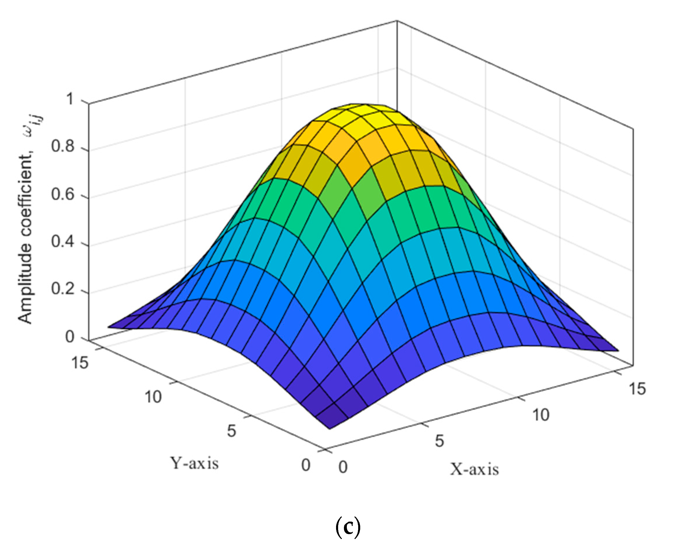
It is expected that the best tapered profile is obtained for square 2D arrays rather than rectangular ones because the longer sides of the array will have a lesser tapered profile at the array edges, which results in asymmetrical SLLs along the X and Y axis of the array. Figure 2a,b displays the two extended grids of a 1D Hamming window to extrapolate the 2D Hamming window as shown in Figure 2c using the cross-linear multiplication technique.

2.2. Adaptive Radial Tapering for 2D Tapered Window Extrapolation

In this approach, the tapered window is transformed to a distance tapered profile where the location of any element in the array is assumed to be in a continuum distance space with respect to the array center. This distance information is then converted to an element index in a virtual 1D array of a specific size to find the required weight by substituting in the 1D window function.
Assuming the 2D array geometry in Figure 1, where it lies in the XY plane with the interelement spaces normalized to half-wave distance and the first two 1D arrays of elements are located on the X and Y axes. The ij-th element indices ( i , j ) start with respect to the origin while the array center is located at the normalized distance coordinates ( ( I 1 ) / 2 , ( J 1 ) / 2 ).
The tapering coefficient for the rectangular array is extrapolated from a virtual 1D array window of size K by determining the element distance, ρ i , j , from the array center as follows:
ρ i , j = ( i I 1 2 ) 2 + ( j J 1 2 ) 2
where the maximum radial distance from the array center is given by:
ρ I , J = ( I 1 I 1 2 ) 2 + ( J 1 J 1 2 ) 2
or
ρ I , J = ( I 1 2 ) 2 + ( J 1 2 ) 2
which is the distance from the array center to any one of the array’s four corners.
The equivalent 1D array element index k ˙ i , j with respect to the array center and normalized to the maximum radial distance is given by:
k ˙ i , j = ρ i , j
with an equivalent virtual 1D array size of
K = ( I 1 ) 2 + ( J 1 ) 2
It is noted that the value of k ˙ i , j ranges from 0 to K / 2 where the elements located at radial distance ρ I , J have the lowest tapered coefficient while the maximum occurs at the nearest elements to the array center (i.e., k ˙ i , j = 0 ). Therefore, this approach of tapering is called “radial tapering” as it depends on the radial distance from the array center.
The application of radial tapering is more suited to square arrays than rectangular ones where radial distance is much larger than the array width, which means an incomplete tapered profile along the array’s shorter side resulting in a higher SLL. On the other hand, and even for square arrays, if we consider the maximum radial distance in (14) as the array tapering end, then the elements at the midpoints of the outermost sides of the array are less tapered, which also results in a higher SLL; therefore, the maximum distance in (14) should be adapted or modified as follows:
ρ ^ I , J = μ ( I 1 2 ) 2 + ( J 1 2 ) 2
and the adapted equivalent virtual 1D array size is, therefore, given by:
K ^ = μ ( I 1 ) 2 + ( J 1 ) 2
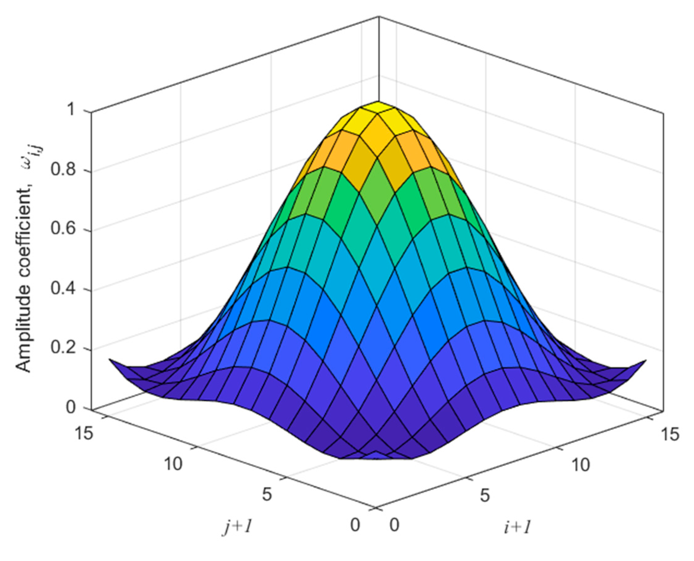
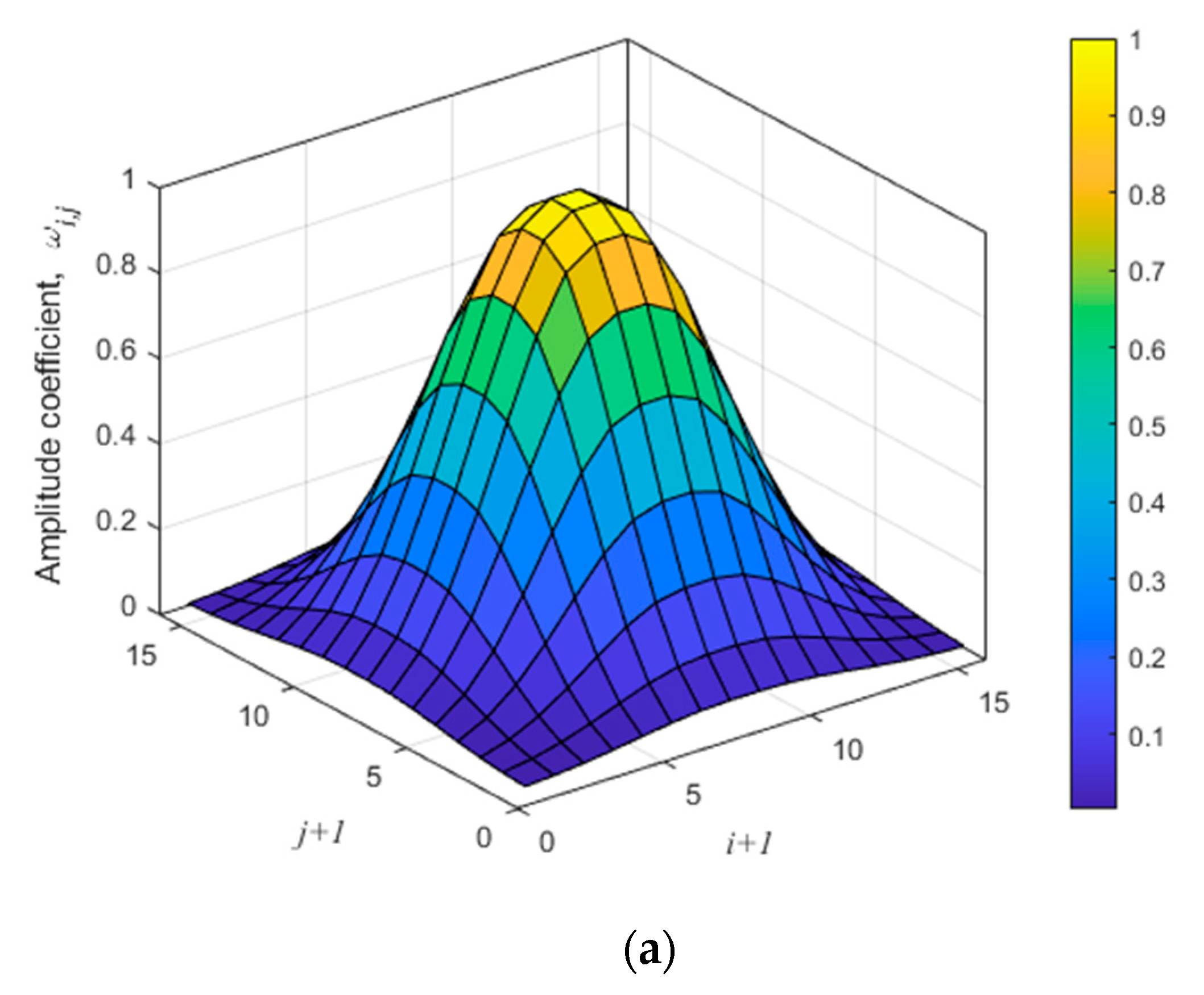
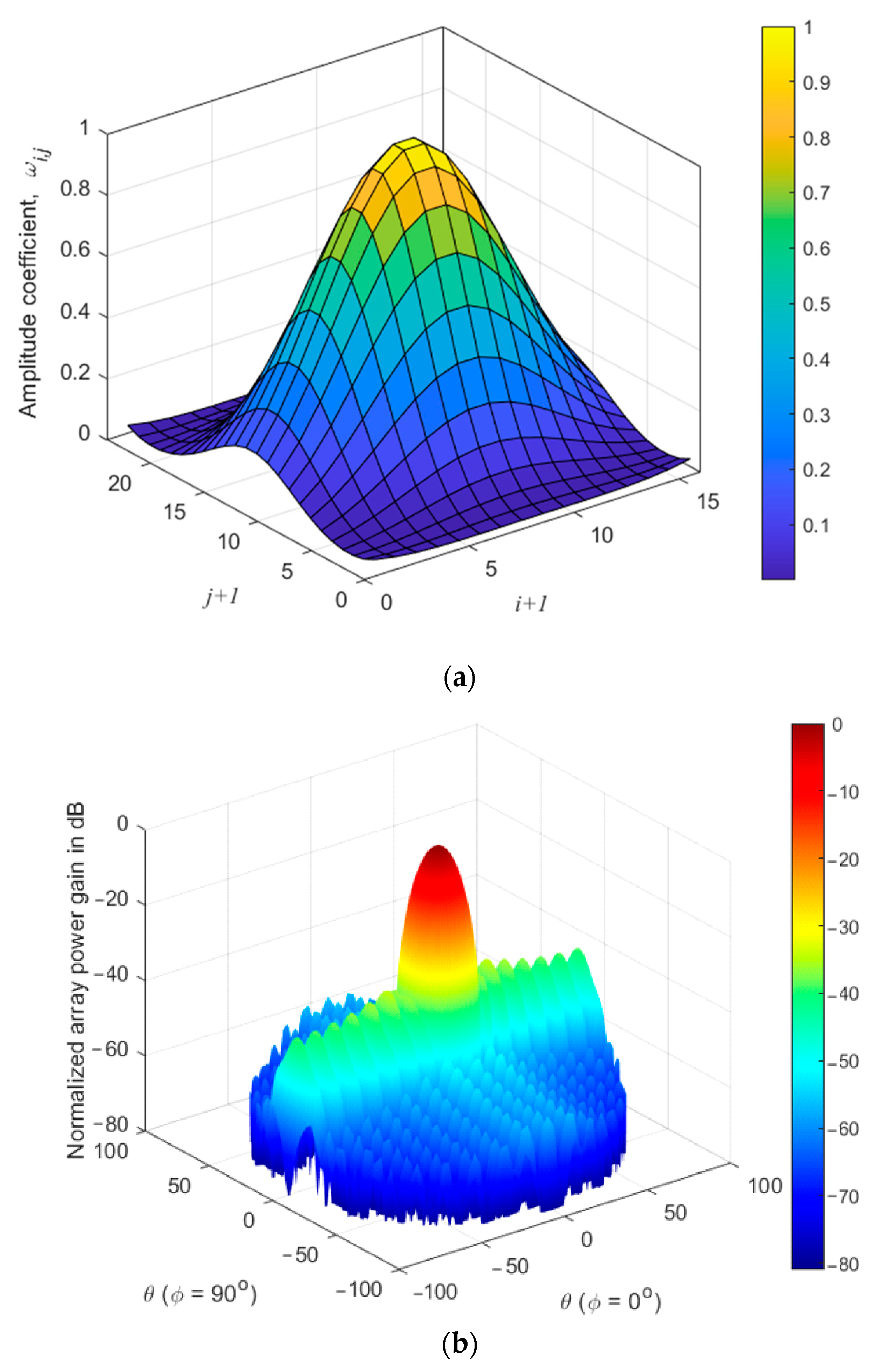
where μ is an edge tapering optimization factor for adjusting the array tapering profile for achieving minimum SLLs. Indeed, the edge tapering factor expands or shrinks the tapering window by reducing the higher values of the tapering coefficients at the mid-regions of array edges. However, adjusting the coefficients at the midpoints of the outermost side arrays affects the tapering coefficients at the array corners, which may exhibit some inversion in the tapered profile as shown in Figure 3, which displays the 2D radial tapered Hamming window for 16 × 16 array at μ = 0.85 .
As compared with the cross-linear Hamming window in Figure 2a, the cross-linear tapering always provides minimum amplitude coefficients at four of the array corner elements only with raised values at the middle of the four outer sides of the array. The impact of this adaptation is discussed in detail in the next section.

3. Results and Performance of the Proposed Techniques

3.1. Cross-Linear Tapering Extrapolation Performance

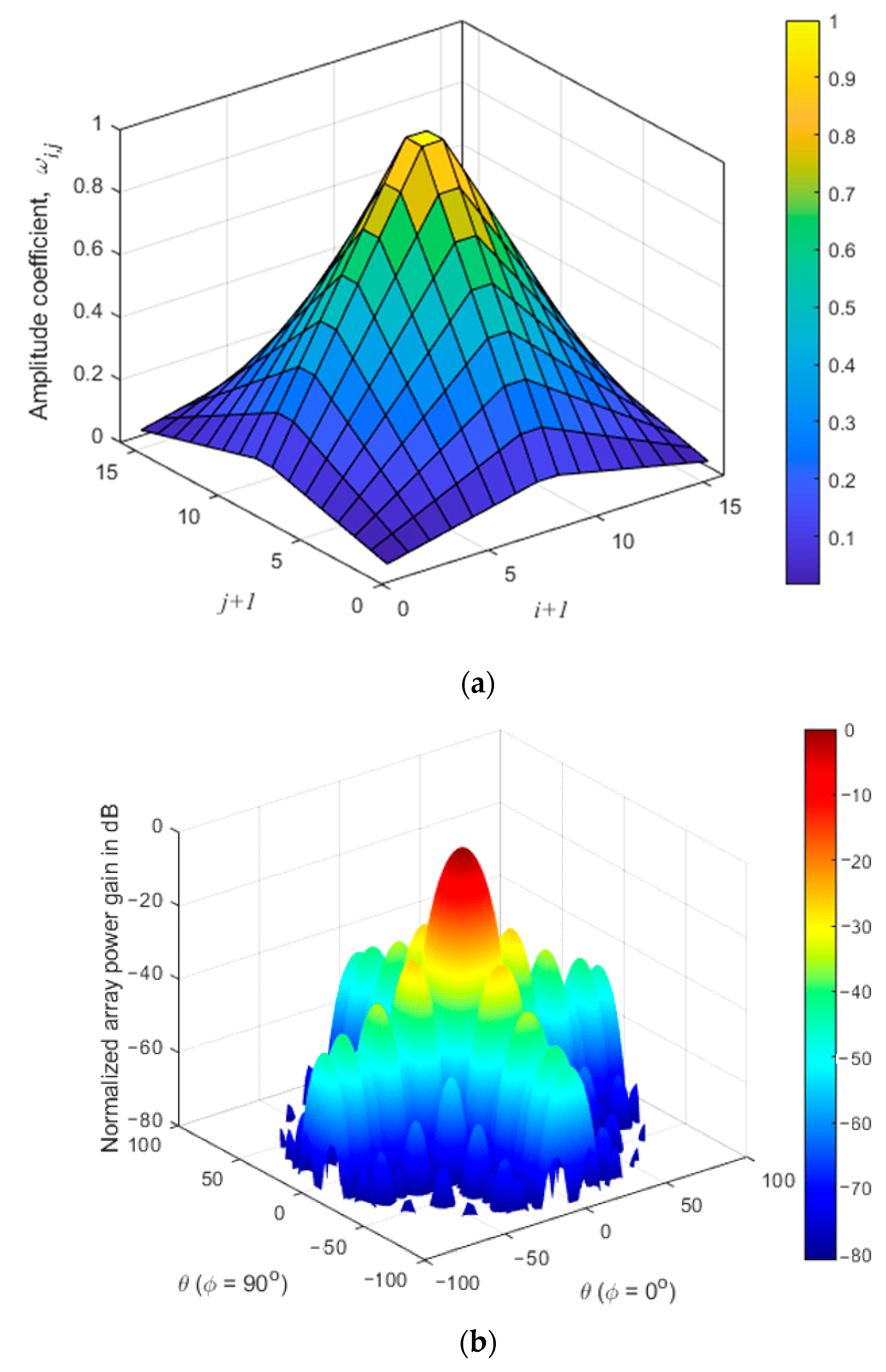
This section examines the performance of the direct cross-linear extrapolation technique for 2D antenna arrays of different sizes. Some well-known efficient 1D windows are extrapolated to 2D ones such as triangular (Bartlett), Hamming, cosine-square, and Blackman windows. The 2D triangular window for a 16 × 16 array using cross-linear extrapolation in shown in Figure 4a and the resulted normalized array power pattern is shown in Figure 4b. The impact of multiplication of the cross-linear windows along the X and Y axes results in nonlinear roll in the extrapolated window, especially along the array diagonals; however, the extrapolated windows along the two middle axes of symmetry perpendicular to the array sides retain the triangular linear variation. The resulted SLL is −26.34 dB.
The analysis of the extrapolated Hamming window is shown in Figure 5a, while the resulted normalized power pattern is demonstrated in Figure 5b. The Hamming window provides a slightly higher SLL compared with the triangular window, which is −26.2 dB.
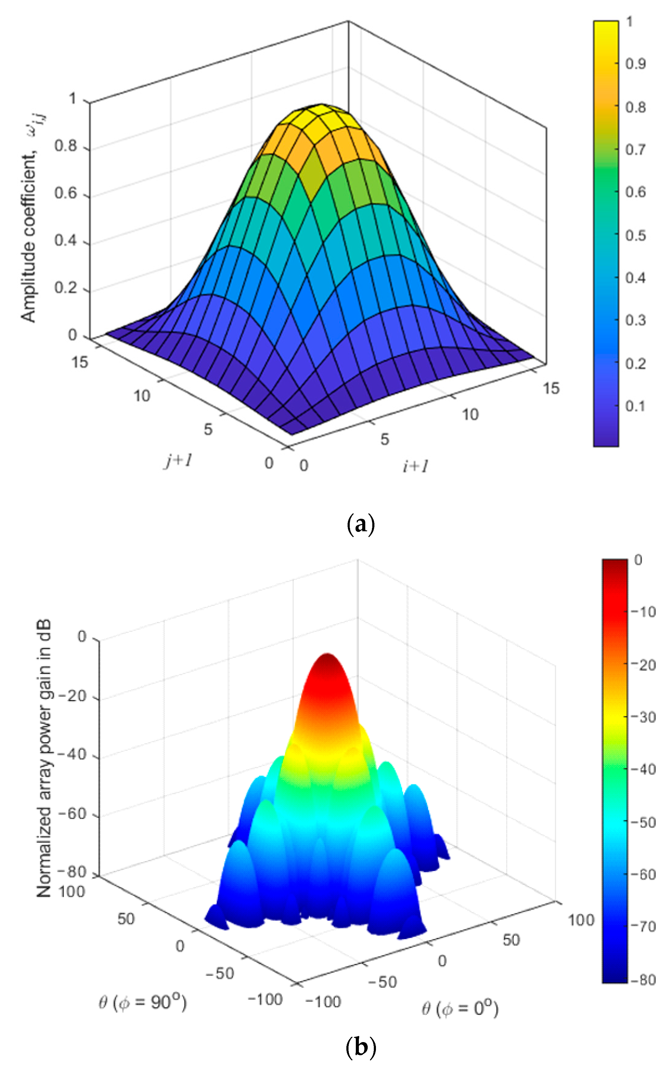
On the other hand, the cross-linear cosine-square window shown in Figure 6a slightly improves the SLL to −27.3 dB as depicted in Figure 6b, while the performance can be further improved using a cross-linear extrapolated Blackman window where the SLL is reduced to −35 dB at a sacrificed wider mainlobe beamwidth as shown in Figure 7a,b.
The performance analysis is extended to larger array sizes including the beamwidth variation for each of the four cross-linear extrapolated windows as listed in Table 1.
An interesting feature of the Hamming window at higher array sizes, such as 32 × 32, is that it provides lower SLLs compared to both triangular and cosine-square windows and with narrower beamwidth, which increases the array radiation efficiency. On the other hand, the Blackman window for 32 × 32 provides much lower SLLs with a slight increase in the beamwidth by 1 ° compared with the nearest efficient Hamming window.

3.2. Performance of Adaptive Radial Tapering

Although cross-linear 2D window extrapolation is straightforward, simple, and provides reasonable SLL reduction, the SLL performance can be further improved by optimizing the extrapolation technique using adaptive radial tapering. The best performance from radial tapering could be achieved for concentric circular arrays [17,18,19,20], while for 2D arrays, such as square or rectangular structures, the central distance varies according to the element location on the outermost side 1D arrays and, therefore, the tapered window is not completed at the middle of these side 1D arrays. Therefore, the adaptive radial tapering finds the optimum shrinking of the maximum radial distance, which is almost between the maximum radial distance (i.e., the radial distance from the array center to the array corners) and the distance between the array center to the middle point of the outermost side arrays. Therefore, the array edge tapering factor ( μ ) is optimized to minimize the SLLs for different array sizes and same four windows discussed in the previous section.
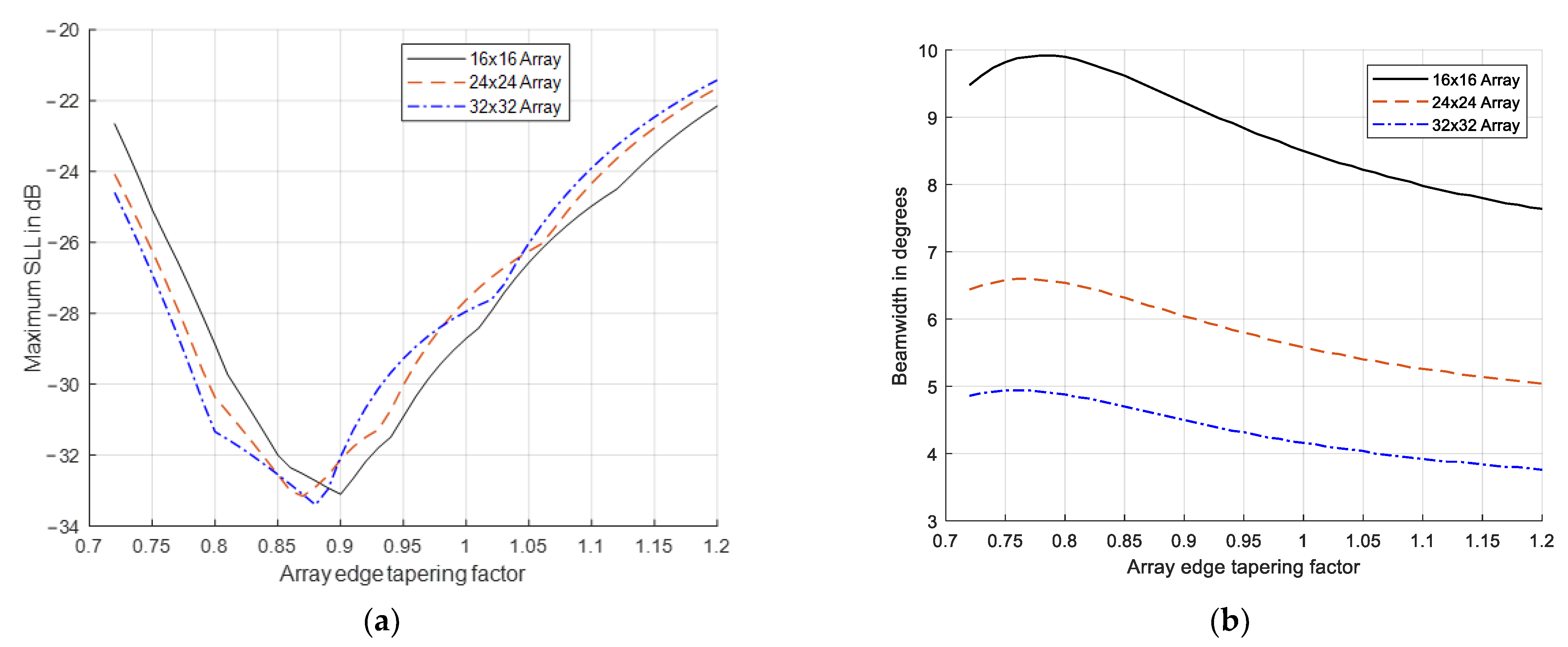
For the triangular radial tapered window, the optimization results are shown in Figure 8a for array sizes 16 × 16 , 24 × 24 , and 32 × 32 where the SLL is minimized, where the optimum values of μ range from 0.83 to 0.89. The beamwidth analysis of this window is shown in Figure 8b where increasing μ results in decreasing the mainlobe beamwidth because of the reduced tapered coefficients at higher values μ .
The optimization of the Hamming radial tapered window is shown in Figure 9a where the SLLs is improved and reduced to values around −33 dB according to the array size and with optimum values of μ ranging from 0.84 to 0.87. The beamwidth variation shown in Figure 9b for this window has an interesting feature, which is the slight variation with the edge tapering factor. This means that optimizing the Hamming radial tapered window slightly affects the beamwidth.
The optimization of the cosine-square window provides similar SLLs as in the Hamming radial tapering but with slightly higher beamwidth dependency on μ as shown in Figure 10a,b, respectively. The optimum values of μ in this case range from 0.87 to 0.9 according to the array size.
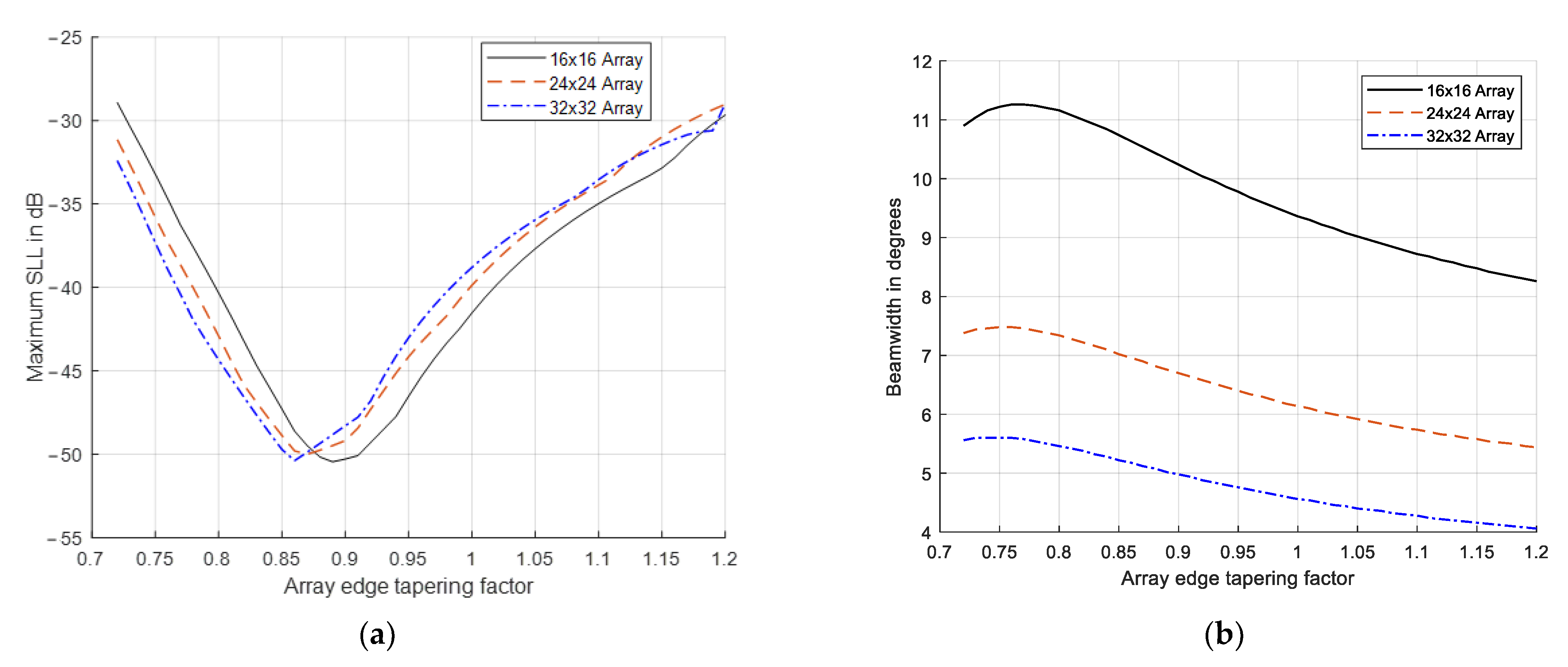
Finally, the Blackman radial tapered window optimization is carried out for the three array sizes as shown in Figure 11a,b where there is a significant SLL reduction with a slightly increased beamwidth compared to the three previous optimized windows. The optimum SLL for the three array sizes is minimized to −50 dB at values of μ ranging between 0.86 and 0.89.
The optimization results of the radial tapering extrapolation for the four different windows are summarized in Table 2, showing the optimum value of μ at which the SLL is minimized along with the resulted mainlobe beamwidth.
From the optimization results in Table 2, it is clear that the radial tapered Blackman window provides significant improvements in SLLs where −50 dB is achieved irrespective of the array size and with a slightly increased mainlobe beamwidth. Additionally, the optimum Hamming radial tapered window almost provides similar SLLs compared with the cosine-square one but at lower beamwidth values, while the triangular window provides higher SLLs with some higher beamwidth values, especially for smaller array sizes.
The optimum values of μ for the different extrapolated windows range from 0.83 to 0.96 as shown in Figure 12 according mainly to the array size. There is a general behavior for the optimum value of μ where it generally decreases with increasing array size, and most array sizes have approximately an average optimum μ value of 0.87, which is almost at midrange between the maximum normalized array radial distance and the normalized normal distance from array center to the midpoint of the outermost array side. In addition, it has been noted that there is a common behavior with the windows that have cosine and cosine-square profiles rather than the triangular window. The triangular window has more variation for the optimum μ with the array size than the other windows, while Blackman and cosine-square windows have an almost near profile as they both have squared cosine terms.

3.3. Performance of the Proposed Techniques for Rectangular Arrays

In this section, we will examine the two proposed techniques for rectangular array structures. The cross-linear tapering technique guarantees the tapered profile along the array edges due to the Hadamard matrix multiplication in (9) while the adaptive radial tapering requires almost equal contours over the array to work effectively. Therefore, it is expected that the radial tapering will be incomplete along the shorter edge or width of the array, which results in a higher SLL in one direction than the other perpendicular one.
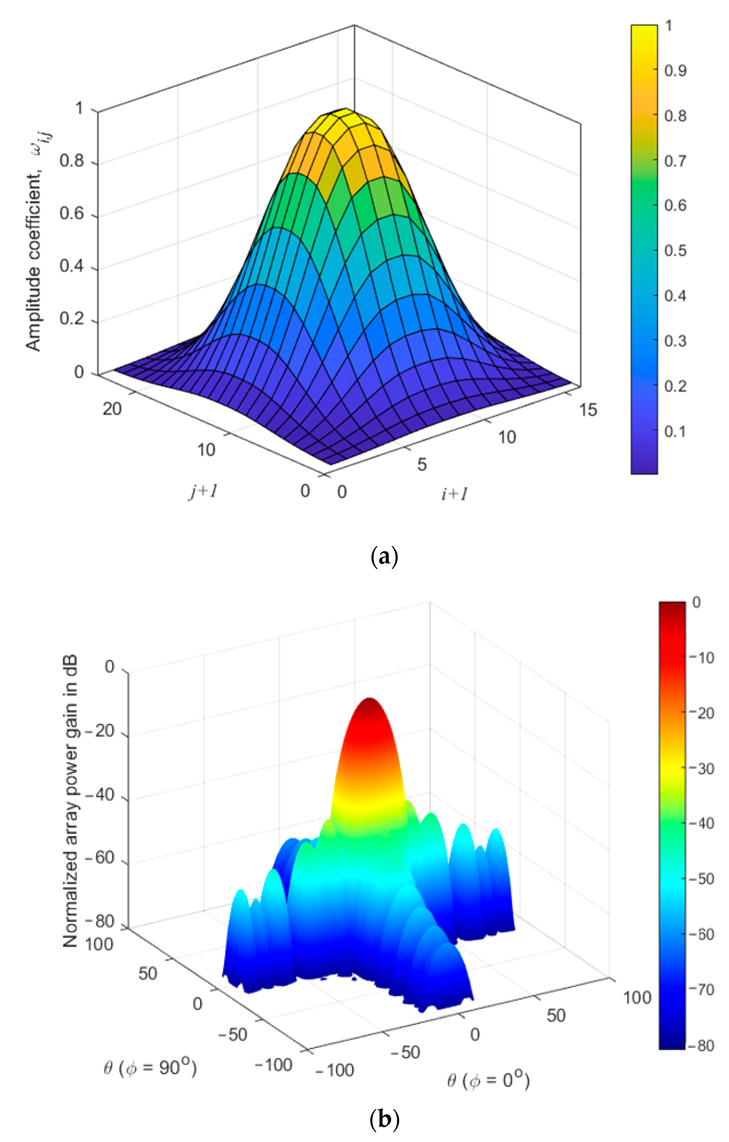
Figure 13a displays the cross-linear extrapolated Blackman window for a 16 × 24 array while Figure 13b shows the normalized power pattern where a maximum SLL of −34 dB results. On the other hand, the radial tapering of this array at μ = 0.86 results in the 2D tapered shown in Figure 14a and the corresponding normalized power pattern in Figure 14b where there are some higher values for the coefficients along the array longer side while the other shorter one still provides the lowest coefficients. Therefore, the normalized power pattern shown in Figure 14b has two unequal planes of SLLs where the plane along the shorter side has higher SLL values than the loner one. In this case, we may compromise the required SLL where it is more important to achieve lower SLL values along the length of the array than its width.
The radial tapering provides almost the same maximum −34 dB SLL as in the cross-linear case while much deeper −51 dB SLL is achieved along the perpendicular plane.
Therefore, we can conclude that radial tapering of 2D arrays is more efficient for square arrays where it provides symmetrical deeper SLL values than the cross-linear case, while for rectangular arrays, radial tapering is efficient only in the plane of the array length than that along its width.

3.4. Simulation Results of the Proposed Techniques for Crossed-dipole 2D Arrays

In this section, the proposed techniques are examined for 2D crossed-dipole arrays using the MATLAB Antenna Toolbox v 4.2 [21].
The simulation parameters include the following information:
-
Operating frequency: 5 GHz;
-
Dipole length: 0.476 λ ;
-
Antenna inter-separation distance: λ / 2 ;
-
Dipole width: 0.02 λ .
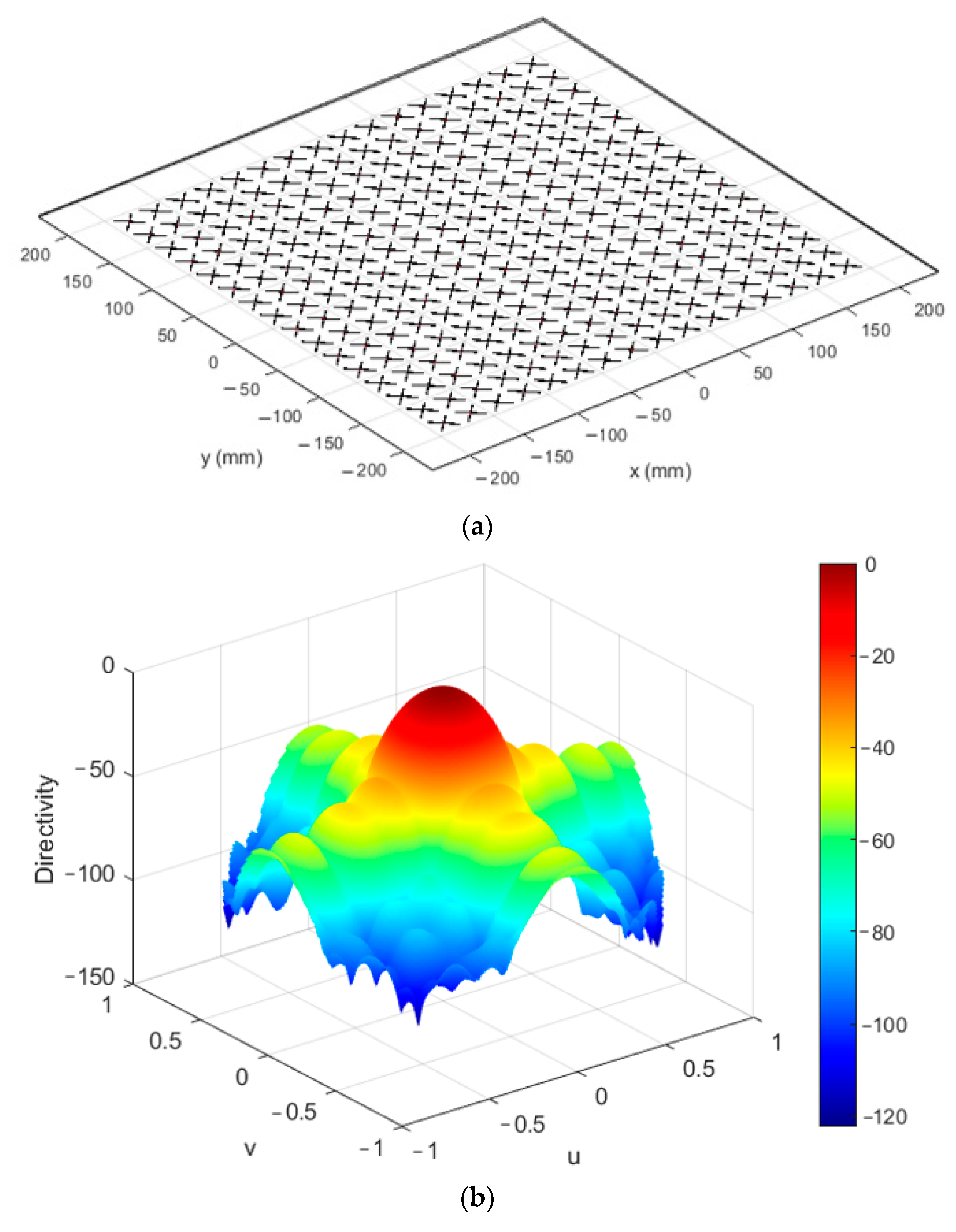
The impact of mutual coupling also has been included in the study, and the array structure along with the normalized beam pattern are shown in in Figure 15a–c, respectively for the two proposed techniques using the Blackman window for a 20 × 20 array.
The normalized power pattern in Figure 15b depicting an SLL of −34 dB has been achieved using cross-linear tapering, while it is down to −53 dB for the adaptive radial tapering as shown in Figure 15c. The simulation results from these two figures have shown that an even lower SLL can be obtained due to the incomplete isotropic power pattern of the crossed-dipole antenna element.

4. Discussions

The capabilities of window functions to reduce the SLLs are extended in this paper for 2D arrays using the same formulas of 1D windows by two efficient extrapolation techniques. The results in the previous sections have shown that the adaptive radial tapering can be optimized to achieve the lowest SLL for any array size compared to the direct cross-linear tapering technique. The radial tapering converts the element index tapering to distance tapering over the array grid by finding the radial distance from the array center to the coordinates of each antenna element. The optimization process tries to taper the less-tapered elements at the midpoints of the array’s outer sides by shrinking the array radial distance by the array’s edge factor. Therefore, if the SLLs required in the power pattern are in the range of that obtained by cross-linear tapering, it will be better to apply cross-linear tapering as it is straightforward and does not require any optimization and provides a lower beamwidth. On the other hand, if the SLLs are required to be less than −30 dB, then the adaptive radial tapering is the right choice, where there are many 1D windows that can be extrapolated to achieve these levels at a slightly increased beamwidth. In addition, we can use a global average value of μ for each 1D window without going through the optimization process to directly find the extrapolated 2D weights, and although the obtained SLLs are not the lowest ones, it will still be lower than the direct cross-linear technique. For example, the extrapolated Blackman window has an average optimum μ of 0.865, which provides a maximum of 3 dB variation from the lowest sidelobe value for most array sizes, which is less than −47 dB.
For massive 2D arrays of 40 × 40 elements or more, the optimum μ converges to approximately 0.85, which can be used regardless of the type of extrapolated window. On the other hand, the tapered windows that adopt cosine functions or their powers have almost the same optimization behavior as shown in Figure 12. For example, the Hamming, cosine-square, and Blackman windows have the same optimum value of μ which is 0.87 for the 24 × 24 antenna array.

5. Conclusions

The process of extrapolating 2D tapered window functions from 1D ones has been achieved in this paper by two techniques. The first proposed extrapolation technique is the cross-linear tapering, which finds the 2D weights by multiplying 2D cross grids of repeated 1D functions in the two directions of the planar array. This technique is straightforward and does not require optimization and, therefore, is suitable for fast manipulation of 2D arrays and provides SLLs of less than −26 dB for most window functions. The second proposed radial tapering extrapolation technique finds the 2D function by converting the element location to an index in a virtual 1D array calculated from the radial distance of the element with respect to the array center. The technique has been optimized to achieve deeper SLLs for any tapered window by adapting the edge tapering factor of the array to reduce the coefficients along the mid-region of the outermost sides of the planar arrays. It has been found that the average optimum value of the edge tapering factor is approaching 0.85, especially for massive arrays for most window functions and regardless of the array size. Additionally, the adaptive radial tapering technique has achieved SLLs of less than −50 dB using the Blackman window for all array sizes.

Author Contributions

Conceptualization, Y.A.; methodology, Y.A.; software, Y.A. and F.A.; validation, Y.A. and F.A.; formal analysis, Y.A.; investigation, F.A.; writing—original draft preparation, Y.A.; writing—review and editing, F.A. and Y.A.; visualization, Y.A.; funding acquisition, Y.A. All authors have read and agreed to the published version of the manuscript.

Funding

Taif University Researchers Supporting Project number (TURSP-2020/161), Taif University, Taif, Saudi Arabia.

Acknowledgments

The authors would like to thank Taif University Researchers Supporting Project number (TURSP-2020/161), Taif University, Taif, Saudi Arabia, for supporting this work.

Conflicts of Interest

The authors declare no conflict of interest.

References

  1. Pałczyński, K.; Śmigiel, S.; Gackowska, M.; Ledziński, D.; Bujnowski, S.; Lutowski, Z. IoT Application of Transfer Learning in Hybrid Artificial Intelligence Systems for Acute Lymphoblastic Leukemia Classification. Sensors 2021, 21, 8025. [Google Scholar] [CrossRef] [PubMed]
  2. Cray, B.A.; Kirsteins, I. A Comparison of Optimal SONAR Array Amplitude Shading Coefficients. Acoustics 2019, 1, 808–815. [Google Scholar] [CrossRef] [Green Version]
  3. Said, O.; Albagory, Y.; Nofal, M.; Al Raddady, F. IoT-RTP and IoT-RTCP: Adaptive Protocols for Multimedia Transmission Over Internet Of Things Environments. IEEE Access 2017, 5, 16757–16773. [Google Scholar] [CrossRef]
  4. Hasan, M.Z.; Al-Rizzo, H. Beamforming Optimization in Internet of Things Applications Using Robust Swarm Algorithm in Conjunction with Connectable and Collaborative Sensors. Sensors 2020, 20, 2048. [Google Scholar] [CrossRef] [Green Version]
  5. Sabban, A. Active compact wearable body area networks for wireless communication, medical and IoT applications. Appl. Syst. Innov. 2018, 1, 46. [Google Scholar] [CrossRef] [Green Version]
  6. Ruiz-de-Azua, J.A.; Garzaniti, N.; Golkar, A.; Calveras, A.; Camps, A. Towards Federated Satellite Systems and Internet of Satellites: The Federation Deployment Control Protocol. Remote Sens. 2021, 13, 982. [Google Scholar] [CrossRef]
  7. Mujkic, S.; Kasapovic, S.; Abuibaid, M. Energy-efficient resource optimization for massive mimo networks considering network load. Comput. Mater. Contin. 2022, 71, 871–888. [Google Scholar]
  8. Larsson, E.G.; Edfors, O.; Tufvesson, F.; Marzetta, T.L. Massive MIMO for next generation wireless systems. IEEE Commun. Mag. 2014, 52, 186–195. [Google Scholar] [CrossRef] [Green Version]
  9. Bogale, T.E.; Le, L.B. Massive MIMO and mmwave for 5G wireless HetNet: Potential benefits and challenges. IEEE Veh. Technol. Mag. 2016, 11, 64–75. [Google Scholar] [CrossRef]
  10. Mohammed, S.L.; Alsharif, M.H.; Gharghan, S.K.; Khan, I.; Albreem, M. Robust Hybrid Beamforming Scheme for Millimeter-Wave Massive-MIMO 5G Wireless Networks. Symmetry 2019, 11, 1424. [Google Scholar] [CrossRef] [Green Version]
  11. Riviello, D.G.; Di Stasio, F.; Tuninato, R. Performance Analysis of Multi-User MIMO Schemes under Realistic 3GPP 3-D Channel Model for 5G mmWave Cellular Networks. Electronics 2022, 11, 330. [Google Scholar] [CrossRef]
  12. Artiga, X.; Perruisseau-Carrier, J.; Pérez-Neira, A.I. Antenna array configurations for massive MIMO outdoor base stations. In Proceedings of the 2014 IEEE 8th Sensor Array and Multichannel Signal Processing Workshop (SAM 2014), A Coruna, Spain, 22–25 June 2014; pp. 281–284. [Google Scholar]
  13. Nofal, M.; Aljahdali, S.; Albagory, Y. Tapered beamforming for concentric ring arrays. AEU-Int. J. Electron. Commun. 2012, 67, 58–63. [Google Scholar] [CrossRef]
  14. Rohit, H.R.; Sachin, B.S.; Aditya, P.; Bhishm, T.; Premananda, B.S. Performance evaluation of various beamforming techniques for phased array antennas. In Proceedings of the 11th International Conference on Computing, Communication and Networking Technologies (ICCCNT), Kharagpur, India, 1–3 July 2020; pp. 1–6. [Google Scholar]
  15. Deepshikha, A.R.; Raut, A.; Bazil Raj, A.A. Signal Processing for Digital Beamforming on Transmit in MIMO Radar. In Proceedings of the Second International Conference on Inventive Research in Computing Applications (ICIRCA), Coimbatore, India, 15–17 July 2020; pp. 1106–1111. [Google Scholar]
  16. Prabhu, K.M.M. Window Functions and Their Applications in Signal Processing; Taylor & Francis: Abingdon, UK, 2014. [Google Scholar]
  17. Aljahdali, S.; Nofal, M.; Albagory, Y. A modified array processing technique based on Kaiser window for concentric circular arrays. In Proceedings of the 2012 International Conference on Multimedia Computing and Systems, ICMCS 2012, Tangiers, Morocco, 10–12 May 2012. [Google Scholar]
  18. Albagory, Y. Sectorized hamming concentric circular arrays for stratospheric platforms cellular design. Int. J. Comput. Netw. Inf. Secur. 2013, 5, 21–27. [Google Scholar] [CrossRef] [Green Version]
  19. Albagory, Y.; Said, O. Concentric Circular Arrays for Stratospheric High-Altitude Platforms Wireless Sensor Networks. Wirel. Pers. Commun. 2015, 81, 593–605. [Google Scholar] [CrossRef]
  20. Alsharif, S.; Saeed, R.A.; Albagory, Y. An efficient haps cross-layer design to mitigate covid-19 consequences. Intell. Autom. Soft Comput. 2022, 31, 43–59. [Google Scholar] [CrossRef]
  21. Available online: https://www.mathworks.com/products/matlab.html (accessed on 6 May 2022).
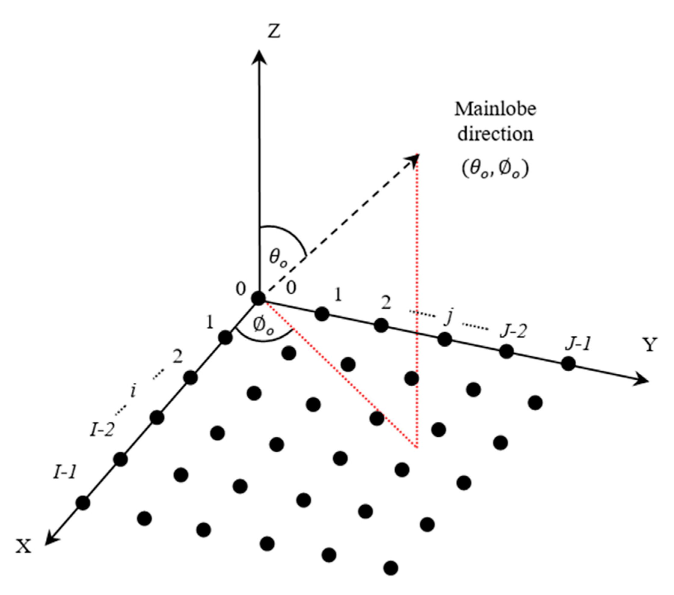
Figure 1. General uniform 2D antenna array on the XY plane with elements indexing.
Electronics 11 01995 g001
Figure 2. (a) Hamming window for linear arrays along X-direction, (b) Hamming window for linear arrays along Y-direction, (c) 2D extrapolated Hamming window for 16 × 16 array using cross-linear tapering of weights in (a,b).
Electronics 11 01995 g002aElectronics 11 01995 g002b
Figure 3. 2D extrapolated Hamming window for 16 × 16 array using radial tapering at μ = 0.85 .
Electronics 11 01995 g003
Figure 4. (a) 2D cross-linear extrapolated triangular window for 16 × 16 array. (b) Normalized array power pattern.
Electronics 11 01995 g004
Figure 5. (a) 2D cross-linear extrapolated Hamming window for 16 × 16 array. (b) Normalized array power pattern.
Electronics 11 01995 g005
Figure 6. (a) 2D cross-linear extrapolated cosine-square window for 16 × 16 array. (b) Normalized array power pattern.
Electronics 11 01995 g006
Figure 7. (a) 2D cross-linear extrapolated Blackman window for 16 × 16 array. (b) Normalized array power pattern.
Electronics 11 01995 g007aElectronics 11 01995 g007b
Figure 8. (a) Optimizing radial tapered triangular window at different array sizes. (b) Beamwidth variation with the array edge tapering factor at different array sizes.
Electronics 11 01995 g008
Figure 9. (a) Optimizing radial tapered Hamming window at different array sizes. (b) Beamwidth variation with the array edge tapering factor at different array sizes.
Electronics 11 01995 g009
Figure 10. (a) Optimizing radial tapered cosine-square window at different array sizes. (b) Beamwidth variation with the array edge tapering factor at different array sizes.
Electronics 11 01995 g010
Figure 11. (a) Optimizing radial tapered Blackman window at different array sizes. (b) Beamwidth variation with the array edge tapering factor at different array sizes.
Electronics 11 01995 g011
Figure 12. Optimum edge tapering factor variation with the array size for different radial tapering extrapolated 2D windows.
Electronics 11 01995 g012
Figure 13. (a) 2D cross-linear extrapolated cosine-square window for 16 × 24 array. (b) Normalized array power pattern.
Electronics 11 01995 g013
Figure 14. (a) 2D radial tapering extrapolated cosine-square window for 16 × 24 array. (b) Normalized array power pattern.
Electronics 11 01995 g014
Figure 15. (a) 2D 20 × 20 crossed-dipole antenna array in the XY plane, (b) normalized power pattern for Blackman cross-linear tapered array, and (c) normalized power pattern for Blackman radial-tapered array at μ = 0.86 .
Electronics 11 01995 g015aElectronics 11 01995 g015b
Table 1. Cross-linear 2D windows performance at different array sizes.
Maximum SLL in dBBeamwidth in Degrees
Array Size16 × 1624 × 2432 × 3216 × 1624 × 2432 × 32
Triangular window(Figure 4)−26.34−26.5−26.478.665.884.44
Hamming window (Figure 5)−26.2−29.4−31.378.265.724.38
Cosine-square window (Figure 6)−27.3−28.6−29.219.546.544.96
Blackman window (Figure 7)−35−38.66−41.629.786.95.34
Table 2. Optimum radial tapering of 2D windows at different array sizes.
Maximum SLL in dBBeamwidth in Degrees
Array Size16 × 1624 × 2432 × 3216 × 1624 × 2432 × 32
Triangular window (Figure 8)−27.56 dB−27.63 dB−27.8 dB8.4664.12
μ = 0.89 μ = 0.83 μ = 0.89 μ = 0.89 μ = 0.83 μ = 0.89
Hamming window (Figure 9)−32.18 dB−33.33 dB−33.6 dB8.465.64.24
μ = 0.87 μ = 0.87 μ = 0.84 μ = 0.87 μ = 0.87 μ = 0.84
Cosine-square window (Figure 10)−33.1 dB−33.11 dB−33.4 dB9.226.24.58
μ = 0.9 μ = 0.87 μ = 0.88 μ = 0.81 μ = 0.87 μ = 0.88
Blackman window (Figure 11)−50.45 dB−50 dB−50.38 dB10.346.95.18
μ = 0.89 μ = 0.87 μ = 0.86 μ = 0.89 μ = 0.87 μ = 0.86
Publisher’s Note: MDPI stays neutral with regard to jurisdictional claims in published maps and institutional affiliations.