You are currently viewing a new version of our website. To view the old version click .
Electronics
  • Article
  • Open Access

23 December 2021

Physical Layer Secrecy by Power Splitting and Jamming in Cooperative Multiple Relay Based on Energy Harvesting in Full-Duplex Network

,
,
,
,
,
,
,
,
and
1
School of Information Engineering, Zhengzhou University, 100, Science Avenue, Zhengzhou 450001, China
2
Faculty of Aviation Sciences, Amman Arab University, Amman 11953, Jordan
3
Electrical Engineering Department, Balochistan University of Information Technology, Engineering and Management Sciences, Quetta 87300, Pakistan
4
School of Computer Science and Engineering, Nanjing University of Science and Technology, Nanjing 210094, China
This article belongs to the Special Issue Innovative Antenna Systems: Challenges, Developments, and Applications

Abstract

In this article, we investigated the secrecy performance of a three-hop relay network system with Power Splitting (PS) and Energy Harvesting (EH). In the presence of one eavesdropper, a signal is transferred from source to destination with the help of a relay. The source signal transmits in full-duplex (FD) mood, jamming the relay transfer signals to the destination. The relay and source employ Time Switching (TS) and Energy Harvesting (EH) techniques to obtain the power from the power beacon. In this study, we compared the Secrecy Rate of two Cooperative Schemes, Amplify and Forward (AF) and Decode and Forward (DF), for both designed systems with the established EH and PS system. The Secrecy Rate was improved by 50.5% in the AF scheme and by 44.2% in the DF scheme between the relay and eavesdropper at 40 m apart for the proposed system in EH and PS. This simulation was performed using the Monto Carlo method in MATLAB.

1. Introduction

Due to the broadcast nature of wireless communication, information transmission is not secure. By utilizing the physical properties of the wireless communication, physical layer security (PLS) aids in ensuring secure communication [1]. There are several relaying schemes that can be employed to improve PLS, but two of the most popular are Cooperative Schemes DF and AF in wireless communication techniques [2,3]. The nodes in communication networks are powered by putting separate batteries inside them; however, in some circumstances, replacing or recharging those batteries is not recommended [4]. The Energy-Harvesting (EH) approach [5,6,7] can be used to solve this problem. It also contributes to the improved reliability and low-maintenance monitoring of the system. Additionally, as the number of communication devices grows, it is necessary to shift toward more energy-efficient systems.
In [8], a scheme was presented to check the secrecy level in a cooperative compressed sensing amplify and forward (CCS-AF) wireless network in the presence of eavesdroppers and receive radio frequency signals consisting of Power Splitting Relaying (PSR). Similarly, in [9], the physical layer secrecy efficiency of Radio Frequency Energy Harvesting (RF-EH) in the Rayleigh fading environment was investigated. While the preceding work focuses on two-hop relaying systems, it is worth looking at secure communication in multi-hop relaying systems with more than two hops.
In this work, the authors investigate a three-hop relaying system with a single relay active at each individual hop, where one source–destination pair tries to communicate securely in the presence of one eavesdropper. Each relay node operates using cooperative communication between AF and DF, and each node has a single antenna. Due to propagation loss, each relay and the destination only hear their previous nearby nodes in the standard multi-hop relaying paradigm in [10,11]. This was further analyzed by various authors in a two-way relay network to improve the Secrecy Rate versus eavesdropping attack [12,13,14,15].
Ref [12] investigated the secrecy performance of a proposed Single-Hop Relay system and found an improvement in the performance of EH of 8.89% for the AF relay and of 9.83% for the DF Relay between the eavesdropper and the relay. Ref [13] investigated the secrecy performance of a Single-Hop Relay Network, and observed a performance improvement of 30.47% for the DF Cooperative Scheme and of 23.63% for the AF Cooperative Scheme between the eavesdropper and the relay. Ref [14] investigated the secrecy performance of a Single-Hop Relay Network, and the results were an 11.9% improvement for the AF Single-Hop Relay Network and of 42.86% for the DF Single-Hop Relay Network. Ref [15] investigated the secrecy performance of a Wireless Relay Network and found 40% performance improvement for DF in the Half-Duplex Relay (HDR) Network and 41% for the AF Half-Duplex Relay (HDR) Network. However, in our study, the results included an improvement in the secrecy performance of the three-hop wireless relay system, with EH and PS being improved by 50.5% for the AF Cooperative Scheme and by 44.2% for DF between the eavesdropper and R1 and R2 in full duplex mood.
The authors conducted a review of various studies focused on the secrecy of wireless communication transmission to eavesdroppers in the relaying node, where the cooperative communication schemes used in the DF and AF relaying protocols were analyzed and equated with different systems. The proposed cooperative jamming in [16] was based on an analysis of the Secrecy Rate, where a number of relays were authorized to communicate with each other and prevent the eavesdropper from attacking. The cooperation of multi-users was employed to examine the physical layer security by using the proposed noise-forwarding scheme. In [17], a full-duplex relay network was presented to improve the physical layer security in the multi-hop relaying system, and a geometric programming (GP) method was applied to solve the transmitted power allocation problem. In summary, the contributions of the paper are as follows.
  • This paper presents an investigation of a three-hop relaying system with a single relay active at each individual hop, where one source–destination pair tries to communicate securely in the presence of one eavesdropper.
  • Each relay node operates in the AF and DF modes, and each node has a single antenna. Due to propagation loss, each relay and the destination only hear their previous nearby nodes in the standard multi-hop relaying paradigm.
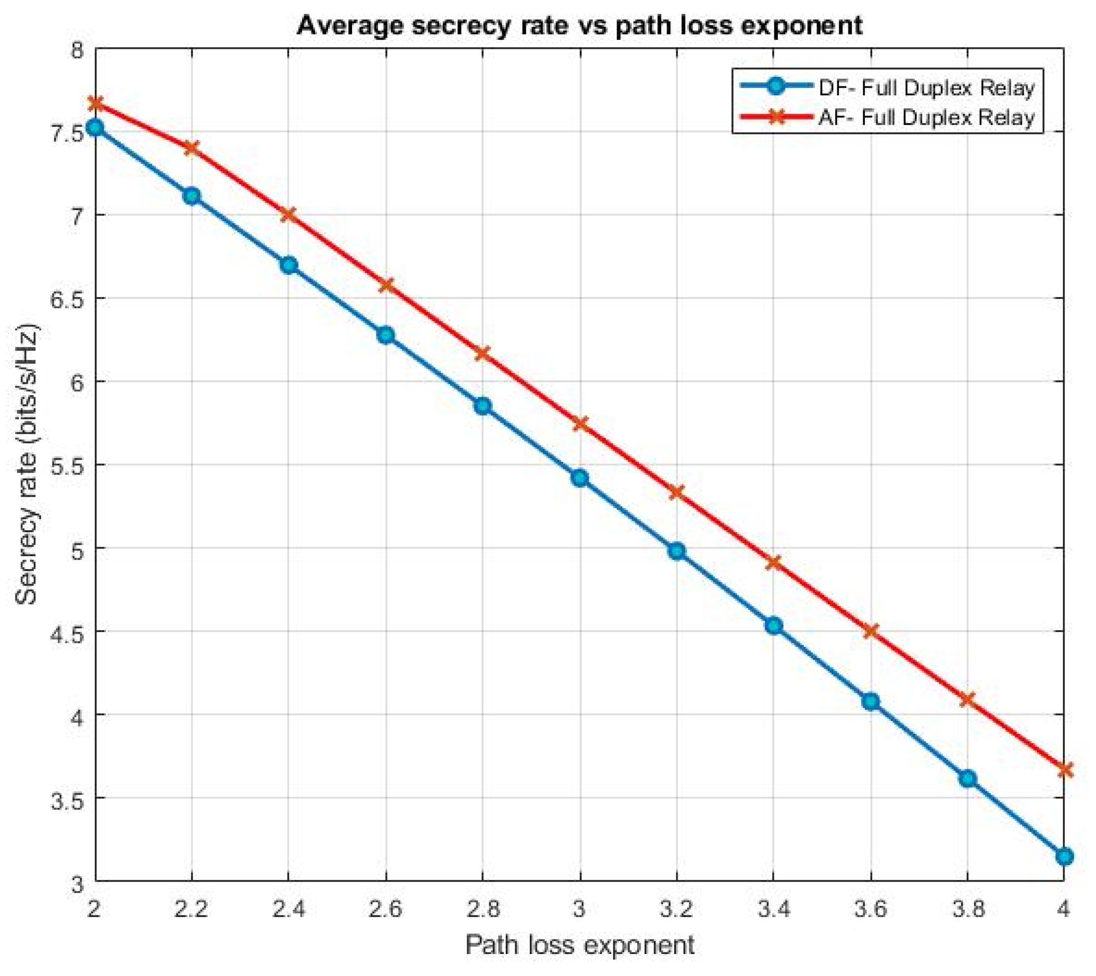
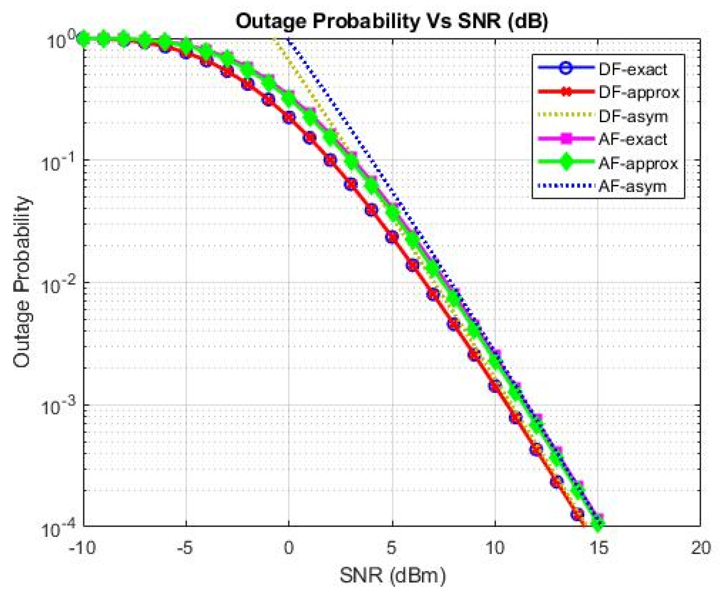
  • The Secrecy Rates of two Cooperative Schemes, Amplify and Forward (AF) and Decode and Forward (DF), for both proposed systems are compared with those of the conventional Energy-Harvesting System, including an examination of the performance of the Outage Probability for proposed EH system.
  • In calculation, we extract accurate Secrecy Outage Probability (SOP) in a one-integral format and the closed-format asymptotic SOP for higher average Signal Noise Ratio (SNR).

1.1. Paper Organization

This article is organized into various sections; all the sections are divided into different portions and each section contains subsections. Table 1 summarizes paper flow.
Table 1. The following table shows the paper’s contents.

2. System Model

Figure 1 shows the three-hop relay network with a single eavesdropper (E) utilizing EH. It consists of a source S, Relay R1, R2, Distention node D and an eavesdropper E. This three hop relay network is powered up by a power beacon (B). Let H × SR1, H × R1E, H × R2E, H × R2D, H × BR1, and H × BR2 represent the Complex Channel acquired from the network shown in Figure 1. The noise in the network shown in Figure 1 is supposed to be complex additive white Gaussian noise (AWGN) with a mean of zero, the variance σ2 and no Self-Interference Signal (SIC). Further, the relay exhibits Full Duplex (FD) mood in the designed model. Each relay performs in the AF and DF modes to amplify and decode the signal from the previous node and forward the re-encoded signal to the next node.
Figure 1. System model of the secrecy relay network.

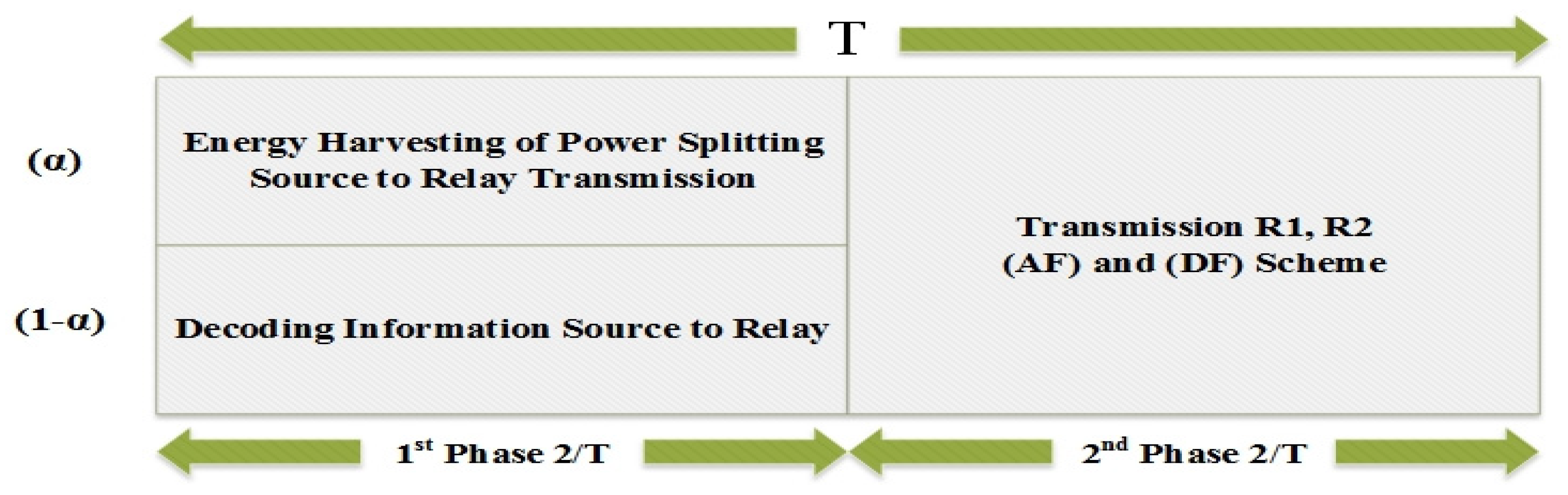
2.1. Power Splitting and Energy Harvesting Technique

In the present-design system, S, R1 and R2 harvest energy from the power beacon and send it to D, where it is used for signal transmission. Figure 2 illustrates Power Switching and Energy Harvesting Schemes; whereas T is the time duration divided into two parts. The transmitted signal splits into two parts during the first slot and depends on the power splitting ratio of the power. The first phase is transferred by the source for Energy-Harvesting purposes and the second phase is applied to transfer signal to the source. The second time slot is used for transmitting the signal to destination D.
Figure 2. Power-splitting-, Energy-Harvesting- and time-switching-based relaying protocol.
In this equation, the energy harvested from R1 and R2 is expressed as.
E R 1 = η α ρ P B | h × B R 1 | 2   T 2
  E R 2 = η α ρ P B | h × B R 2 | 2   T 2
where α represents the signal portion for EH. Thus, the power transferred by R1 and R2 is represented by:
P R 1 = η   α ρ   P B | h × B R 2 | 2 ( 1 α )
P R 2 = η   α ρ   P B | h × B R 2   | 2 ( 1 α )
whereas the efficiency of the coefficient of this process in terms of energy transference is represented by 0 < η < 1, and the power sent through beacon node is represented by PB and 0 < α < 1. T represents the time taken to transmit the specific block S to D. The source S, and R1 and R2, harvest energy for a B time duration of α T. The power transmitted via S, R1 and R2 in this proposed system is embodied by [11].

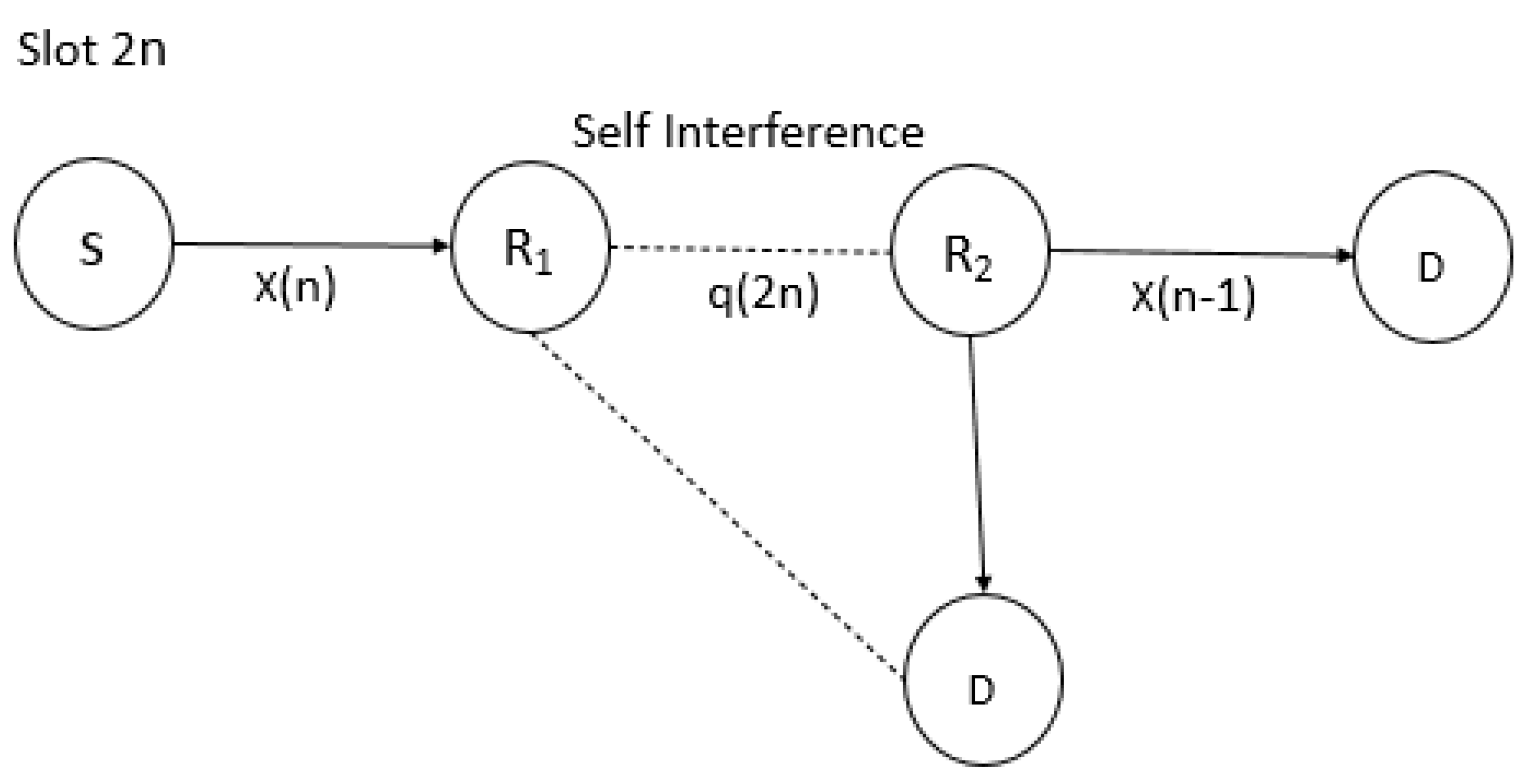
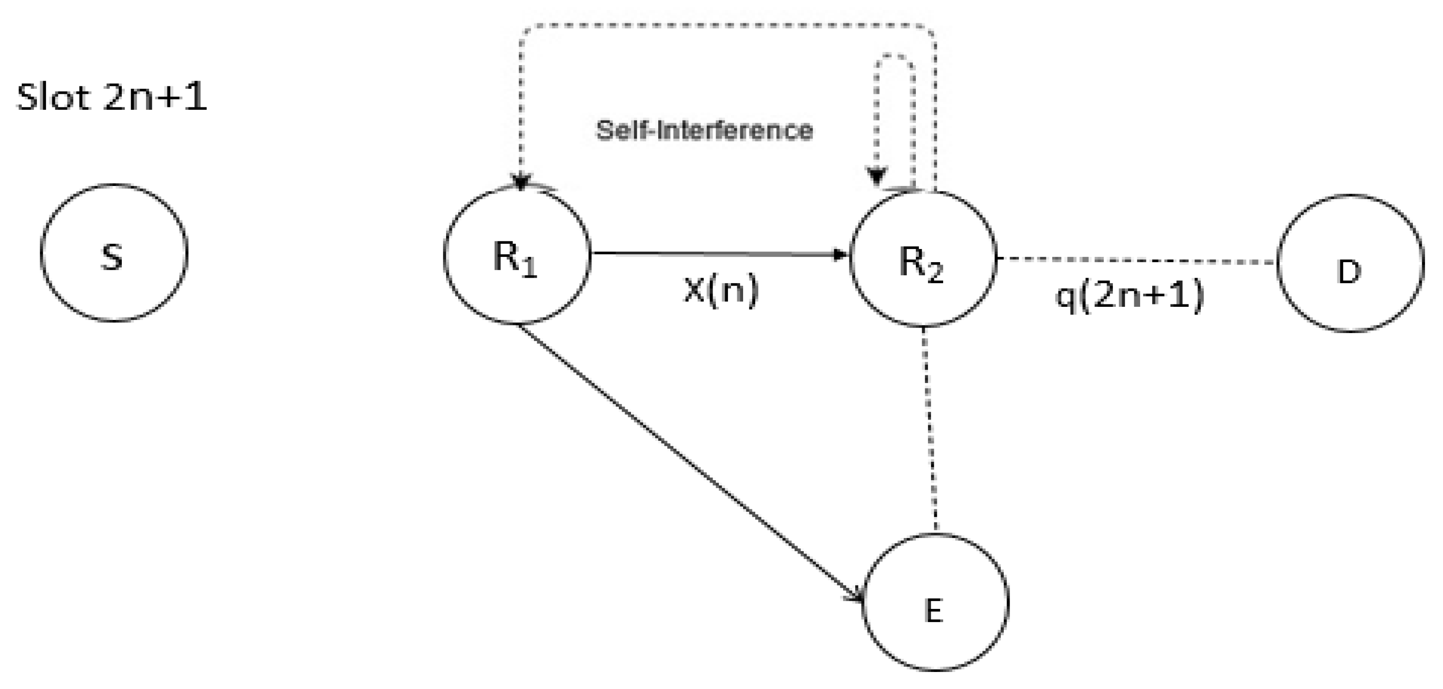
2.2. Full Duplex Decode and Forward (DF) Relay Scheme

This section involves work performed in a pair of steps. The Full-Duplex Relay transmits the jamming signal when it receives the required signal from the preceding node. The first occurrence of this is illustrated in Figure 3. We assumed that the FDR Self-Interference Signal (SIC) is canceled completely in the first time slot. In the next time slot, at the 2nth time slot, S sends a jamming signal x(n) to R1, R2 sends the previous x(n − 1) to the D 2nth time slot, and E obtains the jamming signal through the R1 and R2 data signals. As such, the received signals derived at R1, E and D are expressed as:
    y R 1 ( 2 n ) = ρ P s h S R 1 * x ( n ) + n R 1 ( 2 n )
y E ( 2 n ) = ρ P R 2 h R 2 E * x ( n ) + ρ P R 1 J h R 1 E * q ( 2 n ) + n E ( 2 n )
y D ( 2 n ) = ρ P R 2 h R 2 D * x ( n 1 ) + n D ( 2 n )
where x(n) represents the carried data symbol with the Unit Power, denoted as P s and P R 2 which are the transmitting powers of source S and relay R 2   ;   q ( 2 n ) is the unit power of the jamming signal, and P R 1 J   is the relay R 1 of the jamming signal. In addition,   n R 1 ( 2 n ) , n D ( 2 n ) and n E ( 2 n ) , corresponding to R 1 , D, and E, respectively, represent the additive white Gaussian noise (AWGN).   ρ is the ratio of the Energy Harvesting power splitting technique.
Figure 3. Transmission of signals in 2nth time slot.
In the second phase, according to Figure 3, the x(n) signal from the source is sent and received by the destination. The secrecy is calculated according to the graph. We suspect that in the next time slot, R1 effectively decodes the signal x(n) and transmits re-encoded signals. The (2n + 1)th receiving the signal at R2 and E in the time slot is obtained as follows:
y R 2 ( 2 n + 1 ) = ( 1 ρ ) P R 1 h R 1 R 2 J * x ( n ) + n R 2 ( 2 n + 1 )
y E ( 2 n + 1 ) = ( 1 ρ ) P R 1 h R 1 E * x ( n ) + ( 1 ρ ) P R 2 J h R 2 E * q x ( 2 n + 1 ) + n E ( 2 n + 1 )
where   P R 2 J   signifies the jamming signal power of R 2 and P R 1 is the transmitted power of R 1 . Here, eavesdropper E performs maximum ratio combining (MRC) to decode x(n), with   y E ( 2 n + 1 ) and   y E ( 2 n + 2 ) . This is shown in Figure 4 and Figure 5.
Figure 4. Transmission of signals in the 2(n + 1)th time slot.
Figure 5. Signal transmission in the 2(n+2)th time slot.

2.3. Amplify and Forward (AF) Relaying Scheme

This involves two phases: the first phase is the same as the DF scheme as demonstrated in Figure 3; in the 2nth time slot, the R1, R2, and E signals are received, and the relevant equations are represented by (5)–(7). In the next time slot, the relay sends the amplified signals to the destination using the Amplify and Forward Scheme and by jamming the signal source to the eavesdropper. Therefore, in the (2n + 1)th time slot, the signal received R2 and E as follows:
y R 2 ( 2 n + 1 ) = G ( 1 ρ ) P R 1 h R 1 R 2 * x ( n ) + n R 2 ( 2 n + 1 )
y E ( 2 n + 1 ) = G ( 1 ρ ) P R 1 h R 1 E * x ( n ) + ( 1 ρ ) P R 2 J h R 2 E * q ( 2 n + 1 ) + n E ( 2 n + 1 )
whereas the scaling factor [11] is assessed by G = 1 P R 1 | h S R 1 | 2 + N o and the noise variance is indicated by the N o .

3. Achievable Secrecy Rate

3.1. DF Scheme

In (5)–(9), the Secrecy Rate values at D and E are given [11]:
R d = 1 2 l o g 2 ( 1 + ρ P R 2 α R 2 D )
R e = 1 2 l o g 2 ( 1 + ( 1 ρ ) P R 1 α R 1 E 1 + P R 2 J α R 2 E + ( 1 ρ ) P R 2 α R 2 E 1 + P R 1 J α R 1 E )
where, α R 2 D = | h R 2 D | 2 σ 2 , α R 1 E = | h R 1 E | 2 σ 2 and α R 2 E = | h R 2 E | 2 σ 2 .
It is possible to use secrecy rate obtained in Equations (12) and (13) and the achievable Secrecy Rate can be represented as Rs = max {RdRe, 0}:
R d R e = 1 2 l o g 2 [ 1 + ρ P R 2 α R 2 D 1 + ( 1 ρ ) P R 1 α R 1 E 1 + P R 2 J α R 2 E + ( 1 ρ ) P R 2 α R 2 E 1 + P R 1 J α R 1 E ]

3.2. AF Scheme

In (10) and (11), the Secrecy Rate values at D and E are given [11]:
R d = 1 2 l o g 2 ( 1 + G 2 ρ P R 2 α R 2 D )
R e = 1 2 l o g 2 ( 1 + ( 1 ρ ) P R 1 α R 1 E 1 + P R 2 J α R 2 E + G 2 ( 1 ρ ) P R 2 α R 2 E 1 + P R 1 J α R 1 E
The secrecy rate is obtained in Equations (15) and (16) as Rs = max {RdRe, 0}, whereas
R d R e = 1 2 l o g 2 [ 1 + G 2 ρ P R 2 α R 2 D 1 + ( 1 ρ ) P R 1 α R 1 E 1 + P R 2 J α R 2 E + G 2 ( 1 ρ ) P R 2 α R 2 E 1 + P R 1 J α R 1 E ]

4. Analysis of Outage Probability

Here, the analytical expressions of the OP for the Energy-Harvesting system performance in the AF and DF Schemes are derived. In addition, the exact accurate Secrecy Outage Probability (SOP) is expressed in a one-integral format and the closed-format asymptotic (CFA) is used for higher averaged SNRs. Throughout the work, the secrecy event usually happens when the achievable secrecy capacity of Rs is below the secrecy capacity of the target Rt, as follows:
𝑃out (Rt) = Pr [Rs < Rt]
where Rt = 22Rt−1 and Rt denote the data rate of the target, and the probability of event A is Pr (A).

4.1. Decode and Forward Scheme

The DF Relaying Scheme’s Outage Probability (OP) can be calculated as:
P o u t D F ( R t ) = ( max { R s , max min { R d R e } < R t } )
The complete proof of Equation (19) given in Appendix A.
Theorem 1.
A methodological formulation can be given for the DF relaying scheme (OP).
P o u t D F ( R t ) = m = 1 M m k = 1 K [ 1 λ R e k μ e y λ R e k R t λ R k d m β y d y ]
where A D F S c h e m e = μ e y λ R e k R t λ R k d m β y d y .
To the best of the authors’ knowledge, the integral A D F S c h e m e in Equation (20) cannot be condensed. The below lemma based on the Maclaurin series allows the generation of a tractable format from the result shown in Theorem 1.
Lemma 1.
For θ , ξ > 0 ,   integral A μ e θ x ξ x dx   could be presented as
A e μ θ θ ξ   Γ ( 0 , μ θ ) + u = 2 ( 1 ) u   ξ u u ! × [ e μ θ v = 1 u 1 ( v 1 ) ! ( θ ) u v 1 ( u 1 ) ! μ v ( θ ) u 1 ( u 1 ) ! E i ( μ θ ) ]
where   Γ (   ,   ) is the Gamma function of upper incomplete, E i (   ) is an exponential type of integral function.
Proof. 
Using the Maclaurin series of the term   e ξ x = u = 1 ( 1 ) u   ξ u u ! x u and after some algebraic analysis, the solution can be obtained using Formula (21).
Applying Lemma 1, an approximate closed-form expression for the DF Scheme, using the DF relaying operation, can be obtained as:
P o u t , a p p r o x D F = m = 1 M m k = 1 K [ 1 θ 1 [ e μ θ θ ξ   Γ ( 0 , μ θ ) + u = 2 ( 1 ) u   ξ u u ! [ e μ θ v = 1 u 1 ( v 1 ) ! ( θ ) u v 1 ( u 1 ) ! μ v ( θ ) u 1 ( u 1 ) ! E i ( μ θ ) ] ] ]
where   θ 1 = λ R e k and ξ 1 = γ t h λ R k d m β . □

4.2. AF Strategy for Relaying

From Equations (10)–(20), assuming AF relaying, the AF Scheme’s OP can be provided by
P o u t A F ( R t ) = ( max { R s , max { R d R e } < R t } )
The complete proof of Equation (23) given in Appendix B.
Theorem 2.
A methodological formulation for AF Scheme OP utilizing AF relays may be derived as:
P o u t A F ( R t ) = m = 1 M m k = 1 K [ 1 λ R e k × μ e y λ R e k α R t y + ( R t ) λ R k d m ( α y R t ) β y d y ]  
where     Ψ A F S c h e m e = μ e y λ R e k α R t y + ( R t ) λ R k d m ( α y R t ) β y d y .
It should be noted that the integral of   Ψ A F S c h e m e in Equation (24) does not have an expression in a closed-form. Here, for two real non-negative numbers, it is possible to obtain b a b a + b + 1 a b a + b when a and b are large enough. The end of the SNR R e A F in (16) can therefore be computed by:
R e A F R 1 E R 2 E R 1 E + R 2 E = max 1 k K R 1 E R 2 E R 1 E + R 2 E  
Plugging (25) into (23) and then performing the steps set out in Appendix B, the integration of the Ψ A F S c h e m e in (24) can be computed by.
Ψ A F S c h e m e μ e y λ R e k α R t λ R k d m ( α y R t ) β y d y                              

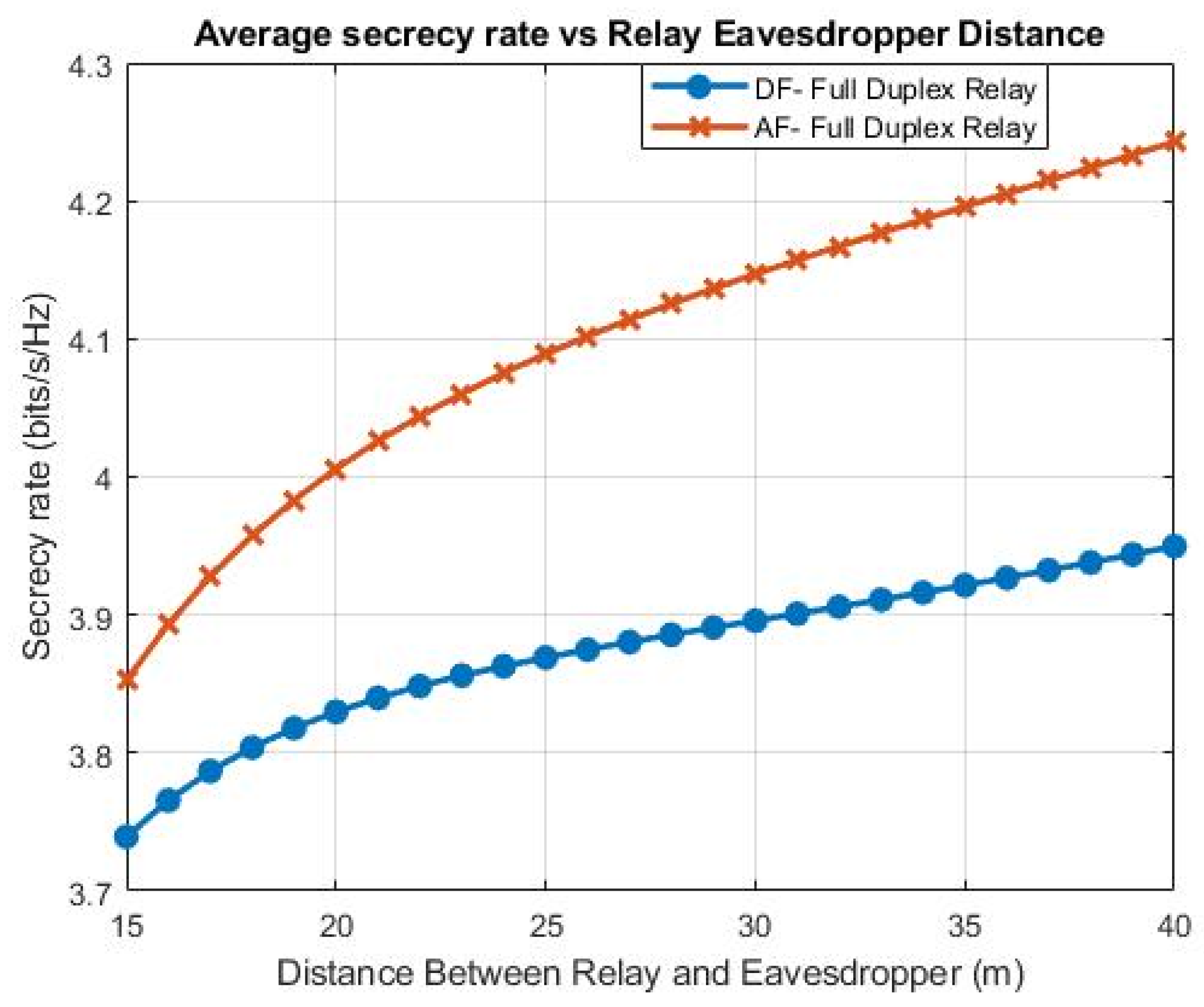
5. Numerical Evaluation and Results

This section describes the investigated secrecy performance of the designed system utilizing (EH) for both the DF and AF full-duplex Cooperative Schemes, as illustrated in Figure 6. The source (S), the relays (R1 and R2) and the destination (D) are considered in a line [2]. Here, dSR1, dR1R2, dR2D, dR1E and dR2E represent the distance between the Source and Relay1, Relay1 and Relay2, Relay2 and the Destination, Relay1 and the Eavesdropper, and Relay2 and the Eavesdropper, respectively. Moreover, the distance between jamming relay R1 and Eavesdropper E is calculated as:
d R 1 E = d R 1 E 2 + d R 2 E 2  
Figure 6. Illustration of PS EH Simulation.
Sight (LOS) channel model uses “d − c/2ejθ” and is followed by channels between any two nodes, whereas d is the space between nodes and θ, which is uniformly distributed in a random phase in the [0, 2π] range, and the path loss exponent c = 3.50. The assumption is that P_B = 30 dBm and the noise power or variance ( N o ) = −40 dBm, d_BR1 = d_BR2 = 7 m,   α = 0.99 η = 0.9 and ρ = 0.5 .
In Figure 7 and Figure 8, a graph is plotted for the Secrecy Rate and the distance between Relay2 (R2) and the Destination (D), with the AF and DF strategies, when dR1R2 = 10 m, dR2E = 15 m. The graph shows the decreasing Secrecy Rate with the increasing of the distance between Relay2 and the Destination (D), but at the same time, due to power splitting receiver in the Energy Harvesting (EH) system, the Secrecy Rate in the DF Scheme becomes 7, and becomes 7.5 in the AF Scheme, which is considered good. In addition, from Figure 7 and Figure 8, it can be seen that AF Scheme gives a better Secrecy Rate than the DF Scheme.
Figure 7. Secrecy Rate vs. dR2D for the EH System.
Figure 8. Secrecy Rate vs. dR2D for the proposed EH PS System.
In Figure 9 and Figure 10, graphs are plotted for the Secrecy Rate and the distance between Relay2 (R2) and the Eavesdropper (E) with the AF and DF Strategies, when dR1R2 = 10 m and dR2D = 15 m. The graph shows that the Secrecy Rate increases with the increasing of the distance between (R2) and (E) in the Energy-Harvesting System. The highest value of the Secrecy Rate in the Energy Harvesting (EH) System with AF Scheme is 4.23, and with the DF Scheme, this value is 3.95. In the proposed Energy Harvesting Power Splitting System, the Secrecy Rate is better in both the schemes because of the Power Splitting Receiver, and the values of Secrecy rate become 5.08 with the AF Scheme and 4.42 with the DF Scheme. Therefore, to increase the Secrecy Rate, it is important to use a share of the useful power to relay the jamming signals when applying both the AF and DF Strategies.
Figure 9. Secrecy Rate vs. dR2E for the EH System.
Figure 10. Secrecy Rate vs. dR2E for the EH PS System.
In Figure 11 and Figure 12, graphs are plotted for the Secrecy Rate and the path loss exponent factor with both AF and DF Strategies, when dR1R2 = 10 m, dR2D = 15 m and dR2E = 15 m. Path loss plays a vital role in the calculation of the Secrecy Rate. The graph shows that as the path loss exponent is increased from 2 to 4, the Secrecy Rate decreases gradually, in both EH systems, from 6.5 to 2.9, and in the proposed EH PS system, it decreases from 7.6 to 3.6. This shows that the increment in the path loss exponent degrades the system Secrecy Rate in both the AF and DF Schemes, implying that the self-interference between the relays should be minimized so that the Secrecy Rate does not decrease with the increase in path loss exponent factor.
Figure 11. Secrecy Rate vs. Path Loss Exponent for the EH System.
Figure 12. Secrecy Rate vs. Path Loss Exponent.
In Figure 13, a graph is plotted depicting the Outage Probability vs the transmitted SNR with the power splitting ratio ρ = 0.5 for the AF and DF Schemes using exact, approximate and asymptotic results. According to our Proposed System Model, the number of destinations (D) is 1 and the number of relays is 2. The curve behavior is similar to a trending curve as the splitting ratio is the same for the DF and AF schemes. In our proposed work, the SNR limit is −10 to 20 dBm, but as the SNR limit increases, the Outage Probability becomes better because the higher SNR value indicates that the Signal power is larger than the Noise power. From the results, it can be clearly seen that from SNR −10 to 15 dBm, DF-approx. and AF-approx. give better Outage Probability values than DF-exact and AF-exact. In addition, in all three scenarios, DF-asymptotic and AF-asymptotic give the highest Outage Probabilities as compared to the other four scenarios.
Figure 13. Outage Probability vs. SNR.
In Figure 14, a graph is plotted depicting the Outage Probability and transmitted SNR for different relays with ρ = 0.5 , for both the AF and DF Schemes, using the exact solution. Generally, the outage Pout (Rt) at end-to-end SNR falls under a few threshold values. When the destination and relay are both 1, then the slope of the curve is almost the same for the AF Scheme and the DF Scheme, but when the destination is 1 and relay is 2, then the slope varies for both the AF and DF Schemes. This shows that as the number of Relays grows, the graph shows increased diversity. Table 2 shows a comparison of the proposed work with the published literature.
Figure 14. Outage Probability vs. SNR at different K values.
Table 2. Comparison table.

6. Conclusions

In this paper, we investigated a three-hop relay network system model, in which the source and relay obtained energy by means of the power beacon with the help of a time-switching EH Scheme. The system’s Secrecy Rate considers two cooperative relay schemes: DF and AF. The new techniques use EH, while PS guarantees greater energy efficiency and confidentiality values relative to the conventional EH process. Through the use of the Power Splitting Scheme, the Secrecy Rate is improved by 50.5% in the AF Scheme and by 44.2% in the DF Scheme between the eavesdropper and the relay, which, in the proposed system (Energy Harvesting), are 40 m apart. The resulting analysis shows that the system with PS and EH allows a higher Secrecy Rate than the Conventional EH System in the AF Cooperative Communication Scheme but not in the DF Scheme. It is shown from the system model that when the channel’s path loss exponent increases, the transmission of the information becomes less secure because of self-interference (SIC) between the relays. The compressed sensing multi-hop DF and AF relaying scheme in Energy Harvesting will require further attention in the future.

Author Contributions

Conceptualization, N.S., S.Y., E.M.A., M.A.K., R.S.A.L. and M.A.; methodology, N.S., S.Y., I.B., M.M.K. and M.A.; software, I.B., S.Y., R.S.A.L. and M.A.K.; validation, N.S., S.Y., E.M.A., R.S.A.L., M.A.K., M.M.K., S.K., M.A. and E.L.; formal analysis, S.Y., M.A.K., R.S.A.L., I.B., M.M.K. and M.A.; investigation, N.S., S.Y., E.M.A., R.S.A.L., M.M.K. and M.A.; resources, N.S., S.Y., E.M.A., M.A.K., R.S.A.L., M.M.K., S.K., M.A. and E.L.; data curation, N.S., S.Y., M.A.K., R.S.A.L., I.B. and M.M.K.; writing—original draft preparation, N.S.; writing—review and editing, N.S., S.Y., E.M.A., M.A.K., R.S.A.L., I.B., M.M.K., S.K., M.A. and E.L.; visualization, N.S., S.Y., E.M.A., R.S.A.L., M.M.K., M.A. and E.L.; supervision, S.Y.; project administration, S.Y., M.A. and E.L.; funding acquisition, S.Y., E.M.A., S.K., M.A. and E.L. All authors have read and agreed to the published version of the manuscript.

Funding

This work is supported by the Science and Technology Innovation Project of Zhengzhou 2019CXZX0037, the Special Project for Inter-Government Collaboration of State Key Research and Development Program 2016YFE0118400, and NSFC U1604159. In addition, this project has received funding from the Universidad Carlos III de Madrid and the European Union’s Horizon 2020 research and innovation program under the Marie Sklodowska-Curie Grant 801538. Furthermore, it received partial funding from the Researchers Supporting Project number RSP-2021/58, King Saud University, Riyadh, Saudi Arabia.

Data Availability Statement

All data are included within the manuscript.

Acknowledgments

The authors appreciate the financial support from the Science and Technology Innovation Project of Zhengzhou 2019CXZX0037, the Special Project for Inter-Government Collaboration of State Key Research and Development Program 2016YFE0118400, and NSFC U1604159. Furthermore, the funding from the Universidad Carlos III de Madrid and the European Union’s Horizon 2020 research and innovation program under the Marie Sklodowska-Curie Grant 801538 is appreciated. Additionally, the partially supported from the Researchers Supporting Project number (RSP-2021/58), King Saud University, Riyadh, Saudi Arabia, is acknowledged.

Conflicts of Interest

The authors declare no conflict of interest.

Nomenclature

AcronymDefinition
AFAmplify-and-Forward
DFDecode-and-Forward
α Time-Switching Factor
FDRFull Duplex Relay
DNDestination Node
RNRelay Network
SNSource Node
TTransmission Period
ρ rPower Harvest at Relay
R e Relay Eavesdropper
ξ Radio Frequency Energy Harvesting
SWIPTSimultaneous Wireless Information and Power Transmission
TSRTime-Switching Relay-Oriented Protocol
PSRPower-Splitting-Oriented Relay Protocol
AWGNAdditive White Gaussian Noise
PLSPhysical Layer Security
RFRadiofrequency
RNRelay Node
P B Power Beacon
R d Relay Destination
D R 1 R 2 Distance Between Relay1 and Relay2
ρ Power
η Energy Conversion efficiency
N o   Noise power or variance
P J   Jamming Signal of power
R e A F Relay Eavesdropper AF

Appendix A

The complete Outage probability Theorem 1 given proof Equation (19) can be expressed as:
P o u t D F ( R t ) = P r ( R s b < R t ) m = 1 M P r ( D b = D m ) × k = 1 K P r ( min { α | h R k E | 2 β | h R k E | 2 | h R k D m | 2 } < R t )
The reader can easily understand by Lemma 1 P r ( R s b < R t ) .
Lemma 2.
Let | h b | 2   max 1 l L { | h l | 2 } , l { 1 , 2 , . L } , where | h b | 2 { | h R b D | 2 , | h R b E | 2 } , | h l | 2 { | h R m D | 2 , | h R m E | 2 } , L { M , K } .
The cumulative division function (CDF), F | h b | 2 ( z ) , and the Outage probability compactness function (PDF), F | h b | 2 ( z ) , of | h b | 2 can be expressed as follows:
F | h b | 2 ( z ) = 1 + l = 1 L ( 1 ) l q 1 = 1 L q l = 1 L e z t = 1 l λ q t
q 1 < < q l
F | h b | 2 ( z ) = l = 1 L ( 1 ) l + 1 q 1 = 1 L q l = 1 L ( t = 1 l λ q t ) e z t = 1 l λ q t
q 1 < < q l
Proof. 
Since | h l | 2 s are random variables that are independent of one another and the CDF of | h b | 2 can be shown by   F | h b | 2 ( z ) = l = 1 L P r ( | h l | 2 < z ) , using the following the multinomial expansion identity
l = 1 L ( 1 x 1 ) = l = 0 L ( 1 ) l q 1 = 1 L q l L t = 1 l x q t
q 1 < < q l
and a few subsequent algebraic steps, F | h b | 2 can be obtained via (A1). Taking the derivative of the right-hand side of (A1), the PDF of | h b | 2 can be obtained using Equation (A2). The complete proof of Lemma 2 is given below. Invoking Lemma 2, the probability P r ( R s b < R t ) can be given by
Ω = 1 + l = 1 M ( 1 ) l q 1 M q l M e R t γ t = 1 l λ R s q t
Next, m in Equation (A1) part is derived in the following lemma. □
Lemma 3.
Let m P r ( d b = d m ) and Γ k P r ( R b = R k ) . m and Γ k , respectively, given as follows:
m = 1 + l = 1 l m M ( 1 ) l q 1 = 1 , m M q l = 1 , m M λ R s m λ R s m + t = 1 l λ R s q t
q 1 < < q l
Γ k = 1 + l = 1 l k K ( 1 ) l q 1 = 1 , k K q l = 1 , k K λ R k E λ R k E + t = 1 l λ R q t E
q 1 < < q l
Proof. 
Obtaining the multinomial expansion identity is (A3)–(A6) is straightforward using a similar technique. The proof for Lemma 3 is now completed.
The remaining equation part of (A1) will be worked on in the following manner. If Y | h R k E | 2 and it is specified that Y = y, A can be given as:
A = 0 [ 1 P r ( α y R t ) P r ( β y | h R k D m | 2 R t ) ] f Y ( y ) d y
where f Y ( y ) shows the PDF value of Y. Since Y = | h R e | 2 and | h R k D m | 2 follow exponential division with the rate parameters λ R k E and λ R k D m , respectively, A can be obtained as:
A = 1 λ R k E μ e y λ R k E R t λ R k D m β y .
By plugging (A7) and (A4) into Equation (A1), and invoking Lemma 3, Equation (20) can be used to obtain. □

Appendix B

The complete AF Relying Scheme Theorem 2 is given by Outage Probability, P o u t A F ( R t ) in Equation (23) can be expressed as
P o u t A F ( R t ) = P r ( R s b < R t < R t ) m = 1 M P r ( D b = D m ) × k = 1 K P r ( α | h R k E | 2 β | h R k E | 2 | h R k D m | 2 α | h R k E | 2 + β | h R k E | 2 | h R k D m | 2 + 1 ) < R t
Next, conditioning on | h R k E | 2 = x ,  B in the (A8) can be shown as follows:
B = 0 [ P r ( ( α x R t ) β y | h R k D m | 2 < α R t x + R t ] f | h R k E | 2 ( x ) d x
if x [ 0 , R t α ] , the probability in Equation (A9) is always 1. Thus, (A9) can be shown as follows:
B = 0 μ f X ( x ) d x + μ P r ( | h R k D m | 2 < α R t x + R t ( α x R t ) β x ) f X ( x ) d x
where   μ = R t α . Since | h R k E | 2 and | h R k D m | 2 follow the exponential divisions with rate parameters λ R k E and λ R k D m , respectively, and after the manipulation of algebraic steps, B can be shown as follows:
              B = 1 λ R k E μ e y λ R k E ( α R t y + R t ) λ R k D m ( α y R t ) β y d y
Plugging (A4), (A5) and (A11) into (A8), Equation (24) can be given. This is the complete Theorem 2 proof.

References

  1. Li, X.; Zheng, Y.; Khan, W.U.; Zeng, M.; Li, D.; Ragesh, G.K.; Li, L. Physical layer security of cognitive ambient backscatter communications for green Internet-of-Things. IEEE Trans. Green Commun. Netw. 2021, 5, 1066–1076. [Google Scholar] [CrossRef]
  2. Waqar, O.; Tabassum, H.; Adve, R.S. Secure beamforming and ergodic secrecy rate analysis for amplify-and-forward relay networks with wireless powered jammer. IEEE Trans. Veh. Technol. 2021, 70, 3908–3913. [Google Scholar] [CrossRef]
  3. Nawaz, M.; Khan, W.U.; Ali, Z.; Ihsan, A.; Waqar, O.; Sidhu, G.A.S. Resource Optimization Framework for Physical Layer Security of Dual-Hop Multi-Carrier Decode and Forward Relay Networks. IEEE Open J. Antennas Propag. 2021, 2, 634–645. [Google Scholar] [CrossRef]
  4. Shim, Y.; Park, H.; Shin, W. Joint time allocation for wireless energy harvesting decode-and-forward relay-based IoT networks with rechargeable and nonrechargeable batteries. IEEE Internet Things J. 2020, 8, 2792–2801. [Google Scholar] [CrossRef]
  5. Nguyen, T.N.; Tran, P.T.; Voznak, M. Wireless energy harvesting meets receiver diversity: A successful approach for two-way half-duplex relay networks over block Rayleigh fading channel. Comput. Netw. 2020, 172, 107176. [Google Scholar] [CrossRef]
  6. Atapattu, S.; Ross, N.; Jing, Y.; He, Y.; Evans, J.S. Physical layer security in full-duplex multi-hop multi-user wireless network with relay selection. IEEE Trans. Wirel. Commun. 2019, 18, 1216–1232. [Google Scholar] [CrossRef]
  7. Phan, V.-D.; Nguyen, T.N.; Le, A.V.; Voznak, M. A Study of Physical Layer Security in SWIPT-Based Decode-and-Forward Relay Networks with Dynamic Power Splitting. Sensors 2021, 21, 5692. [Google Scholar] [CrossRef] [PubMed]
  8. Chang, S.; Li, J.; Fu, X.; Zhang, L. Energy Harvesting for Physical Layer Security in Cooperative Networks Based on Compressed Sensing. Entropy 2017, 19, 462. [Google Scholar] [CrossRef] [Green Version]
  9. Truong, T.-V.; Vo, N.-V.; Ha, D.-B.; Tran, D.-D. Secrecy performance analysis of energy harvesting wireless networks with multiple power transfer stations and destinations in the presence of multiple eavesdroppers. In Proceedings of the 2016 3rd National Foundation for Science and Technology Development Conference on Information and Computer Science (NICS), Danang, Vietnam, 14–16 September 2016; pp. 107–112. [Google Scholar] [CrossRef]
  10. Shen, H.; Wang, J.; Levy, B.; Zhao, C. Robust optimization for amplify-and-forward MIMO relaying from a worst-case perspective. IEEE Trans. Signal Process. 2013, 61, 5458–5471. [Google Scholar] [CrossRef] [Green Version]
  11. Gong, S.; Wang, S.; Chen, S.; Xing, C.; Hanzo, L. Robust energy efficiency optimization for amplify-and-forward MIMO relaying systems. IEEE Trans. Wirel. Commun. 2019, 18, 4326–4343. [Google Scholar] [CrossRef] [Green Version]
  12. Jindal, P.; Sinha, R. Physical layer security with energy harvesting in single hop wireless relaying system. In Proceedings of the International Conference on Information Science and Applications, Changsha, China, 21–23 July 2017; Springer: Singapore, 2017; pp. 249–256. [Google Scholar]
  13. Sinha, R.; Jindal, P. A study of physical layer security with energy harvesting in single hop relaying environment. In Proceedings of the 2017 4th International Conference on Signal Processing and Integrated Networks (SPIN), Noida, India, 2–3 February 2017; pp. 530–533. [Google Scholar] [CrossRef]
  14. Pal, S.; Jindal, P. Secrecy Performance Analysis for Multi-hop and Single-Hop Relaying Model. Opt. Wirel. Technol. Proc. OWT 2019 2020, 648, 437. [Google Scholar]
  15. Gawtham, K.D.; Jindal, P. Analysis of amplify and forward technique to improve secrecy rate in multi-hop relaying system. In Proceedings of the 2016 IEEE International Conference on Recent Trends in Electronics, Information & Communication Technology (RTEICT), Bangalore, India, 20–21 May 2016; pp. 62–64. [Google Scholar]
  16. Zhou, N.; Wan, B.; Gong, L. Secrecy rate maximisation for non-linear energy harvesting relay networks with cooperative jamming and imperfect channel state information. ET Commun. 2020, 14, 923–929. [Google Scholar] [CrossRef]
  17. Ding, H.; Ge, J.; da Costa, D.B.; Jiang, Z. A new efficient lowcomplexity scheme for multi-source multi-relay cooperative networks. IEEE Trans. Veh. Technol. 2011, 60, 716–722. [Google Scholar] [CrossRef]
Publisher’s Note: MDPI stays neutral with regard to jurisdictional claims in published maps and institutional affiliations.

Article Metrics

Citations

Article Access Statistics

Multiple requests from the same IP address are counted as one view.