Article

On the Optimal Selection of Flux Barrier Reconfiguration for a Five-Phase Permanent Magnet Assisted Synchronous Reluctance Machine for Low-Torque Ripple Application

by
Hamidreza Ghorbani
1,
Mohammadreza Moradian
1,2,* and
Mohamed Benbouzid
3,*
1
Department of Electrical Engineering, Najafabad Branch, Islamic Azad University, Najafabad P.O. Box 8514143131, Iran
2
Smart Microgrid Research Center, Najafabad Branch, Islamic Azad University, Najafabad P.O. Box 8514143131, Iran
3
Institut de Recherche Dupuy de Lôme (UMR CNRS 6027), University of Brest, 29238 Brest, France
*
Authors to whom correspondence should be addressed.
Electronics 2022, 11(1), 41; https://doi.org/10.3390/electronics11010041
Submission received: 18 November 2021 / Revised: 12 December 2021 / Accepted: 17 December 2021 / Published: 23 December 2021
(This article belongs to the Special Issue Robust Design Optimization of Electrical Machines and Devices)

Abstract

:
This paper aims to investigate the reconfigurations of rotor flux barriers for a five-phase Permanent Magnet Assisted Synchronous Reluctance Machine (PMASynRM). To precisely study the performance of the proposed configurations, a conventional PMASynRM with double-layer flux barriers is included in the study. Since the novel rotor schemes consume the same amount of rare-earth magnets, steel sheet materials, and copper wire, resulting in no extra manufacturing costs, the optimal reconfiguration should be determined, providing developed electromagnetic characteristics. Thus, all the proposed models are designed and analyzed under the same condition. The Lumped Parameter Model (LPM) is exported to the Finite Element Method (FEM) for precise analysis to reach developed torque and lower values of torque ripple. Based on the FEM results the model presenting the lowest torque fluctuations is selected as the optimal model and dynamically investigated. According to the results, in comparison with the conventional model, the introduced rotor designs provide a much lower value of torque fluctuations with a desirable amount of electromagnetic torque and power. In addition, the optimal model presents high values of power factor and efficiency, making it a vital alternative for low-torque ripple high-speed operations with no extra cost to the implementation process.

1. Introduction

Electric Synchronous Motors (SyncM) are widely used in industrial applications due to their electromagnetic characteristics such as robustness [1], noticeable torque/power density [2,3], and efficient performance [3,4,5,6]. These types of electric motor can be categorized into (i) surface mounted Permanent Magnet Synchronous Motor (SPMSM), (ii) Interior Mounted Permanent Magnet Synchronous Motor (IPMSM), (iii) Permanent Magnet Assisted Synchronous Reluctance Motor (PMASynRM) [6]. Among these types of PMSM, the PMASynRM has attracted a huge number of investigators to study the characteristics [6,7,8,9], apply optimization processes [10,11,12,13], and perform enhancement for different applications such as electric vehicular systems [4,14,15,16]. Therefore, a large number of studies are devoted to introducing new branches of structural design for PMSM [4,15,17,18,19,20,21,22]. A novel dual rotor PMASynRM is introduced in [4] in which toroidal winding is applied to fully utilize electromagnetic torque (PM torque and reluctance torque). Based on the results of the Finite Element Method (FEM), the proposed configuration presents robustness through irreversible demagnetization. Wang et al., presented a new SynRM composed of grain-oriented and non-oriented silicon steels [17]. Accordingly, employing a reasonable rotor design, the results demonstrate torque improvement and significant torque ripple reduction. Liu et al., presented a novel modular PMASynRM structure that is composed of two axially combined rotor modules [18]. According to detailed reported analysis results, the new proposed motor structure provides higher values of power factor along with lower torque ripple and eddy current losses compared with conventionally known IPM and PMASynRM structures. A new hybrid PMASynRM with sandwiched magnets is investigated by Zhao et al., to study torque, efficiency, power factor, and torque ripple enhancements [19]. Applying FEM to the proposed design, the results exhibit highly improved torque density, power factor, and efficiency along with a great decline in value of torque ripple. Cai et al., reviewed recent research on electric powertrains for new electric vehicles [20]. Based on the results, this study presents efficiency, speed, size, reliability, control simplicity, and performance comparison for Direct Current (DC) motor, Induction Motor (IM), PMSM, so that it is found that although the PMSM requires a complicated control system, it presents best electromagnetic performance, high efficiency, and more reliability. Cui et al., presented a novel PMSM with an optimized air-gap for a high-power electric motorcycle. The results show improvements in torque and efficiency by asymmetric structural design optimization providing a wide range of speed and performance control. Tawfiq et al., in [23] present the investigation of a 3-phase SyncRM while transferring the machine to a 5-phase SyncRM. It has been obtained after optimization and investigating of the proposed 5-phase SyncRM that in an increasing rate of the rotor speed, the produced torque and efficiency increased significantly up to 33% and 3.5% respectively, in comparison with the 3-phase structure. In addition, in terms of one-phase faulty situation the 5-phase model works at 98.84% of it 3-phase machine’s electromagnetic torque while the 3-phase model only works at about 45% of its rated torque with a high torque ripple value of 228%. Thus, a 5-phase SyncRM not only provides better torque and efficiency performance particularly in sensitive applications such as military and propulsion systems, it also brings about higher reliability under faulty situations.
Although a three-phase system is widely applied to electrical machines, due to developments of power electronics devices, the necessity of having a limited number of phases dismissed and multiphase drive systems can be applied to supply and control electrical machines. A five-phase system can be used as the drive system in PMASynRM, which brings advantages as (i) higher torque, (ii) higher efficiency, (iii) reduction of DC-Link harmonics, and (iv) reliability [23,24,25,26,27,28,29]. Moreover, it has been investigated in [8] that while the 3-phase inverter fed Multiphase SynRM would not utilize the full capacity of kVA of the inverter, the multiphase system would provide higher usage of the inverter power. Hence, the multiphase SyncRMs bring about higher torque density and efficiency along with lower values of financial issues. Because the utilization of a multiphase system provides investigators with the elimination of high price PM materials along with lower expenditure on lower price/kVA for inverter technology. Hence, along with better performance, multiphase SyncRMs are a vital alternative particularly for financially sensitive applications such as electric vehicle technologies and home appliances.
As the cost of the rare-earth magnets and steel sheet vary, this paper aims to study novel reconfigurations of rotor flux barriers in a five-phase permanent magnet assisted synchronous reluctance motor that consumes the same volume of steel and PMs compared with a conventional PMASynRM. Due to changes that are made in the FB arc direction, concerning the mathematical rotor design criteria, the chance of local saturation in the iron rib, flux islands, and the corresponding losses can be reduced. Consequently, it results in higher efficiency and power factor, as well as lower torque fluctuations. To aim the torque/power enhancements for the introduced schemes, the Lumped Parameter Model (LPM) of the models are utilized in a 2D Finite Element Analysis (FEA). The models are initially investigated using the corresponding LPM; then, by consideration of the stator current and the current phase angle as the optimization variables, the torque performance is calculated to result in hundreds of operational data points. Afterward, the optimal model, presenting developed torque with the lowest torque ripple is selected and analyzed dynamically. All models are designed using the same values of design parameters and analyzed under the same condition. In Section 2, the structural design data, the calculation methods, and a short mathematical review are presented. The analysis reports are illustrated in Section 3, while Section 4 held some conclusions.

2. Material and Methods

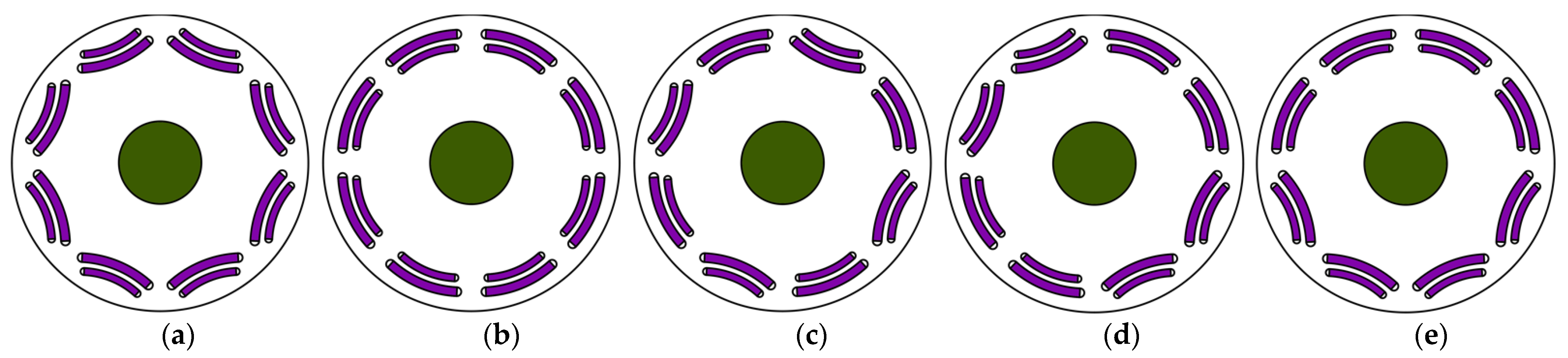
2.1. Proposed Design Scheme

A conventional PMASynRM with novel reconfigurations of rotor flux barriers (FBs) is introduced and investigated in this study. A double-layer FB scheme with inset PMs is considered for all the proposed models. A five-phase full pitch distributed winding is applied to the proposed 40-Slot 8-Pole prototypes (the ratio of the number of stator slots per number of rotor poles per machine phases equals 1). Figure 1, Figure 2 and Figure 3 illustrate the proposed models, structural scheme and winding pattern, and the corresponding winding factor and magneto-motive force (MMF), respectively. According to Figure 1, a conventional double-layer FB PMASynRM (Model-I) is considered in this study in order to compare the performance of the proposed models (Model-II to Model-V) more precisely. The FBs and PMs in the Model-II are reversed in arc direction, the Model-III consists of FBs that are reversed interchangeably one-by-one, and the FBs of the Model-IV interchanged two-by-two and four-by-four in the Model-V. In other words, the Model-III to -V is the combination of the Model-I and -II. The design scheme differentiations, an overview of the system equations, and the conducted numerical methods (as shown in the evaluation procedure in Figure 4) are described in the following subsections. Accordingly, the d-q axes magnetic equivalent circuit (MEC) is evaluated for the LPM and then exported to the FEM to analyze the performance of the machines. Firstly, the steady-state performance at rated speed and nominal stator current is calculated to determine the torque performance and the back electromotive force (Back-EMF). Afterward, the torque enhancement is sensitively analyzed for each model with respect to the stator current amplitude and phase angle variations. Finally, the best-performed model, which produces desirable values of torque density with a lower amount of fluctuations is selected and dynamically studied. To achieve the goal of this paper, the proposed machines are designed and investigated under the same condition using the reported design parameters in Table 1 and the ambient temperature of 40 °C. Thus the proposed schemes consume similar amounts of manufacturing material and require the same steel cutting, resulting in the same value of the machine’s mass and finalized implementation costs, when transforming from the PMASynRM to the Model-V.

2.2. Design Differentiation

The proposed models in this study are designed based on a conventional PMASynRM, shown in Figure 1a. The overall view of the proposed models is similar, whereas the changes that occurred in the flux barrier arc direction caused changes in some design parameters. Figure 5 depicts the major rotor design parameters, in which the Wbk, Wij, and Wrib are the flux barriers, flux islands, and the iron rib width for k = [1,2], j = [1,2] (due to the utilization of two layers of flux barrier, the value of Wi3 is excluded in this study). Transforming the arc face direction from the rotor design of the Model-I to the Model-II made changes in the value of the Wij in which Wi1 > W’i1. Although by applying such transformation the ∑Wij = ∑W’ij, however, the value of the Wrib is not equal to the that of the W’rib, so that in comparison with the Model-II with W’rib = W’i1, the Model-I has Wrib < Wi1. This study is aimed to investigate this transformation by proposing four different configuration models shown in Figure 1. Accordingly, this paper not only investigates the transformed Wrib model (Model-II), but also three models, which are the combination of the Model-I and Model-II are considered for investigation. Based on the design optimization procedures expressed in [17,30], K, the ratio of barrier width to the total rotor width, can be expressed as:
K = k = 1 2 W b k j = 1 k = [ 1 , 2 ] 2 ( W b k + W i j )
In order to maximize torque and minimize torque ripple, the value of K should be limited to 0.5–0.55. Below 0.5, the machine faces a decline in torque production due to heavy magnetic flux leakages and for the greater values of K, due to the saturation of flux islands, the torque fluctuations increase significantly [30]. It has been investigated in [31,32] that the best performance is achievable if the FB island’s width is different in each layer. However, there can be different schemes and reconfigurations that provide the same values for the mentioned criteria in [30,31,32], and such a statement has not been studied before. Hence, five reconfigurations are introduced and analyzed in this study by utilizing the reported parameter values in Table 2, the value of 0.47 and 0.54 are considered for K and K’ respectively, to reduce torque ripple and develop torque performance of the proposed models as it has been addressed in [17,30,31,32]. Moreover, as it has been asserted in [32], two different values are assumed for the Wi1 with one particular Wi2 to achieve better performance.

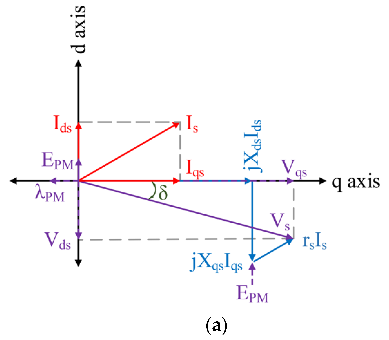
2.3. System Equations Review

The phasor diagram of a PMASynRM with respect to the rotor reference frame is shown in Figure 6a, considering the steady-state condition. Generally, the torque in an m-phase SynRM can be expressed as Equation (2) where Xd, Xq, Ld, Lq, Id, and Iq are the d and q axes reactance, inductance, and currents respectively [28,29].
T e = m 2 N P 2 [ ( L d L q ) I d I q ]
In terms of a PMASynRM, the PM flux linkage (λPM) should be included in Equation (2). Considering a five-phase drive system, the stator phase voltage (Vs) and d-q axes voltages (Vd and Vq respectively) can be defined with the phase resistance, stator current as rs, Is, air-gap flux linkage vector of the stator, the rotor angular speed, permeability of the air as Λs, ωr, μ0, air-gap length and radius, machine stack length as lg, rg, and finally magnetomotive force (MMF) harmonics of the stator and rotor, stator current phase angle as L, fs,h, fr,h, and γd. (See Equations (3)–(8)) [33,34].
V s = r s I s + d Λ s d t = [ v a s v b s v c s v d s v e s ] T
I s = [ I a s I b s I c s I d s I e s ] T
Λ s = [ Λ a s Λ b s Λ c s Λ d s Λ e s ] T
V d = ω r ( L q I q λ P M ) , V q = ω r ( L d I d )
T e = 5 2 N P 2 [ λ P M I d + ( L d L q ) I d I q ]
T r i p p l e = N P 2 μ 0 l g r g L π h = 6 n 1 n = 1 , 2 , 3 , ( h f s , h f r , h sin ( ( h ± 1 ) ω c t ± γ d ) )

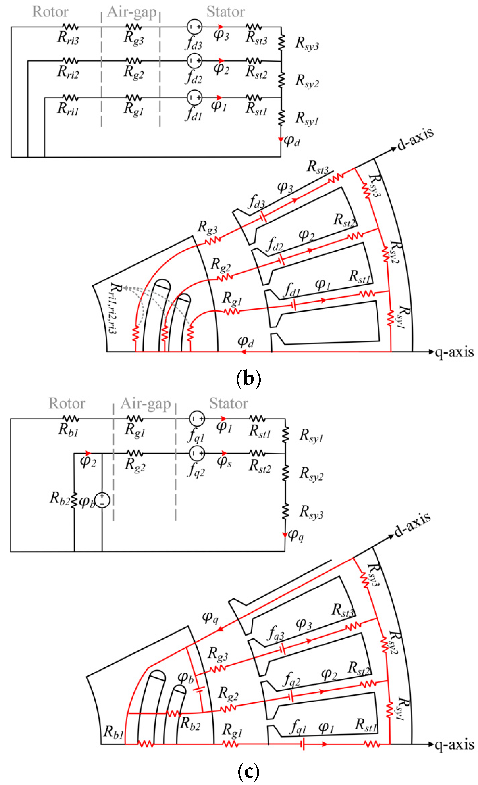
2.4. LPM: Lumped Parameter Model

A complete machine design knowledge is required to define the major flux paths and the machine’s model in the LPM, in which the magnetic saturations and other nonlinear effects are directly determined utilizing the steel sheet materials in the FEA. To determine the parameters of the motor, d-q axes MEC of the proposed models are developed as shown in Figure 6. The PM flux is oriented along the q-axis and the d-axis is aligned 90E. Deg. to the q-axis. The MEC, which is shown in Figure 6 is developed with two flux barriers filled with inset PMs, in which φd and φq are the d-q axes flux linkages, φg is the air-gap flux linkage, φM represents the PM flux linkage, φb is the saturation flux corresponding to the PM flux sources, fd and fq are the d-q axes magnetic potentials, and Rr, Rb, Rg, Rst and Rsy are the reluctances of the rotor islands, rotor flux barriers, air-gap, and stator core reluctances respectively. It should be noted that in comparison with the FEA, although solving such a nonlinear equation requires much smaller time steps, we have exported the LPM models to the FEM for detailed analysis results. As the stator reluctances are far lower than the air-gap reluctance, the proposed MEC in Figure 6 can be mathematically defined as:
  • d-axis (Figure 6b):
    R s y + R s t R g { φ 1 = f d 1 R g 1 + R r i 1 φ 2 = f d 2 R g 2 + R r i 2 φ 3 = f d 3 R g 3 + R r i 3
    φ d = φ 1 + φ 2 + φ 3
    L d = φ d i d
  • q-axis (Figure 6c):
    R s y + R s t R g { φ 1 = f q 1 R g 1 + R b 1 φ s = f q 2 + R b 2 φ b R g 2 + R b 2
    φ d = φ 1 + φ s
    L d = φ q i q

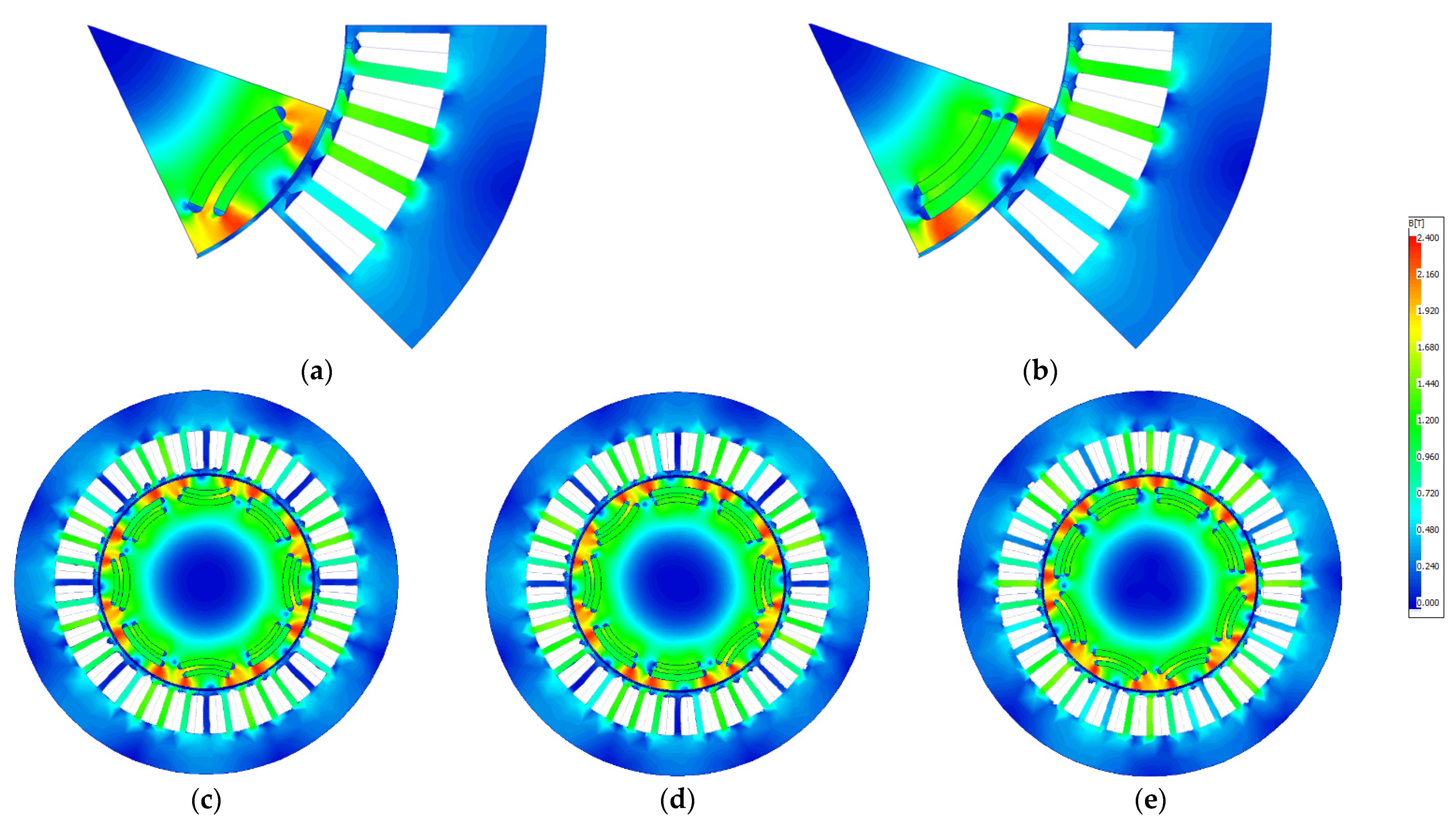
2.5. FEM: Finite Element Method

One of the most common numerical methods used to design, analyze, optimization and performance evaluation of electrical machines is the FEM. A 2D-FEM is applied in this study to calculate the torque developments, torque fluctuations, electromagnetic power, line-to-line Back-EMF, air-gap flux density, efficiency, and power factor with respect to the stator current phase angle, stator current amplitude, and rotor speed variations, for the proposed models of five-phase PMASynRM. The corresponding LPM models of the proposed configurations, shown in Figure 6b,c, are exported to the conducted FEA of this study for a more detailed electromagnetic (E-Magnetic) characteristic analysis.

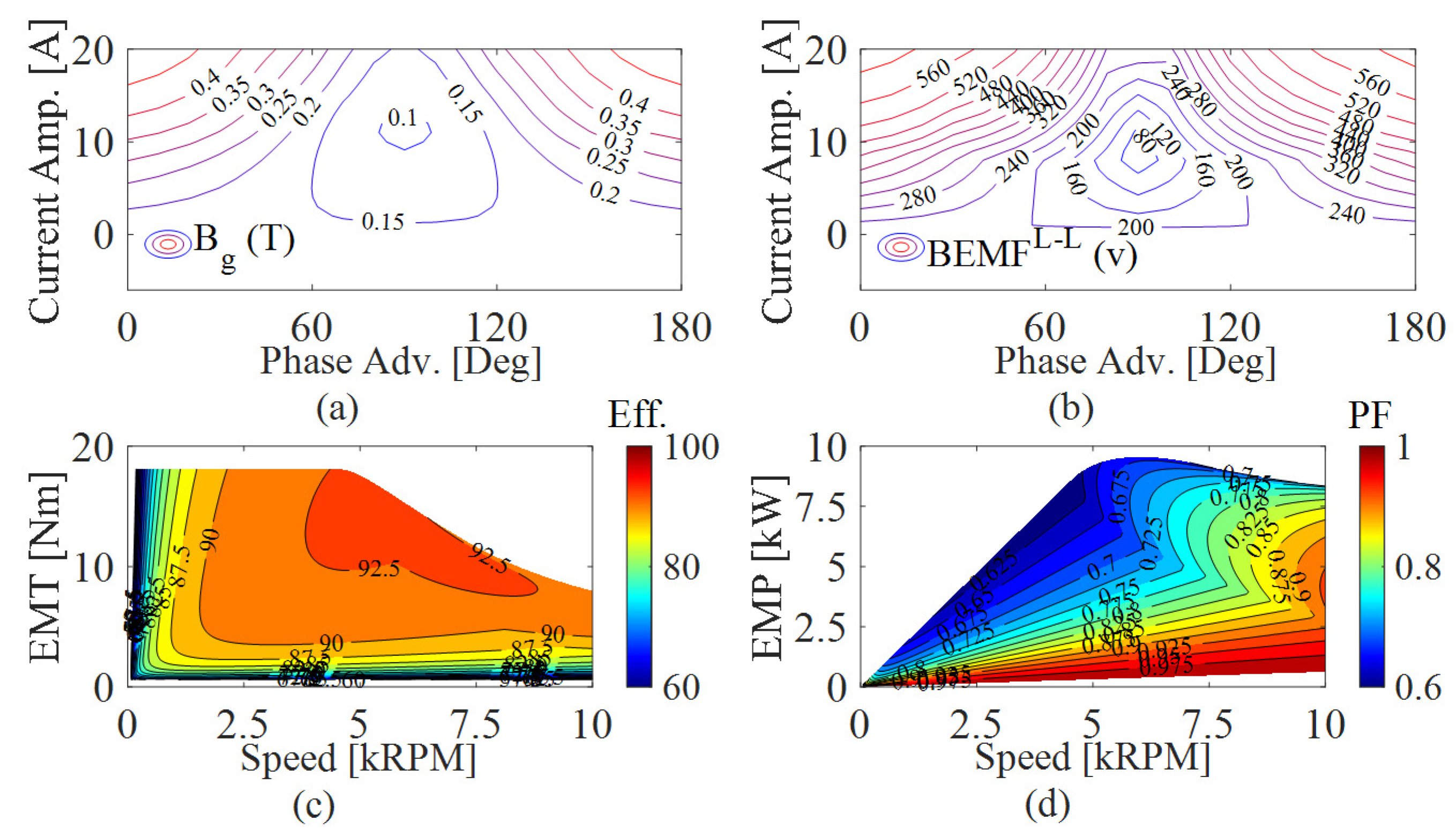
3. E-Magnetic FEM Results

In the following subsections, the conducted FEM analysis results are comparatively reported. First, the models are studied by applying the nominal current of 15 A operating at 5 kRPM of rotor speed. Then, the torque performance (average torque and torque ripple) of each model is sensitively investigated to determine the best-performed model, producing the lowest value of the torque ripple, with regard to the stator current specifications (Phase angle and Amplitude) variation. Finally, the torque, power, Back-EMF, air-gap flux density, efficiency, and power factor of the candidate model are studied considering a wide range of speeds.

3.1. Steady-State Analysis at Rated Current and Nominal Speed
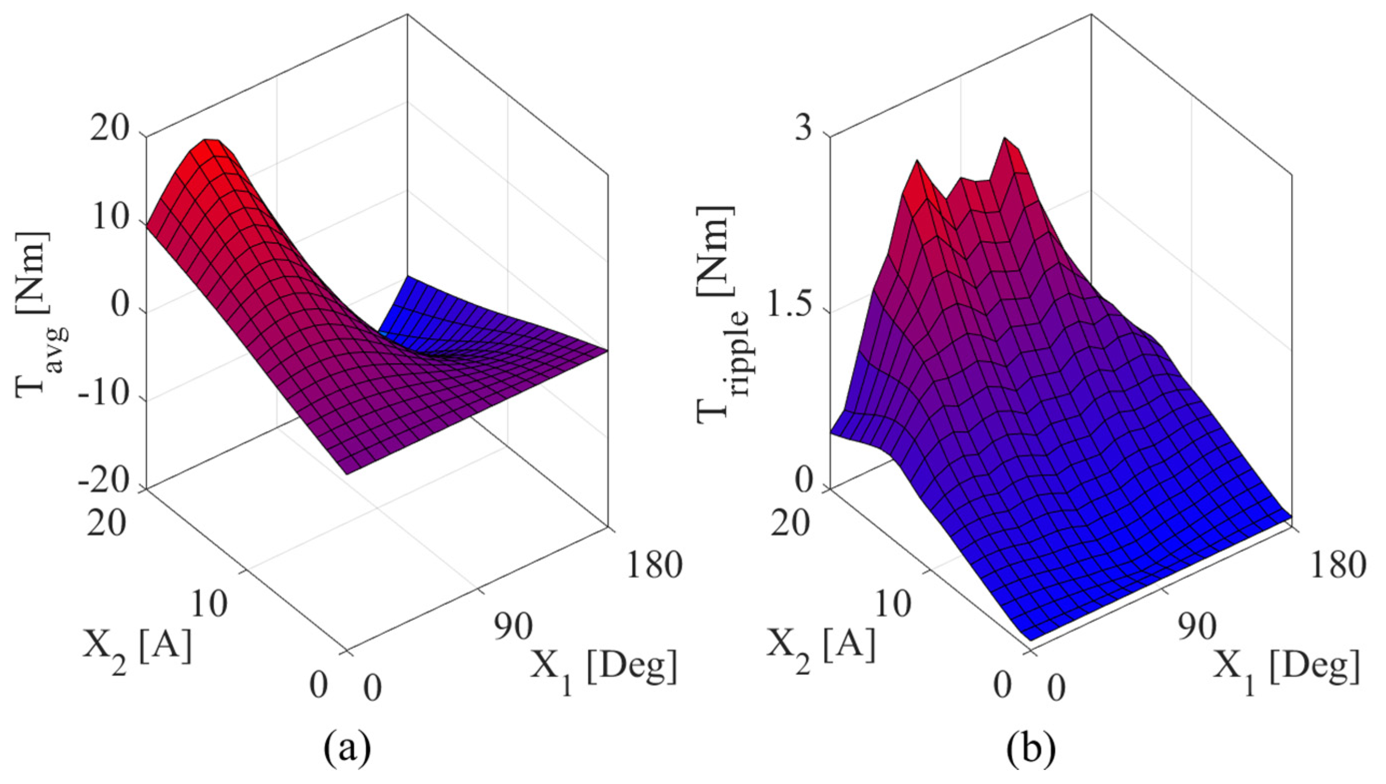
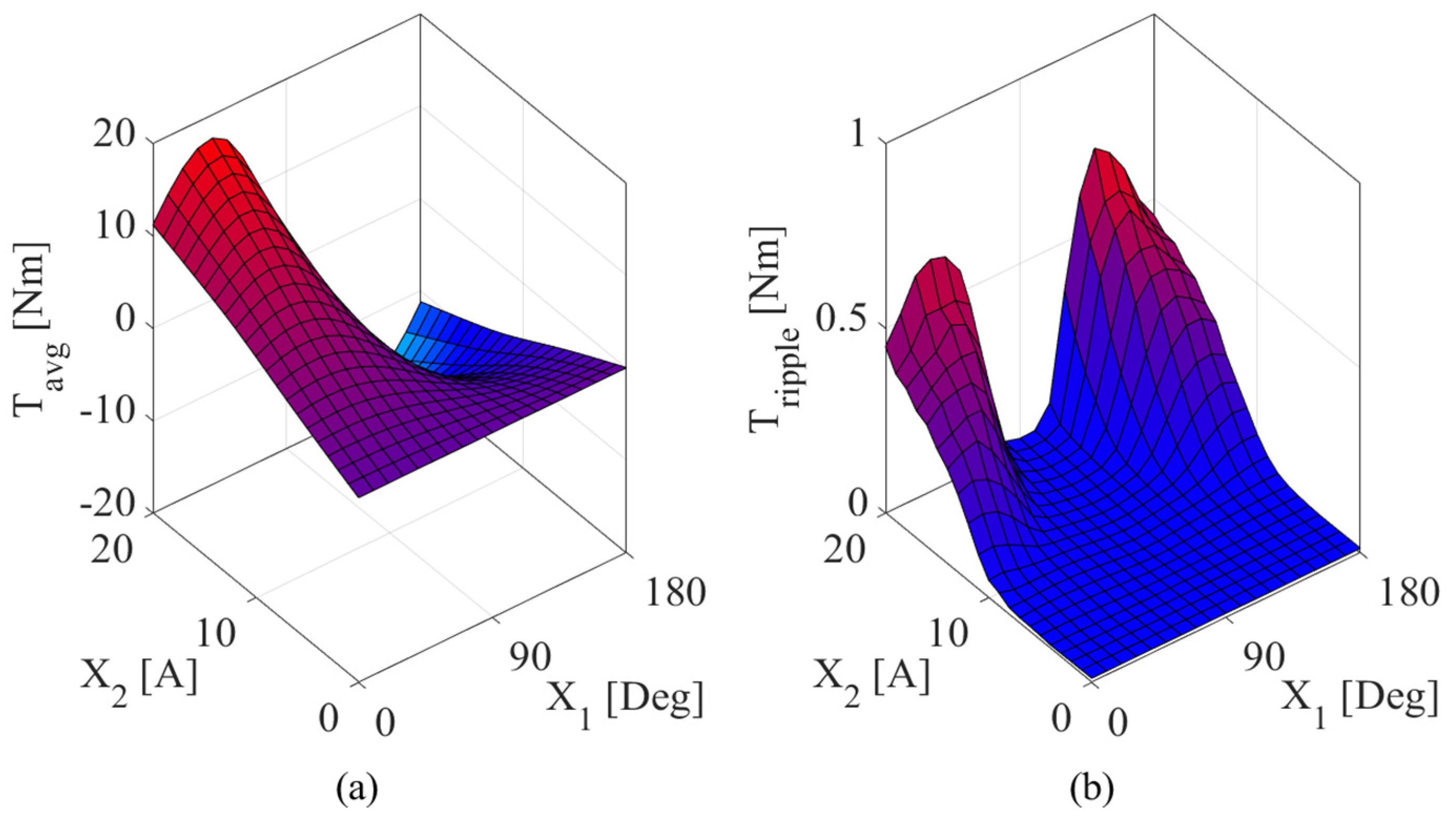
The steady-state operational behavior of the proposed models is illustrated in Figure 7 in which, Figure 7a,c,d depict the comparative torque performance (average torque, cogging torque, and torque ripple respectively). The Model-I and -II exhibit higher torque fluctuations; however, the Model-II produces the maximum average torque. The other models present a much lower value of cogging torque with desirable values of average torque (the value is in between that of the Model-I and -II), in which the Model-V provides the lowest TCog, and the Model-III presents the lowest TRipple. Figure 7b displays the Line-to-Line Back-EMF produced by the proposed models. Accordingly, Model-I and -II produce the minimum and maximum peak values, whereas the other models present medium levels of L-L Back-EMF. Figure 8 demonstrates the reluctance and PM torque comparison along with the harmonic behavior of the proposed structure. Accordingly, it can be seen from Figure 8a,b that there is a tradeoff between the reluctance part of the torque and the magnet part as they move in the opposite direction while reconfiguration occurred. However, the overall produced torque remained the same and approximately equal to 11.5 Nm for all of the proposed models. Based on the presented harmonic results in Figure 8c,d, the Model-I and -II suffer from high order torque and back-EMF harmonics, while Model-III to -V benefit from lower amplitudes of high order harmonics and consequently better performance is presented by them. The flux density distribution map for the proposed models is shown in Figure 9. It can be derived from Figure 9 that except for the local saturation in iron ribs, the total distributed flux density is desirable, causing a low probability of power losses, local saturation, and the chance of overheating under the nominal operational conditions. However, in comparison with the Model-I, the Model-II provides less local saturations. Based on Figure 9a,b and Equation (8), as the harmonics contents of the MMF of the rotor increase, a higher torque ripple will occur. In other words, in comparison with the Model-I and -II with the highest and lowest local saturations respectively, the local saturation in the Model-III to -V reduced due to the reconfiguration. Thus, a higher torque ripple with a lower value of torque is shown by the Model-I, and the highest torque and lower values of torque ripple are presented by the Model-II to -V, while the Model-III to -V provides a value of torque between that of the Model-I and -II. Thus, a noticeable torque sacrifice is prevented by reducing local saturations in the Model-III to -V and consequently provides better torque ripple performance. Also, as illustrated in Figure 8a,b, Model-V presents a wider range of operations in terms of the rotor speed. The calculated electromagnetic characteristics of the proposed models are reported in Table 3.

3.2. Optimization

Concerning the stator current phase angle (X1) and amplitude (X2) variations, the results achieved from the 2D-FEM, related to the average torque and torque ripple study, are illustrated in Figure 10, Figure 11, Figure 12, Figure 13 and Figure 14. It can be seen that the presented average torque is similar for all the proposed rotor schemes with some slight differences at the minimum and maximum variable extremes. However, higher values of average torque are determined for the Model-II to -V in comparison with the proposed PMASynRM model. In terms of torque ripple, as expected from the steady-state section, the Model-I and -II present high values of torque ripple (increased along with increasing values of X1 and X2), while others benefit from much lower value (begins with higher values but decline as X1 increased). Hence, the Model-V, which presents lower values of TRipple with respect to the variation of applied parameters is selected as the optimal model for Low-TRipple applications. Moreover, to precisely obtain the advantages of this candidate model to operate at a wide range of speed the following dynamic analysis is performed. Table 4. reports the Tmax and Tripple-min values for the proposed structures during variation of stator current amplitude and phase angle.

3.3. Optimal Rotor Scheme

Based on the illustrated results of the performed sensitivity analysis in the previous subsection, the Model-V is selected to be studied under dynamic performance. Figure 15 demonstrated the performance of the Model-V under dynamic analyzes. Figure 15a,b show the average air-gap flux density (Bg) and L-L Back-EMF of the Model-V, operating at desired values up to 0.4 T and over 500 v respectively, at a maximum stator current amplitude of 20 A. The efficiency and power factor map of the Model-V are illustrated in Figure 15c,d respectively. Accordingly, high values of efficiency are observed at constant torque region for up to 5 kRPM of speed. Higher values of power factor are observed when the candidate model operates at the constant power region for more than 5 kRPM. Overall, the selected Model-V present higher values of torque/power density, efficiency, power factor, and Back-EMF with a much lower amount of torque fluctuations in comparison with the conventional PMASynRM, which make this model a vital alternative, applicable for Low-TRipple applications, operating in a wide range of speed up to 10 kRPM.

4. Conclusions

The goal of this paper is to introduce and study novel rotor flux barrier reconfigurations for a five-phase PMASynRM, in which a conventional PMASynRM is considered to observe the benefits of the presented rotor schemes. The models are designed in following the formerly investigated rotor design criteria so that although the proposed structures are designed considering the same design parameter values, the flux barrier scheme has been reconfigured, and consequently results in different performances. An LPM conducted to a 2D FEM is applied to the proposed models under the steady-state condition at rated current and speed. Based on the FEM results, the maximum torque, minimum TCog, and TRipple are presented by the Model-II, Model-V, and Model-III respectively compared to the PMASynRM. Higher local saturations in the Model-I resulted in high order MMF harmonic contents and therefore increased the torque ripple. To minimize the torque reduction in the Model-III to -V, their scheme is considered the combination of the Model-I and -II, which led to a desirable performance without a noticeable torque reduction. Since the goal of this paper is to investigate torque development, particularly the torque ripple reduction, by performing a sensitivity analysis, including stator current phase angle (X1) and amplitude (X2), the proposed machines provide similar average torque performance with respect to the variation of these parameters. However, the torque ripple highly decreased in Model-III to -V with an increasing value of X2 up to 90E. Deg., while Model-I and -II suffer from high values of TRipple (increased along with increasing values of X1 and X2). Overall, the Model-V, which provides high values of torque density along with a much lower amount of torque ripple is selected as the optimal rotor scheme for five-phase PMASynRM. To obtain the advantages of the optimal model, it is studied under the dynamic condition for a wide range of operational speeds. As a result, the optimal model operates at high values of constant torque, power, efficiency, and power factor with desirable values of Line-to-Line Back-EMF and air-gap flux density. Hence, the optimal model is applicable for Low-TRipple High-Speed applications with no extra manufacturing costs when transforming from a conventional PMASynRM rotor scheme to the Model-V.

Author Contributions

Conceptualization, H.G. and M.M.; software, H.G. and M.M.; validation, M.M., and M.B.; writing—original draft preparation, H.G.; writing—review and editing, M.M., and M.B.; supervision, M.M., and M.B. All authors have read and agreed to the published version of the manuscript.

Funding

This research received no external funding.

Conflicts of Interest

The authors declare no conflict of interest.

References

  1. Li, J.; Wang, K. A Novel Spoke-Type PM Machine Employing Asymmetric Modular Consequent-Pole Rotor. IEEE ASME Trans. Mechatron. 2019, 24, 2182–2192. [Google Scholar] [CrossRef]
  2. Heidari, H.R.; Andriushchenko, E.; Rassolkin, A.; Kallaste, A.; Vaimann, T.; Demidova, G.L. Comparison of Synchronous Reluctance Machine and Permanent Magnet-Assisted Synchronous Reluctance Machine Performance Characteristics. In Proceedings of the 27th International Workshop on Electric Drives: MPEI Department of Electric Drives 90th Anniversary (IWED), Moscow, Russia, 27–30 January 2020. [Google Scholar] [CrossRef]
  3. Moradian, M.R.; Soltani, J.; Najjar-Khodabakhsh, A.; Arab Markadeh, G.R. Adaptive Torque and Flux Control of Sensorless IPMSM Drive in the Stator Flux Field Oriented Reference Frame. IEEE Trans. Ind. Inform. 2019, 15, 205–212. [Google Scholar] [CrossRef]
  4. Moradian, M.R.; Soltani, J.; Benbouzid, M.; Najjar-Khodabakhsh, A. A Parameter Independent Stator Current Space-Vector Reference Frame-Based Sensorless IPMSM Drive Using Sliding Mode Control. Energies 2021, 14, 2365. [Google Scholar] [CrossRef]
  5. Ghorbani, H.R.; Majidi, B. Power Density Optimization through Optimal Selection of PM properties in a PM-SyncRM Using FEM Analysis. In Proceedings of the 2019 10th International Power Electronics, Drive Systems and Technologies Conference (PEDSTC), Shiraz, Iran, 12–14 February 2019. [Google Scholar] [CrossRef]
  6. Ghorbani, H.; Moradian, M. Torque pulsation reduction in five-phase PMASyncRMs. J. Power Electron. 2021, 1–10. [Google Scholar] [CrossRef]
  7. Krichen, M.; Elbouchikhi, E.; Benhadj, N.; Chaieb, M.; Benbouzid, M.; Neji, R. Motor Current Signature Analysis-Based Permanent Magnet Synchronous Motor Demagnetization Characterization and Detection. Machines 2020, 8, 35. [Google Scholar] [CrossRef]
  8. Agarlita, S.; Ursu, D.; Tutelea, L.; Boldea, I.; Fahimi, B. BLDC multiphase reluctance machines: A revival attempt with 2D FEM investigation and standstill tests. In Proceedings of the IEEE Energy Conversion Congress and Exposition, Denver, CO, USA, 15–19 September 2013. [Google Scholar] [CrossRef]
  9. Maroufian, S.S.; Pillay, P. Design and Analysis of a Novel PM-Assisted Synchronous Reluctance Machine Topology with AlNiCo Magnets. IEEE Trans. Ind. App. 2019, 55, 4733–4742. [Google Scholar] [CrossRef]
  10. Chen, K.; Yu, W.; Wen, C. Rotor Optimization for Synchronous Reluctance Motors. CES Trans. Electr. Mach. Syst. 2019, 3, 279–284. [Google Scholar] [CrossRef]
  11. Jurca, F.N.; Inte, R.; Martis, C. Optimal rotor design of novel outer rotor reluctance synchronous machine. Electr. Eng. 2020, 102, 107–116. [Google Scholar] [CrossRef]
  12. Inte, R.A.; Jurca, F.N.; Martis, C. Design and Analysis of Outer Rotor Permanent Magnet Assisted Synchronous Reluctance Machine with Concentrated Winding for Small Electric Propulsion. In Proceedings of the AEIT International Annual Conference (AEIT), Florence, Italy, 18–20 September 2019. [Google Scholar] [CrossRef]
  13. Mohanarajah, T.; Nagrial, M.; Rizk, J.; Hellany, A. A Novel Method to Optimize Permanent Magnet Assisted Synchronous Reluctance Machines. Electr. Power Comp. Syst. 2020, 48, 933–944. [Google Scholar] [CrossRef]
  14. Zeraoulia, M.; Benbouzid, M.; Diallo, D. Electric Motor Drive Selection Issues for HEV Propulsion Systems: A Comparative Study. IEEE Trans. Veh. Tech. 2006, 55, 1756–1764. [Google Scholar] [CrossRef] [Green Version]
  15. Aryasomayajula, S.B.; Banerjee, R.; Sensarma, P. Effect of Magnets and Diamagnetic Material on Performance of SynRM with Novel Rotor Structure. In Proceedings of the National Power Electronics Conference (NPEC), Tiruchirappalli, India, 13–15 December 2019. [Google Scholar] [CrossRef]
  16. Hezzi, A.; Elghali, S.B.; Bensalem, Y.; Zhou, Z.; Benbouzid, M.; Abdelkrim, M.N. ADRC-Based Robust and Resilient Control of a 5-Phase PMSM Driven Electric Vehicle. Machines 2020, 8, 17. [Google Scholar] [CrossRef]
  17. Wang, S.; Ma, J.; Liu, C.; Wang, Y.; Lei, G.; Guo, Y.; Zhu, J. Design and performance analysis of a novel synchronous reluctance machine. Int. J. Appl. Electromagn. Mech. 2020, 63, 249–265. [Google Scholar] [CrossRef]
  18. Liu, Z.; Hu, Y.; Wu, J.; Zhang, B.; Feng, G. A Novel Modular Permanent Magnet-Assisted Synchronous Reluctance Motor. IEEE Access 2021, 9, 19947–19959. [Google Scholar] [CrossRef]
  19. Zhao, W.; Shen, H.; Lipo, T.A.; Wang, X. A New Hybrid Permanent Magnet Synchronous Reluctance Machine with Axially Sandwiched Magnets for Performance Improvement. IEEE Trans. Energy Convers. 2018, 33, 4. [Google Scholar] [CrossRef]
  20. Cai, W.; Wu, X.; Zhou, M.; Liang, Y.; Wang, Y. Review and Development of Electric Motor Systems and Electric Powertrains for New Energy Vehicles. Automot. Innov. 2021, 4, 3–22. [Google Scholar] [CrossRef]
  21. Cui, W.; Hu, B.; Pan, T. A Novel PMSM with Optimized Asymmetric Eccentric Air-Gap for High-Power Electric Motorcycle. Electr. Power Compon. Syst. 2019, 47, 1854–1863. [Google Scholar] [CrossRef]
  22. Momen, F.; Rahman, K.; Son, Y. Electrical Propulsion System Design of Chevrolet Bolt Battery Electric Vehicle. IEEE Tran. Ind. App. 2018, 55, 376–384. [Google Scholar] [CrossRef]
  23. Tawfiq, K.B.; Ibrahim, M.N.; El-Kholy, E.E.; Sergeant, P. Performance Improvement of Existing Three Phase Synchronous Reluctance Machine: Stator Upgrading to 5-Phase with Combined Star-Pentagon Winding. IEEE Access 2020, 8, 143569–143583. [Google Scholar] [CrossRef]
  24. Toliyat, H.A.; Waikar, S.P.; Lipo, T.A. Analysis and simulation of five-phase synchronous reluctance machines including third harmonic of air gap MMF. IEEE Trans. Industry App. 1998, 34, 332–339. [Google Scholar] [CrossRef] [Green Version]
  25. Shen, J.-X.; Lin, Y.-Q.; Sun, Y.; Qin, X.-F.; Wan, W.-J.; Cai, S. Permanent Magnet Synchronous Reluctance Machines with Axially Combined Rotor Structure. IEEE Tran. Magn. 2021. [Google Scholar] [CrossRef]
  26. Mohammadi, A.; Mirimani, S.M. Design of a Novel PM-Assisted Synchronous Reluctance Motor Topology Using V-Shape Permanent Magnets for Improvement of Torque Characteristic. IEEE Tran. Energy Convers. 2021. [Google Scholar] [CrossRef]
  27. Korman, O.; Degano, M.; Nardo, M.D.; Gerada, C. A Novel Flux Barrier Parametrization for Synchronous Reluctance Machine. IEEE Tran. Energy Convers. 2021. [Google Scholar] [CrossRef]
  28. Wang, K.; Zhu, Z.Q.; Ombach, G.; Koch, M.; Zhang, S.; Xu, J. Optimal slot/pole and flux-barrier layer number combinations for synchronous reluctance machines. In Proceedings of the Eighth International Conference and Exhibition on Ecological Vehicles and Renewable Energies (EVER), Monte Carlo, Monaco, 27–30 March 2013. [Google Scholar] [CrossRef]
  29. Scmidt, E.; Brandl, W. Comparative finite element analysis of synchronous reluctance machines with internal rotor flux barriers. In Proceedings of the IEEE International Electric Machines and Drives Conference (IEMDC), Cambridge, MA, USA, 17–20 June 2001. [Google Scholar] [CrossRef]
  30. Wang, Y.; Ionel, D.; Dorrell, D.G.; Stretz, S. Establishing the power factor limitations for synchronous reluctance machines. IEEE Trans. Magn. 2015, 51, 8111704. [Google Scholar] [CrossRef]
  31. Bianchi, N.; Bolognani, S.; Bon, D.; Pre, M.D. Torque harmonic compensation in a synchronous reluctance motor. IEEE Trans. Energy Convers. 2008, 23, 466–473. [Google Scholar] [CrossRef]
  32. Moghaddam, R.; Gyllensten, F. Novel high-performance SynRM design method: An easy approach for a complicated rotor topology. IEEE Trans. Ind. Electron. 2014, 61, 5058–5065. [Google Scholar] [CrossRef]
  33. Baek, J.; Bonthu, S.S.R.; Choi, S. Design of five-phase permanent magnet assisted synchronous reluctance motor for low output torque ripple applications. IET Electr. Power App. 2016, 10, 339–346. [Google Scholar] [CrossRef]
  34. Bilyi, V.; Bilyi, D.; Oleg, M.; Dajaku, G.; Gerling, D. Synchronous reluctance machine with multiphase stator cage winding. In Proceedings of the 20th International Conference on Electrical Machines and Systems (ICEMS), Sydney, Australia, 11–14 August 2017. [Google Scholar] [CrossRef]
Figure 1. Proposed Models: (a) Model-I (PMASynRM), (b) Model-II, (c) Model-III, (d) Model-IV and (e) Model-V.
Electronics 11 00041 g001
Figure 2. PMASynRM Structural Design and Winding Pattern.
Electronics 11 00041 g002
Figure 3. Winding: (a) Factor, (b) MMF.
Electronics 11 00041 g003
Figure 4. Evaluation Procedure.
Electronics 11 00041 g004
Figure 5. Main Design Parameters of the Rotor.
Electronics 11 00041 g005
Figure 6. PMASynRM: (a) Phasor Diagram, (b) d-axis MEC, and (c) q-axis MEC.
Electronics 11 00041 g006aElectronics 11 00041 g006b
Figure 7. FEA results at rated current: (a) Average Torque, (b) L-L Back-EMF, (c) Cogging Torque and (d) Torque Ripple.
Electronics 11 00041 g007
Figure 8. FEA results at rated current: (a) Reluctance Torque, (b) PM Torque, (c) Tavg Harmonics, and (d) Back-EMF Harmonics.
Electronics 11 00041 g008
Figure 9. Flux Density Distribution Map: (a) Model-I (PMSynRM), (b) Model-II, (c) Model-III, (d) Model-IV and (e) Model-V.
Electronics 11 00041 g009
Figure 10. FEA results for torque performance of the PMASynRM: (a) Average Torque, and (b) Torque Ripple.
Electronics 11 00041 g010
Figure 11. FEA results for torque performance of the Model-II: (a) Average Torque, and (b) Torque Ripple.
Electronics 11 00041 g011
Figure 12. FEA results for torque performance of the Model-III: (a) Average Torque, and (b) Torque Ripple.
Electronics 11 00041 g012
Figure 13. FEA results for torque performance of the Model-IV: (a) Average Torque, and (b) Torque Ripple.
Electronics 11 00041 g013
Figure 14. FEA results for torque performance of the Model-V: (a) Average Torque, and (b) Torque Ripple.
Electronics 11 00041 g014
Figure 15. Dynamic Performance Results of the Model-V: (a) Bg, (b) L-L Back-EMF, (c) Efficiency Map, and (d) Power Factor Map.
Electronics 11 00041 g015
Table 1. Design Constrains.
ParameterSym.ValueUnit
Number of Phasesm5-
Number of Stator SlotsNS40-
Number of Rotor PolesNP8-
Rated Speednr5krpm
Input CurrentIn15A
DC Bus VoltageVDC400v
Stator Outer DiameterDSO160mm
Stator Inner DiameterDSI90mm
Rotor Outer DiameterDRO89.15mm
Shaft DiameterDSh29mm
Stack LengthLm90mm
PM ArcLPM35°Mech.
Air-Gap LengthLg0.85mm
Steel Material-M800-50A-
PM Material-N42SH-
PM Mass-0.5kg
Steel Laminations Mass (Rotor & Stator)-11.16kg
Copper Wire Mass (AWG 18)-3.35kg
Total Mass (Excluding the Shaft)-15kg
Table 2. Rotor Design Parameters.
Model/ParameterKWb1Wb2Wi1Wi2WribdrUnit
Model-I0.473462330mm
Model-II0.5444
Table 3. FEA Results at Rated Speed and Current.
ParameterUnitIIIIIIIVV
TavgNm11.0211.611.411.3711.35
TCogNm0.10.050.0250.0350.022
TRipple%5.92.952.82.932.85
η%93.894.7593.9494.294.1
PF-0.650.770.710.710.71
LdmH6.075.9446.035.996
LqmH11.0410.8710.9810.9710.97
Table 4. Optimization summarized reports.
Model-IModel-IIModel-IIIModel-IVModel-V
Tmax [Nm]16.518.1317.6617.617.7
Tripple [Nm]1.770.80.850.830.6
X1 [Deg]4040404040
X2 [A]2020202020
Publisher’s Note: MDPI stays neutral with regard to jurisdictional claims in published maps and institutional affiliations.

