Article

Wideband Singly Fed Compact Circularly Polarized Rectangular Dielectric Resonator Antenna for X-Band Wireless Applications

1
Department of Electrical and Computer Engineering, COMSATS University Islamabad-Abbottabad Campus, Abbottabad 22060, Pakistan
2
Department of Computer Science, COMSATS University, Islamabad-Abbottabad Campus, Abbottabad 22060, Pakistan
3
Department of Electrical Engineering, University of Engineering and Technology Peshawar, Peshawar 25120, Pakistan
4
Department of Computer Systems Engineering, University of Engineering and Technology Peshawar, Peshawar 25120, Pakistan
5
Department of Electronics Engineering Technology, University of Technology Nowshera, Nowshera 24100, Pakistan
6
Department of Information Technology, College of Computer and Information Sciences, Princess Nourah bint Abdulrahman University, P.O. Box 84428, Riyadh 11671, Saudi Arabia
*
Authors to whom correspondence should be addressed.
Electronics 2022, 11(20), 3281; https://doi.org/10.3390/electronics11203281
Submission received: 6 September 2022 / Revised: 4 October 2022 / Accepted: 8 October 2022 / Published: 12 October 2022

Abstract

:
This work focuses on a compact circularly polarized wideband rectangular dielectric resonator antenna (RDRA) for X-band wireless applications. The wideband response of the RDRA is initially generated by a coaxial probe, a compact RDR, an air gap in the DR and a slot of rectangular shape in the ground. The circular polarization is achieved via incorporation of a unique feeding mechanism. The edge feeding of the RDRA with a coaxial probe generates the orthogonal modes in RDRA that make the design polarized circularly. The axial ratio performance is improved by adding a copper strip on the top of the DR. To validate the simulated results, the prototype design is fabricated and measured results are noted. For −10 dB reference value, the prototype has 59.74% impedance bandwidth (8.45–14.09 GHz). For 3 dB reference value of the axial ratio, the prototype has 9.24% Circular Polarization (CP) performance (10.084–11.084 GHz). The design has 6.5 dBic peak gain and 95.5% peak efficiency. Results show that simulated results are in close agreement with the measured results.

1. Introduction

Modern wireless communication technologies are of great significance in bringing an ease to human lives in uncountable fields like reliable and efficient distant communication, remotely automated and robot controlled machines, machine-to-machine communication, internet of things (IoT), unmanned transportation systems, smart grid concepts in power transmission and distribution, digital banking systems, smart home HDTV through efficient satellite communication systems, real-time remote medical facilities and many more [1]. With the rapid evolution in past few decades of wireless communication technologies, antenna engineers are striving to develop innovative and efficient ways for the continuous and uninterrupted communication with perfect and consistent reception of the signals. Some discover the potential of Circularly Polarized (CP) antennas, which are more effective as compared to Linearly Polarized (LP) antennas in terms of efficient signal matching, high reflectivity, mitigating polarization mismatch, resistance to extreme weather situations, lessening the multipath interference between the signals, high-level absorption rate, insensitivity towards orientation between transmitter and receiver antennas, and high resistance to Faraday rotation effects [1,2,3,4,5,6,7,8,9,10,11,12,13] Polarization is the orientation of the electric field in electromagnetic waves (EMW), hence LP antennas always require accurate alignment of the transmitting and receiving antennas for efficient communication [14].
Generating circular polarization involves the excitation of two near-degenerate equal amplitudes and in phase quadrature orthogonal resonant modes [15]. Impedance bandwidth of the antennas depends on the feeding position and techniques. CP antenna performance depends on the overlapping of the operational impedance bandwidth (having return loss less than −10 dB or VSWR (Voltage Standing Wave Ratio) in between 1 and 2) and an Axial Ratio (AR) bandwidth (less than 3 dB) [16]. Considering the unique properties of CP antennas, multiple CP based antenna techniques are extensively practiced in different wireless communication industries like the cellular communication industry, navigation, radar and satellite communication systems. A great deal of academic and industrial research has been carried out to devise novel techniques for circular polarization. As a result, various types of antennas have been proposed in due course of time [17,18,19,20,21,22].
An advanced wireless communication industry requires low profile compact wideband characteristic antennas. As a result, academic and professional antenna designers today are exclusively committed to discovering antennas with a low-quality factor (Q factor) and highly efficient radiation [23,24]. Dielectric Resonator Antennas (DRAs) are the best possible and emerging antenna technology to fulfill these demands. DRAs are inherently free from metallic losses due to the dielectric nature of the radiator, have insignificant surface waves, wide impedance bandwidth characteristics, high radiation efficiency, high gain, simple excitation methods, inexpensive in nature, and have more degree of design freedom in various shapes like rectangular, triangular and cylindrical [25,26]. Moreover, relative permittivity and three-dimensional physical size of the Dielectric Radiators (DRs) provide different aspect ratios which include length-to-width and depth-to-width ratios of rectangular shape, central radius of hemispherical shape and height to radius of cylindrical shape are used to easily adjust the resonant frequency of the DRAs [27]. Consequently, DRAs have emerged as an alternative to the low-gain conventional antennas like monopoles, dipoles and Microstrip Patch Antennas (MPAs), especially in the upper microwave and lower millimeter wave frequency bands [28].
The circularly Polarized Dielectric Resonator Antenna (CP DRA) has gained much attention from the antenna designers due to the combined features of both circular polarization and DRs (low cost, low loss, extra design flexibility). There are two different approaches for the circular polarization in DRAs: single feed approach and dual/complex feed approach. Single feeding approach includes slot coupled feeding, m-line feed and coaxial probe feed. Dual/Complex feeding is effective to achieve wide AR bandwidth. The drawback is circuit complexity, increased loss, high cost and making the design bulkier [29]. Thus, to design compact, cost effective and wide AR bandwidth CP DRAs, researchers prefer to adopt the simple feeding mechanism. Researchers have devised multiple techniques to obtain circular polarization. These include stair shaped DR, stacked DR, spidron fractal geometry DR and many more.
A circularly polarized quarter wave fed DRA prototype for C and X-band UWB applications with overall size of 25 × 25 × 8 mm3 is proposed in [29]. The design has a maximum gain of 6 dBic, 63.8% of Impedance Bandwidth (IBW) and 63.8% of AR bandwidth. It comprises of two rectangular shaped DRs and F-shaped defected ground structure. An extra-large size of 90 × 90 × 15 mm3 slot coupled circularly polarized DRA with two annular vias in the radiator, having −10 dB operational bandwidth of 7.29% and 3 dB AR bandwidth of 5.5% with peak gain of 6–7.1 dBic, is reported in [30]. In [31], an AMC (Artificial Magnetic Conductor) based miniaturized DRA is proposed. The design operates at 3.5 GHz of 5G band with 14.2% impedance bandwidth. The design has over all dimensions of 50 × 50 × 6.6 mm3. The gain and efficiency of the design are 6.87 dBic and 74% respectively. Although the design is compact and has good overall performance, but the drawback is that it is not circularly polarized. For C band satellite communication application, lower Ku band and overall UW dual band CP characteristics are achieved with the help of I-shaped monopole and two rectangular shaped orthogonally placed dielectric radiators, which is presented in [32]. The proposed design has a large size of 63 × 75 × 6.08 mm3. Moreover, peak gain of 7 dBic with IBW of 146.33% and AR BW for first and second band are 17.28% and 11.56%, respectively. In [33], five layers CP DRA with stacked rectangular radiators fed by substrate integrated waveguide is discussed. The design has dimensions of 23 × 23 × 2 mm3 with AR BW of 27%, IBW of 30% and peak gain of 6.5 dBic for Ku-band satellite communication. A long heighted dual mode CP RDRA of the size 40 × 40 × 18 mm3, fed with stair-shaped microstrip line, operating in the range of 2.9 to 3.9 GHz for Worldwide Interoperability for Microwave Access (Wi-MAX) applications is discussed in [34]. The design has an AR BW of 17.5% and peak gain of 4.2 dBic. In [35] a CP Cylindrical Dielectric Resonator Antenna (CDRA) with a microstrip line edge feeding and a J-shaped modified defected ground for WI-MAX and LTE applications is discussed in detail. The proposed design has a size of 40 × 32 × 14 mm3. The design has IBW of 41.44%, an AR BW of 29.91% and maximum gain of 2.84 dBic. In [36] an extra large sized low gain CP RDRA with improved AR BW of 55.22% and IBW of 66.45%, possessing peak gain of 6.5 dBic and large size of 80 × 80 × 5 mm3, is presented. The design is excited with a microstrip line, coupled with stair-shaped slotted defected ground and edged-cut dielectric resonator with conductive coating. In [37] a slot coupled square shaped CP Dielectric Resonator Antenna (CP SDRA) for WLAN applications with off centered microstrip line feeding is discussed. The design has overall dimensions of 44 × 45 × 11 mm3, with −10 dB return loss of 9.25% and an AR BW of 7.94%, respectively. In [38], a long heighted passive metal strip loaded and coaxial fed C-shaped CP RDRA for WI-MAX is presented. The design has a size of 45 × 40 × 15 mm3. The design has gain of 5.2 dBic with IBW and an AR BW of 24.72% and 12.28%, respectively. Whereas in [39], an inverted sigmoid shaped CP dual band DRA with passive loaded metallic strip is discussed. The design has an AR BW in lower and upper bands of 19.98% and 3.07%, respectively. The design has overall dimensions of 50 × 50 × 5 mm3. In [40] a novel complex dual facet spiral loop coupled equilateral triangular shaped dual band CPDRA is discussed. The design has overall dimensions of 50 × 50 × 10 mm3 with an AR BW of 1.6% in the first band and 1.8% in the second band, respectively. The design has peak gain of 2.2 dBic and 3.7 dBic for both the operating bands, respectively. The proposed design is used for sensing applications. In [41], probe fed periodically deformed cylindrical CP DRA is proposed. The design has a large size of 50 × 50 × 16 mm3 with IBW of 46.15%, an AR BW of 7.7% and an average peak gain of 5 dBic. In [42] a complex dual vertical microstrip fed CP CDRA is proposed. The design has large dimensions of 55 × 55 × 23 mm3 with reasonable peak gain of 5.5 dBic, simulated AR BW of 23.07% and IBW of 29.78% for airport surveillance radar (2.7–2.9 GHz) and Wi-MAX (3.3–3.6 GHz) applications. In [43], triangular ring-shaped aperture coupled microstrip line fed dual band CP RDRA is discussed. The design has a size of 40 × 40 × 8 mm3. The design is proposed for Wi-MAX and WLAN applications. The design has an average gain of 5.3 and 5.7 dBic, low AR BW of 1.03% and 3.4%, IBW of 2.58% and 15.78% in the upper and lower band, respectively.
From the above literature review, it is clear that a compact DRA with a wideband response and a good CP performance is highly preferred. All of the above designs are either bulky, complex or have poor performances. Therefore, an antenna with simple design, compact size and good performance is highly demanded. To achieve all these packages in a single design is very challenging. In this work, a very compact wideband CP DRA for X-band wireless application is discussed in detail. The design is very compact with only 5.175 mm height of the DR. The corner feeding excites two orthogonal modes in the DR, thus making the design CP. The top copper strip further enhances the axial ratio performance. For improving the operating band and impedance matching, an air gap is added at the center of the DR. A ground slot is etched which further improves these parameters. To the best of the authors’ knowledge, this is the most compact CP DRA with a very wide band response for the target X-band wireless application. The rest of the paper is organized as: Section 2 discusses the antenna geometry and design; Section 3 presents detail of the antenna design and analysis; Section 4 consists of the parametric study of the design; Section 5 gives detail of the final simulated and measured results and Section 6 concludes the proposed work.

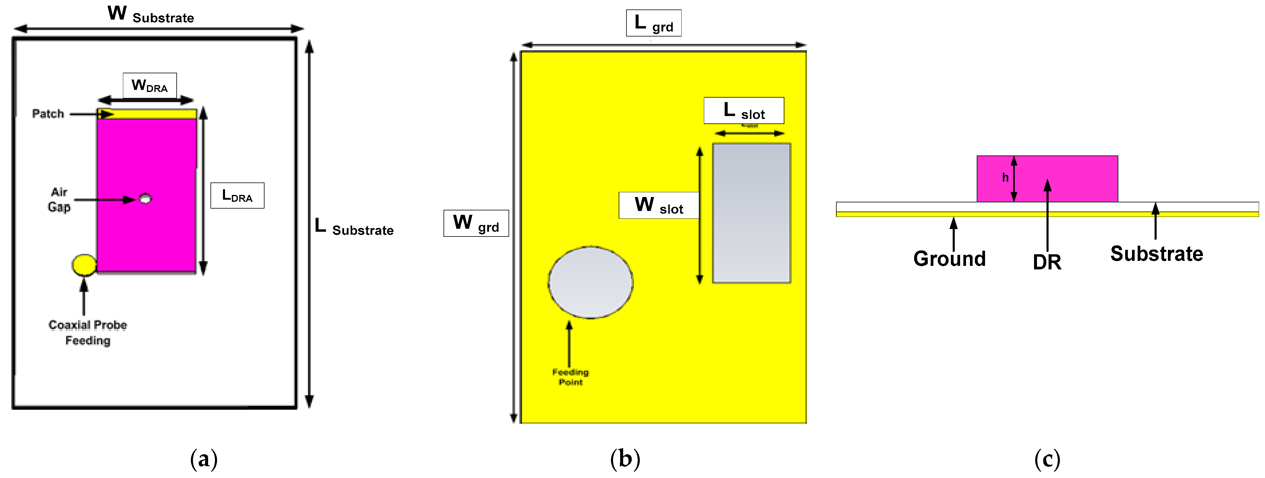
2. Antenna Geometry and Design

The proposed simple and compact CP DRA antenna design consists of a Dielectric Resonator (DR), substrate, coaxial probe feeding and a copper strip on the top of the DR. The initial dimensions of the DR are finalized with the help of the Dielectric Wave Guide model (DWM) [3,23]. A slot of rectangular shape is also carved in the ground plane. Figure 1a,b and c suggests the detailed geometry of the proposed design. The DR has dimensions of LDR, WDR and h, which are the length, width and height of the DR, respectively, while its permittivity is 10.2. The DR is positioned on the top surface of the substrate which consists of Roger material with 2.33 relative permittivity (ϵr) and loss tangent tanδ = 0.0012. Lsub and Wsub are the length and width of the substrate. Lslot and Wslot are the dimensions of the ground slot. A stacked metallic strip on the top of the DR has the same width as that of the DR while having 1 mm length. The details of the dimensions are given in Table 1.

3. Antenna Design and Analysis
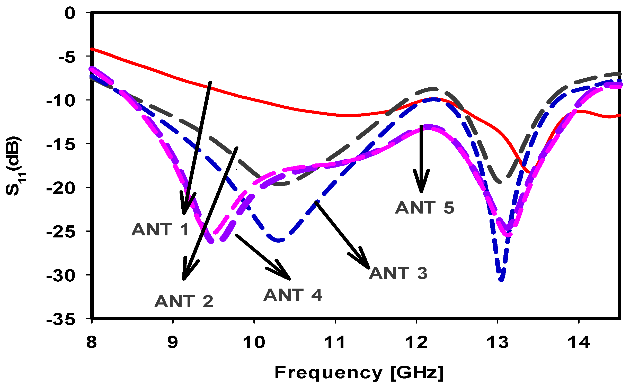
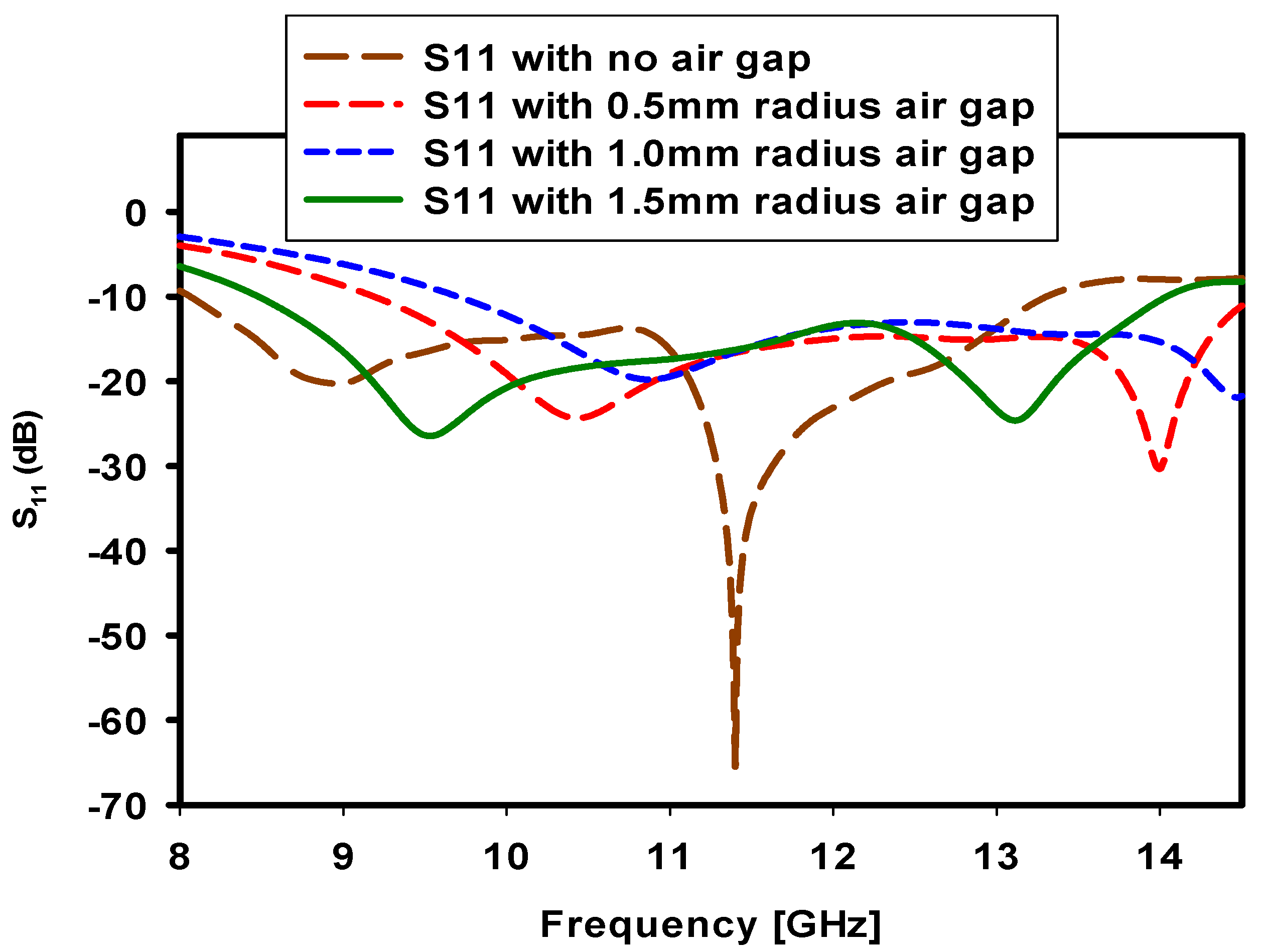
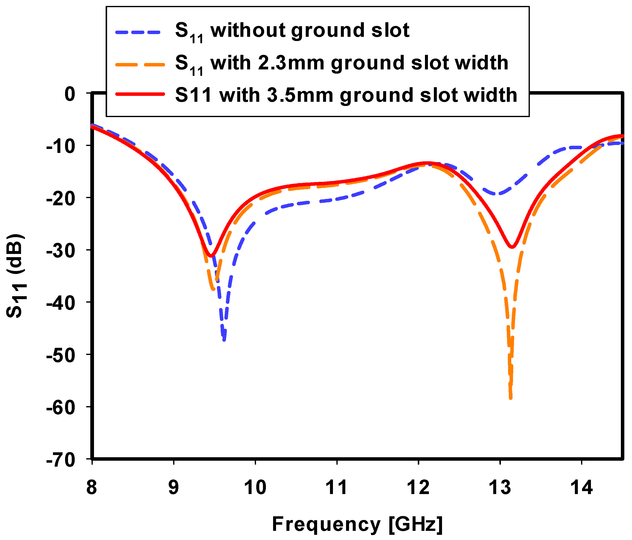
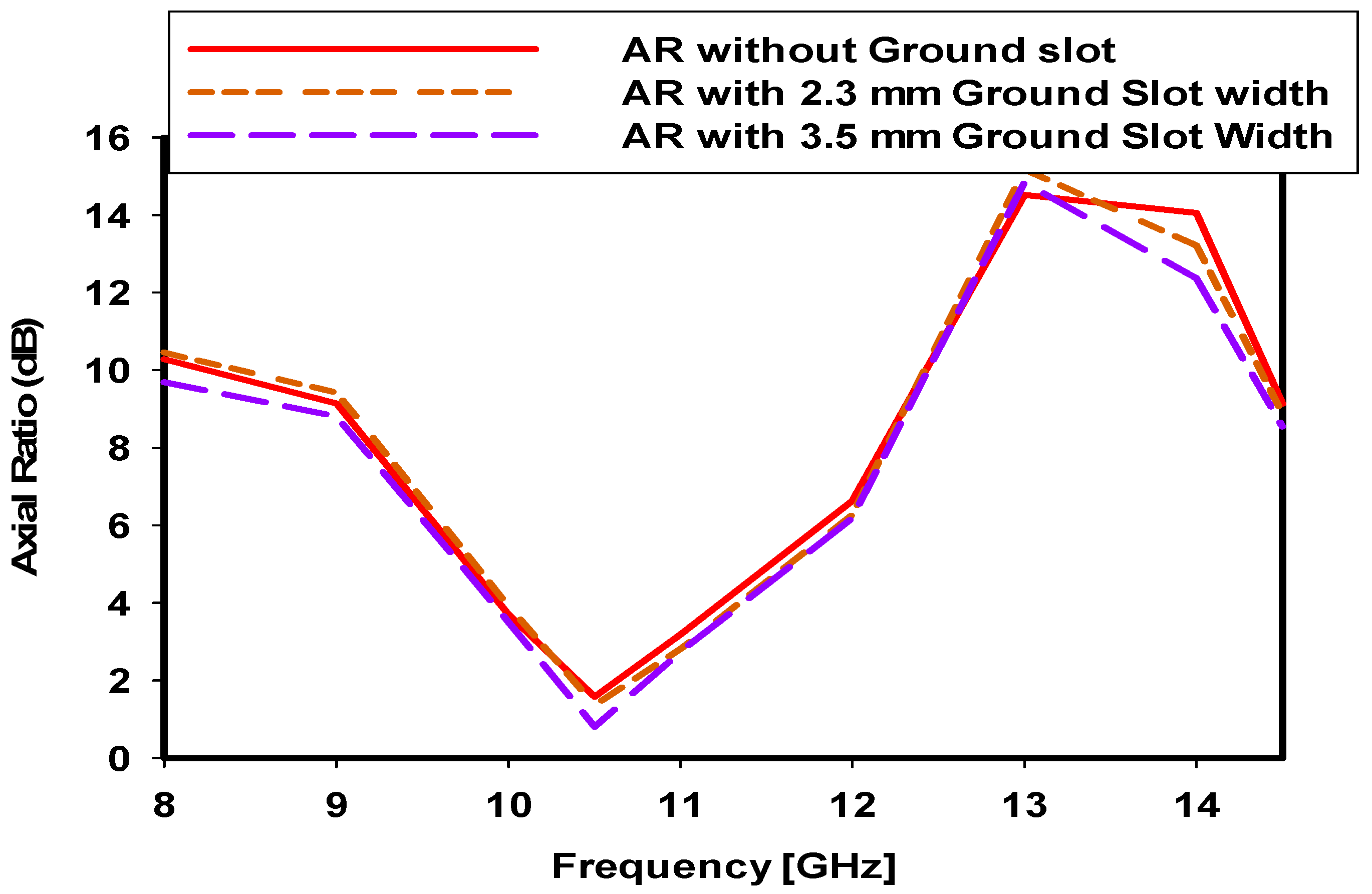
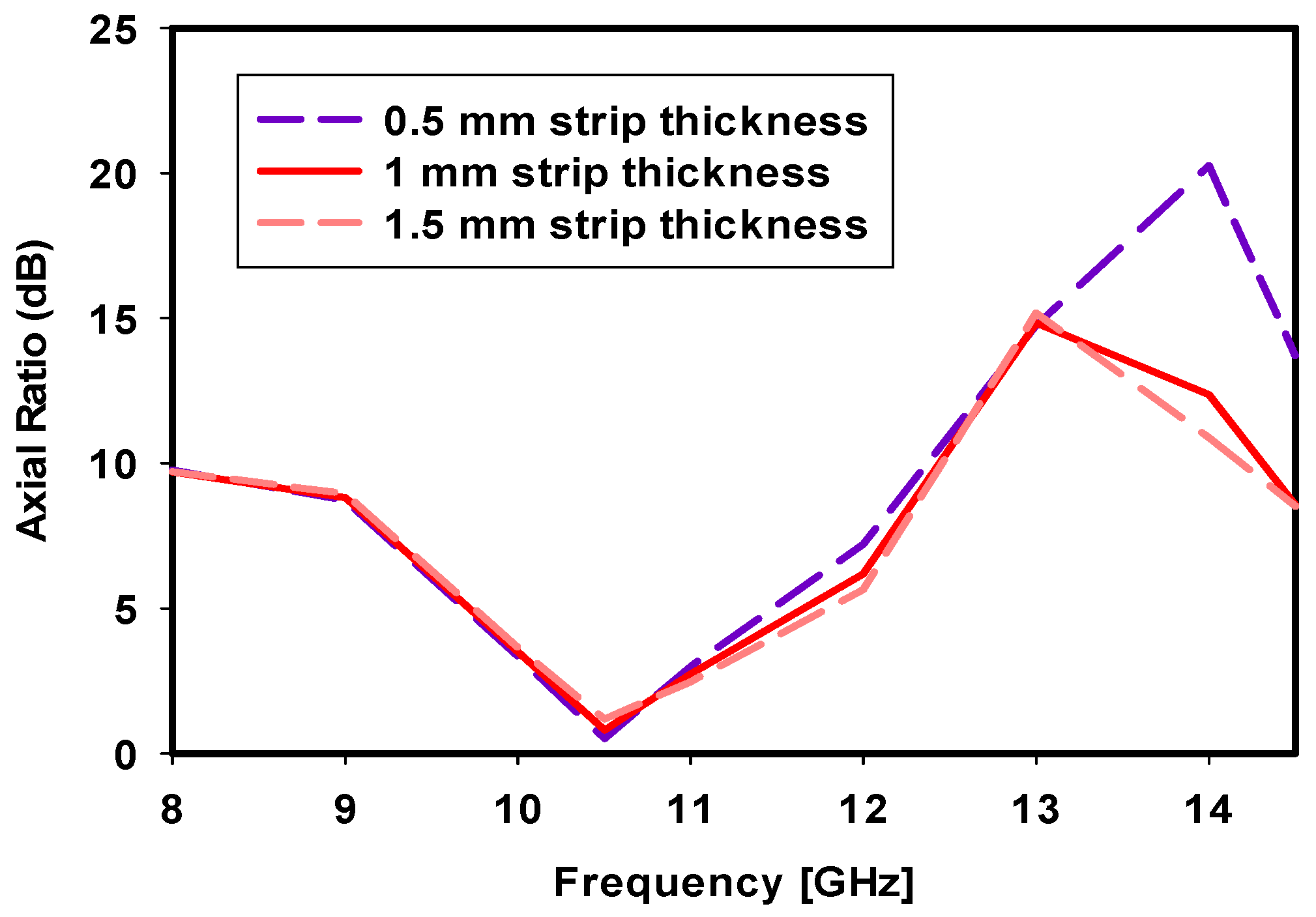
This section consists of the steps for the design of the wideband CP DRA. The design is finalized in five steps and each step is discussed in detail. The proposed antenna design is simulated by using CST Microwave Studio 2019 version, which is using Finite Element Method (FEM) numerical technique. Figure 2 shows all the steps which help to get the final design and results. Figure 3 and Figure 4 depict the corresponding simulated results which are achieved because of the different design steps. Initially the DR is excited by stationing the coaxial probe at the midpoint of the XZ side of the DR. The simulated results from Figure 3 and Figure 4 show that the design resonates at 14 GHz with no CP performance. In the next step, the feeding position of the DR is changed. The DR is excited with corner feeding. This arrangement generates two wide operating bands with relatively good impedance matching. With this step, the design is also circularly polarized; however, CP performance needs more improvement. In the next step, a cylindrical air gap is introduced at the center of the DR. This improves the impedance matching of both the resonance frequencies. However, introduction of the air gap does not largely affect the axial ratio. To cover the operating band from 8.5 GHz to 14.5 GHz a rectangular slot is carved on the ground. This highly improves the impedance matching of the whole operating band. At this stage, the design has a wideband response from 8.5 GHz to 14.5 GHz. However, this step does not change the axial ratio bandwidth. In the final step, a copper strip is stacked on the top of the DR. This improves the axial ratio and enhances the axial ratio bandwidth to 1 GHz.

4. Parametric Study

From the design, it is clear that the suggested wideband circularly polarized DRA is finalized in multiple steps. Thus, the final design depends on several parameters which affect the simulated results. These parameters include an air gap in the middle of the DR, a rectangular slot at the ground and a copper strip at the top of the DR. Some of these parameters effect both the reflection coefficient and axial ratio, while others affect either reflection coefficient or axial ratio alone.
The first parametric analysis is performed for the air gap. Variations in the radius of the air gap change the reflection coefficients and impedance matching accordingly, while it has no significant effect on the axial ratios. Results of the air gap impact on the return loss is given in Figure 5. As evident in Figure 5, it can be clearly observed that increasing the air gap shifts the operating band to the right (higher range). The impedance matching of the operating band improves with the introduction of the air gap in the center of the DR. Thus, an air gap effects both the operating band and impedance matching. Based on the final simulated values, an air gap of 1.5 mm radius is finally selected.
Another important parameter is the ground slot. The effect of the ground slot on the reflection coefficient and axial ratio is illustrated in Figure 6 and Figure 7, respectively. Figure 6 shows that in the absence of the ground slot the operating band is narrow and with relatively poor impedance matching at higher frequencies. Adding a ground slot with 2.3 mm slot width improves both the operating bandwidth and impedance matching. Further increase in the slot width slightly reduces the impedance matching. It is pertinent to mention that the variation in the ground slot width also slightly effects the axial ratio. Figure 7 shows this variation in detail. In the absence of the ground slot, the design is circularly polarized with poor axial ratio performance and axial ratio bandwidth. Adding the ground slot with 2.3 mm width improves both the axial ratio performance and axial ratio bandwidth. Increasing it further, the ground slot width further improves the axial ratio performance and axial ratio bandwidth. However, Figure 6 shows that at 3.5 mm width of the ground slot the impedance matching is decreased, but it is still considered a good value. Thus, at 3.5 mm width of the ground slot, the design has a good axial ratio bandwidth and performance with good operating band and impedance matching.
Another important parameter is the stacked strip on the top of the DR. This important parameter mainly effects the axial ratio of the design while it has minimum effect on the reflection coefficient. Figure 8 depicts the effect of the increase or decrease in the copper strip length on the axial ratio. At 0.5 mm length of the strip, the axial ratio performance is better, but the axial ratio bandwidth is narrow. Slightly increasing the copper strip length to 1 mm slightly decreases the axial ratio performance but increases the axial ratio bandwidth. Any more increase in the strip length further reduces the axial ratio bandwidth but enhances the axial ratio performance. Any further increase in the strip width does not enhance the axial ratio bandwidth, while a degradation in axial ratio performance is noticed and therefore 1.5 mm length of the strip is finalized for the final design.
The circular polarization characteristics of the proposed design are explained with the help of the electric field distribution on the top surface of the DR, which is shown in Figure 9. The corner feeding mechanism and the copper strip on the top of the DR collectively generate orthogonal modes in the DR. The electric field distribution of the proposed design is shown at 10.5 GHz. The electric field distribution confirms the phase change at 0° and 90°, respectively. It is observed that the corner feeding mechanism with the DR change the current distribution in the DR and CP mode is generated. The electric field distribution at 0° and 90° shows a counterclockwise rotation of the electric field, therefore the proposed design is right hand circularly polarized (RHCP).

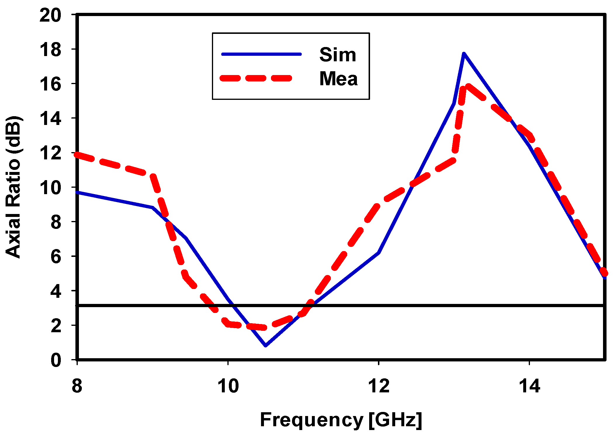
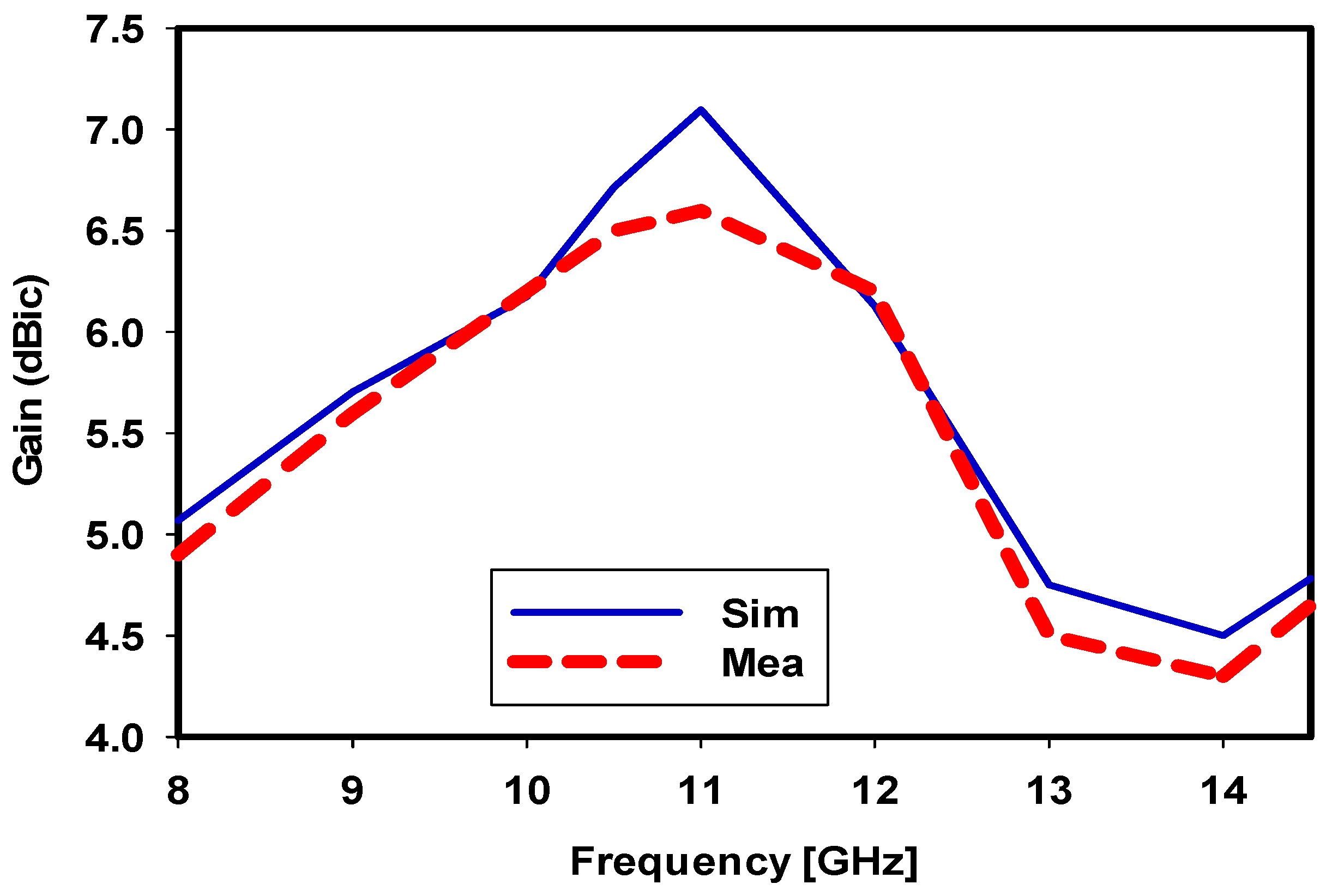
5. Final Simulated and Measured Results

The simulated results of the proposed model are varified with the help of the fabricated design. As shown in fabricated design, the rectangular slot is carved on the ground plane. The DR is positioned on the Roger substrate. A copper strip is piled on the top surface of the DR. Meanwhile the coaxial probe is used to excite the DR from the edge. The reflection coefficient of the design is assesed with the help of the Vector Network Analyser (VNA). The simulated and measured reflection coefficient of the design is depicted in Figure 10. For −10 dB reference value of the reflection coeffcient, the simulated operating bandwidth of the design is from 8.45 GHz to 14.09 GHz. The simulated resonance frequencies are 9.44 GHz and 13.13 GHz, respectively. The measured reflection coefficient follows the simulated values. The measured operating band starts from 8.58 GHz and ends on 14.09 GHz. The measured resonance frequncies are the same with better impedance matching. Figure 11 depicts the simulated and measured axial ratios of the design. For 3 dB reference value, the simulated axial ratio bandwidth is from 10.085 GHz to 11.10 GHz. The max dip of the axial ratio is at 10.5 GHz. Measured axial ratio bandwidth is slightly right shifted, and ranges from 9.8 GHz to 10.8 GHz. This shift and slight degredation in axial ratio performance is due to fabrication inaccuracies and surrounding noise in the chamber.
The proposed design has a good, measured gain, efficiency and radiation pattern. All the measured values are close to the simulated values. The measured peak gain of the design is shown in Figure 12. The measured peak gain of the design is 6.5 dBic, i.e. is less than the simulated value. The measured gain of the design over the axial ratio bandwidth is between 6 to 6.5 dBic. The minor deviation in the measured values is due to imperfect fabrication of the prototype. Figure 13 illustrate the simulated and measured radiation efficiencies of the design. Their values over the entire axial ratio bandwidth are more than 96%. Figure 14 depicts the simulated and measured RH (Right Hand) CP and LH (Left Hand) CP far field patterns at 10.5 GHz central frequency of the AR. The electric fields distribution on the DR top surface show that the design is dominantly RHCP by 37 dB in the main direction of the radiation. The direction of radiation at 10.5 GHz is boresight and focused towards 15°. The radiation pattern of the design in terms of E-field and H-field at 9.44 GHz and 13.13 GHz is depicted in Figure 15 and Figure 16, respectively. The radiation pattern at 9.44 GHz is broadside with 6.5 dBic radiation gain. Both the simulated and measured radiation pattern at 9.44 GHz are quite close to each other. At 13.13 GHz, the main radiation lobe is now focused at 330° with a relatively narrow beam width. The design has a good radiation gain of more than 5 dBic. The simulated and measured radiation pattern gain at 13.13 GHz are also in close matching. Figure 17a,b show the top and bottom views of the fabricated design while c shows the radiation pattern measurement setup.
A comparison of the proposed design with the recently published work is presented in Table 2. From the Table 2 it is clear that the proposed design in comparison with the published work is very simple with good gain, very high efficiency, simple architecture and compact size. Column 1 of Table 2 shows that the proposed design has size comparison both in physical lengths and electrical lengths. Our design is compact both in physical and electrical lengths. Moreover, the design has a very wide band with a good CP performance. All these parameters and results confirm the novelty of the design. Based on the results, the proposed design is a good candidate for the RADAR and satellite wireless application.

6. Conclusions

A very compact wideband circularly polarized DRA has been proposed in this work. The operating bandwidth is enhanced with a rectangular slot in the ground. The CP performance is achieved with an edge feeding of the DR by a coaxial probe. The axial ratio performance is enhanced with a copper strip on the top of the DR. The achieved operating band is 59.74% with 9.4% CP performance. The design has attained a good gain and a very high radiation efficiency. The fabricated design results are in close agreement with the simulated values, which makes the design a good candidate for X-band wireless application.

Author Contributions

Conceptualization, S.K., R.M.G. and M.A.K.; methodology, S.K. and M.A.; software, S.N.K.M. and N.J.; validation, M.A. and M.A.K.; formal analysis, S.N.K.M. and R.M.G.; investigation, N.J.; resources, M.A. and N.J.; data curation, S.N.K.M. and M.A.K.; writing—original DRAft preparation, S.K., R.M.G. and M.A.K.; writing—review and editing, R.M.G.; visualization, M.A.; supervision, S.K. and M.A.K.; project administration, S.K.; funding acquisition, R.M.G. All authors have read and agreed to the published version of the manuscript.

Funding

Princess Nourah bint Abdulrahman University Researchers Supporting Project number (PNURSP2022R138), Princess Nourah bint Abdulrahman University, Riyadh, Saudi Arabia.

Data Availability Statement

All Data have been included in study.

Acknowledgments

The authors appreciate the support from Princess Nourah bint Abdulrahman University Researchers Supporting Project number (PNURSP2022R138), Princess Nourah bint Abdulrahman University, Riyadh, Saudi Arabia.

Conflicts of Interest

The authors declare no conflict of interest.

References

  1. Counselman, C.C. Multipath-rejecting GPS antennas. Proc. IEEE 1999, 87, 86–91. [Google Scholar] [CrossRef]
  2. Banerjee, U.; Karmakar, A.; Saha, A. A review on circularly polarized antennas, trends and advances. Int. J. Microw. Wirel. Technol. 2020, 12, 922–943. [Google Scholar] [CrossRef]
  3. Kumar, R.; Chaudhary, R.K. Stacked rectangular dielectric resonator antenna with different volumes for wideband circular polarization coupled with step-shaped conformal strip. Int. J. RF Microw. Comput.-Aided Eng. 2019, 29, e21667. [Google Scholar] [CrossRef]
  4. Kumar, R.; Chaudhary, R.K. A wideband circularly polarized cubic dielectric resonator antenna excited with modified microstrip feed. IEEE Antennas Wirel. Propag. Lett. 2015, 15, 1285–1288. [Google Scholar] [CrossRef]
  5. Petosa, A. Dielectric Resonator Antenna Handbook; Artech: Morristown, NJ, USA, 2007. [Google Scholar]
  6. Mongia, R.K.; Bhartia, P. Dielectric resonator antennas—A review and general design relations for resonant frequency and bandwidth. Int. J. Microw. Millim. -Wave Comput. -Aided Eng. 1994, 4, 230–247. [Google Scholar] [CrossRef]
  7. Khattak, M.A.; Khattak, M.I.; Owais, S.M.; Khattak, A.A.; Sultan, A. Design and analysis of millimeter wave dielectric resonator antenna for 5G wireless communication systems. Prog. Electromagn. Res. C 2020, 98, 239–255. [Google Scholar]
  8. Petosa, A.; Ittipiboon, A. Dielectric resonator antennas: A historical review and the current state of the art. IEEE Antennas Propag. Mag. 2010, 52, 91–116. [Google Scholar] [CrossRef]
  9. Leung, K.W.; Lim, E.H.; Fang, X.S. Dielectric resonator antennas: From the basic to the aesthetic. Proc. IEEE 2012, 100, 2181–2193. [Google Scholar] [CrossRef]
  10. Meher, P.R.; Behera, B.R.; Mishra, S.K. Design and its state-of-the-art of different shaped dielectric resonator antennas at millimeter-wave frequency band. Int. J. RF Microw. Comput. -Aided Eng. 2020, 30, e22221. [Google Scholar] [CrossRef]
  11. Dash, S.K.K.; Khan, T.; De, A. Dielectric resonator antennas: An application oriented survey. Int. J. RF Microw. Comput. -Aided Eng. 2017, 27, e21069. [Google Scholar] [CrossRef]
  12. Meher, P.R.; Behera, B.R.; Mishra, S.K.; Althuwayb, A.A. A chronological review of circularly polarized dielectric resonator antenna: Design and developments. Int. J. RF Microw. Comput. -Aided Eng. 2021, 31, e22589. [Google Scholar] [CrossRef]
  13. Balanis, C.A. Antenna Theory, 3rd ed.; Wiley: Hoboken, NJ, USA, 2005. [Google Scholar]
  14. Lukand, K.M.; Leung, K.W. Dielectric Resonator Antennas; Research Studies: Baldock, UK, 2003. [Google Scholar]
  15. Zou, M.; Pan, J.; Nie, Z. A wideband circularly polarized rectangular dielectric resonator antenna excited by an archimedean spiral slot. IEEE Antennas Wirel. Propag. Lett. 2014, 14, 446–449. [Google Scholar] [CrossRef]
  16. Wang, K.X.; Wong, H. A circularly polarized antenna by using rotated-stair dielectric resonator. IEEE Antennas Wirel. Propag. Lett. 2014, 14, 787–790. [Google Scholar] [CrossRef]
  17. Zou, M.; Pan, J. Wideband hybrid circularly polarised rectangular dielectric resonator antenna excited by modified cross-slot. Electron. Lett. 2014, 50, 1123–1125. [Google Scholar] [CrossRef]
  18. Pan, Y.; Leung, K.W. Wideband circularly polarized trapezoidal dielectric resonator antenna. IEEE Antennas Wirel. Propag. Lett. 2010, 9, 588–591. [Google Scholar] [CrossRef]
  19. Varshney, G.; Pandey, V.S.; Yaduvanshi, R.S.; Kumar, L. Wide band circularly polarized dielectric resonator antenna with stair-shaped slot excitation. IEEE Trans. Antennas Propag. 2016, 65, 1380–1383. [Google Scholar] [CrossRef]
  20. Fakhte, S.; Oraizi, H.; Karimian, R.; Fakhte, R. A new wideband circularly polarized stair-shaped dielectric resonator antenna. IEEE Trans. Antennas Propag. 2015, 63, 1828–1832. [Google Scholar] [CrossRef]
  21. Lu, L.; Jiao, Y.C.; Zhang, H.; Wang, R.; Li, T. Wideband circularly polarized antenna with stair-shaped dielectric resonator and open-ended slot ground. IEEE Antennas Wirel. Propag. Lett. 2016, 15, 1755–1758. [Google Scholar] [CrossRef]
  22. Patel, P.; Mukherjee, B.; Mukherjee, J. Wideband circularly polarized rectangular dielectric resonator antennas using square-shaped slots. IEEE Antennas Wirel. Propag. Lett. 2015, 15, 1309–1312. [Google Scholar] [CrossRef]
  23. Varshney, G. Gain and bandwidth enhancement of a singly-fed circularly polarised dielectric resonator antenna. IET Microw. Antennas Propag. 2020, 14, 1323–1330. [Google Scholar] [CrossRef]
  24. Sun, Y.X.; Leung, K.W.; Mao, J.F. Dual function dielectric resonator as antenna and phase-delay-line load: Designs of compact circularly polarized/differential antennas. IEEE Trans. Antennas Propag. 2017, 66, 414–419. [Google Scholar] [CrossRef]
  25. Podilchak, S.K.; Johnstone, J.C.; Caillet, M.; Clénet, M.; Antar, Y.M. A compact wideband dielectric resonator antenna with a meandered slot ring and cavity backing. IEEE Antennas Wirel. Propag. Lett. 2015, 15, 909–913. [Google Scholar] [CrossRef]
  26. Chair, R.; Yang, S.L.S.; Kishk, A.A.; Lee, K.F.; Luk, K.M. Aperture fed wideband circularly polarized rectangular stair shaped dielectric resonator antenna. IEEE Trans. Antennas Propag. 2006, 54, 1350–1352. [Google Scholar] [CrossRef]
  27. Fakhte, S.; Oraizi, H.; Karimian, R. A novel low-cost circularly polarized rotated stacked dielectric resonator antenna. IEEE Antennas Wirel. Propag. Lett. 2014, 13, 722–725. [Google Scholar] [CrossRef]
  28. Altaf, A.; Yang, Y.; Lee, K.Y.; Hwang, K.C. Circularly polarized Spidron fractal dielectric resonator antenna. IEEE Antennas Wirel. Propag. Lett. 2015, 14, 1806–1809. [Google Scholar] [CrossRef]
  29. Yadav, S.K.; Kaur, A.; Khanna, R. Broadband circularly polarized dielectric resonator antenna for UWB applications. Sādhanā 2022, 47, 1–8. [Google Scholar] [CrossRef]
  30. Elahi, M.; Altaf, A.; Yang, Y.; Lee, K.Y.; Hwang, K.C. Circularly polarized dielectric resonator antenna with two annular vias. IEEE Access. 2021, 9, 41123–41128. [Google Scholar] [CrossRef]
  31. Khan, S.; Ali, H.; Khalily, M.; Shah SU, A.; Kazim JU, R.; Ali, H.; Tanougast, C. Miniaturization of Dielectric Resonator Antenna by Using Artificial Magnetic Conductor Surface. IEEE Access. 2020, 8, 68548–68558. [Google Scholar] [CrossRef]
  32. Chakraborty, P.; Banerjee, U.; Saha, A.; Karmakar, A. A compact ultra wideband dielectric resonator antenna with dual-band circular polarization characteristics. Int. J. RF Microw. Comput. -Aided Eng. 2021, 31, e22577. [Google Scholar] [CrossRef]
  33. Yang, W.W.; Sun, W.J.; Tang, H.; Chen, J.X. Design of a circularly polarized dielectric resonator antenna with wide bandwidth and low axial ratio values. IEEE Trans. Antennas Propag. 2019, 67, 1963–1968. [Google Scholar] [CrossRef]
  34. Kumar, R.; Thummaluru, S.R.; Chaudhary, R.K. Improvements in Wi-MAX reception: A new dual-mode wideband circularly polarized dielectric resonator antenna. IEEE Antennas Propag. Mag. 2019, 61, 41–49. [Google Scholar] [CrossRef]
  35. Kumar, R.; Chaudhary, R.K. A New Bidirectional Wideband Circularly Polarized Cylindrical Dielectric Resonator Antenna using Modified J-shaped Ground Plane for WiMAX/LTE Applications. Radioengineering 2019, 28, 391–398. [Google Scholar] [CrossRef]
  36. Varshney, G.; Pandey, V.S.; Yaduvanshi, R.S. Axial ratio bandwidth enhancement of a circularly polarized rectangular dielectric resonator antenna. Int. J. Microw. Wirel. Technol. 2018, 10, 984–990. [Google Scholar] [CrossRef]
  37. Kumari, R.; Gangwar, R.K. Circularly polarized slot-coupled square dielectric resonator antenna for WLAN applications. Microw. Opt. Technol. Lett. 2018, 60, 2787–2794. [Google Scholar] [CrossRef]
  38. Kumar, R.; Nasimuddin, N.; Chaudhary, R.K. A new dual C-shaped rectangular dielectric resonator based antenna for wideband circularly polarized radiation. Int. J. RF Microw. Comput. -Aided Eng. 2019, 29, e21672. [Google Scholar] [CrossRef]
  39. Varshney, G.; Gotra, S.; Pandey, V.S.; Yaduvanshi, R.S. Inverted-sigmoid shaped multiband dielectric resonator antenna with dual-band circular polarization. IEEE Trans. Antennas Propag. 2018, 66, 2067–2072. [Google Scholar] [CrossRef]
  40. Dash, S.K.K.; Khan, T.; Kanaujia, B.K. Circularly polarized dual facet spiral fed compact triangular dielectric resonator antenna for sensing applications. IEEE Sens. Lett. 2018, 2, 1–4. [Google Scholar] [CrossRef]
  41. Chowdhury, R.; Chaudhary, R.K. An approach to generate circular polarization in a modified cylindrical-shaped dielectric resonator antenna using PMC boundary approximation. IEEE Antennas Wirel. Propag. Lett. 2018, 17, 1727–1731. [Google Scholar] [CrossRef]
  42. Chowdhury, R.; Mishra, N.; Sani MMand Chaudhary, R.K. Analysis of a wideband circularly polarized cylindrical dielectric resonator antenna with broadside radiation coupled with simple microstrip feeding. IEEE Access 2017, 5, 19478–19485. [Google Scholar] [CrossRef]
  43. Gupta, A.; Gangwar, R.K. Dual-band circularly polarized aperture coupled rectangular dielectric resonator antenna for wireless applications. IEEE Access 2018, 6, 11388–11396. [Google Scholar] [CrossRef]
Figure 1. (a) Shows the top view of the proposed design, (b) shows the bottom view of the design while, (c) shows the side view of the design.
Electronics 11 03281 g001
Figure 2. Design steps of the proposed antenna.
Electronics 11 03281 g002
Figure 3. Reflection coefficients for the different steps of the proposed design.
Electronics 11 03281 g003
Figure 4. Axial ratios of the proposed design for the different design steps.
Electronics 11 03281 g004
Figure 5. Effect of changing the air gap radius on the Reflection Coefficient.
Electronics 11 03281 g005
Figure 6. Effect of variation in the ground slot on the reflection coefficient.
Electronics 11 03281 g006
Figure 7. Effect of variation in the ground slot on the Axial Ratio.
Electronics 11 03281 g007
Figure 8. Effect of variation in the copper strip on the axial ratio.
Electronics 11 03281 g008
Figure 9. Electric field distribution on the top surface of the DR at (a) T = 0, and (b) T = t/4.
Electronics 11 03281 g009
Figure 10. Simulated and measured reflection coefficients of the proposed design.
Electronics 11 03281 g010
Figure 11. Simulated and measured axial ratios of the design.
Electronics 11 03281 g011
Figure 12. Simulated and measured realized gain of the design.
Electronics 11 03281 g012
Figure 13. Simulated and measured radiation efficiencies of the design.
Electronics 11 03281 g013
Figure 14. Simulated and measured far field patterns at 10.5 GHz in (a) ϕ = 0°, (b) ϕ = 90°.
Electronics 11 03281 g014
Figure 15. Simulated and measured radiation patterns at 9.44 GHz in (a) XY plane (E-field), and (b) YZ plane (H-field) of the proposed design.
Electronics 11 03281 g015
Figure 16. Simulated and measured radiation pattern at 13.13 GHz in (a) XY plane (E-field), and (b) YZ plane (H-field) of the proposed design.
Electronics 11 03281 g016
Figure 17. Fabricated prototype: (a) top view, (b) bottom view, (c) measurement setup in anechoic chamber.
Electronics 11 03281 g017
Table 1. Dimension table of the proposed design.
ParametersSize (mm)ParametersSize (mm)
Wsub14Wgrd14
Lsub21Lgrd21
WDRA9.2Wslot7.5
LDRA4.9Lslot3.7
Top Patch Length 1.5hDRA5.12
Table 2. Comparison of the proposed design with the state-of-the-art published work.
Size (mm3)/λ3BW (GHz)AR BW
(GHz)
AR BW
(%)
GainMax. Eff.
(%)
Ref.
90 × 90 × 15/1.88 × 1.88 × 0.310.250.255.56–7 dBic96[30]
63 × 75 × 6.1/1.05 × 1.25 × 0.1010.90.717.28,
11.56
7 dBi83[32]
23 × 23 × 2/1.64 × 1.64 × 0.1432.5276.5 dB--[33]
40 × 40 × 18/0.94 × 0.94 × 0.4210.417.54.2 dBic87[34]
40 × 32 × 14/1.04 × 0.83 × 0.361.51.129.92.8 dBic94[35]
80 × 80 × 5/2.65 × 2.65 × 0.164.13.356.62.7 dBic80[36]
44 × 45 × 11/2.65 × 2.65 × 0.160.50.17.944 dB95[37]
45 × 40 × 15/1.15 × 1.02 × 0.380.90.412.35.2 dBic88[38]
50 × 50 × 5/2.08 × 2.08 × 0.203, 1.11.3,
0.3
19.34,
3.15
4.38 dBi,
6.4 dBi
80[39]
50 × 50 × 10/3.95 × 3.95 × 0.790.4, 1.10.2,
0.2
1.6,
1.8
2.2 dBi,
3.7 dBi
90[40]
50 × 50 × 16/1.29 × 1.29 × 0.412.00.37.75 dBic--[41]
55 × 55 × 23/1.14 × 1.14 × 0.471.00.823.75.5 dBi96[42]
40 × 40 × 8/0.97 × 0.97 × 0.191.1, 0.90.02,
0.37
1.03,
3.4
5.3 dBi,
5.7 dBi
93, 96[43]
14 × 21 × 5.1/0.66 × 1.00 × 0.245.641.19.56.5 dBic95.5This Work
Publisher’s Note: MDPI stays neutral with regard to jurisdictional claims in published maps and institutional affiliations.

