Article

FPGA in the Loop Implementation for Observer Sliding Mode Control of DFIG-Generators for Wind Turbines

1
Faculty of Sciences Dhar El Mahraz, Sidi Mohammed Ben Abdellah University, Fez 30000, Morocco
2
Engineering, Systems, and Applications Laboratory, ENSA, Sidi Mohammed Ben Abdellah University, Fez 30000, Morocco
3
Department of Computer Science, College of Computers and Information Technology, Taif University, P.O. Box 11099, Taif 21944, Saudi Arabia
4
Laboratory of Renewable Energy and Dynamic of Systems, University Hassan II Faculty of Sciences Ain-Cock, Casablanca 40000, Morocco
*
Authors to whom correspondence should be addressed.
Electronics 2022, 11(1), 116; https://doi.org/10.3390/electronics11010116
Submission received: 3 November 2021 / Revised: 22 December 2021 / Accepted: 28 December 2021 / Published: 30 December 2021

Abstract

:
This paper presents a new contribution of the nonlinear control technique of electrical energy in a wind energy system. The nonlinear sliding mode technique used to control the powers of the DFIG-Generator is connected to the power grid by two converters (grid side and machine side). The proposed model is validated using tracking and robustness tests with a real wind speed. The control was developed under Matlab/Simulink, and the FPGA in the Loop technique was used to design the DFIG model. By employing a co-simulation, the purpose is to test the controller for the FPGA simulated model or system in its entirety. The results obtained by the cο-simulation show the efficiency of the proposed model in terms of speed and robustness with a rate THD = 0.95, and the proposed model of the sliding mode controller shows a significant improvement in the quality of energy produced by the wind system.

1. Introduction

In the last three decades, renewable energy sources have garnered considerable interest. Due to technological developments, cost reductions, and rising demand, they have become a realistic option, particularly in developing nations. However, reconfiguring the power system network will necessitate a significant transition away from conventional to renewable energy-based energy production due to its limited nature, environmental effect, and sustainability, as well as the global annual increase in energy consumption [1].
The wind is the most environmentally friendly, dependable, cost-effective, and adaptable renewable energy source for power producers to integrate into electrical grids [2]. Due to its compact size and low cost, high efficiency, long-term operation, low acoustic noise, wide operating range, and flexibility in four-quadrant active and reactive power regulation, DFIG is widely employed in current variable-speed WECS for wind energy production [3].
The control system is designed to ensure that the DFIG’s terminal voltage and frequency remain constant regardless of wind speed changes or auxiliary load. However, creating a control system for grid-integrated WECS is a significant task due to the unpredictable nature of wind speed [4]. In addition, it evaluates the wind energy system’s overall efficiency and adds to the structural stability of the power converters [5]. As a result, considerable research has been conducted to improve the performance of control loops.
While classic controllers based on linear proportional integral (PI) perform admirably in a wide variety of control applications, they have severe limitations, including machine parameter variations [6,7]. Throughout the decades, numerous unique control strategies have been proposed to replace the standard control strategy in order to improve accuracy and precision performance. Backstepping control [8,9], intelligent control [10,11], model predictive control [12,13], and sliding mode control [14,15] are all examples of these controllers.
The conventional sliding mode method produces an undesired chattering effect that might be detrimental to the system. Thus, it is appropriate to investigate sliding mode algorithms that inherit all of the SMC’s features and attenuate chattering phenomena in a regulated manner [16,17,18].
The purpose of this article is to describe the application of an upgraded sliding mode adaptive nonlinear control to a WECS-DFIG that is controlled by power converters (grid and generator sides). Additionally, the primary purpose is to prevent chattering and improve the performance of wind systems operating under changeable wind reference conditions. Our contribution to this work is to guarantee and improve the operation of a wind energy system using a nonlinear model and a nonlinear control technique and increase the system’s performance using an optimized model of the sliding mode.
In this work, an implementation on the FPGA target of our control model has been developed. The main objective is to develop and validate the model controller validated in simulation (Matlab and Simulink). The FPGA in the Loop (HILS) simulation technique is a real-time simulation technique with the use of I/O from the board that allows us to test and verify the operation of the system under different loads and conditions.
After the Section 1, Section 2 is dedicated to modeling of the system (WECS), Section 3 discusses the basic principle and the design procedure of the proposed sliding mode technique control. In Section 4, the co-simulation results of the proposed control are presented, analyzed, and then compared with other controls results. The last section of this paper is devoted to a brief conclusion.

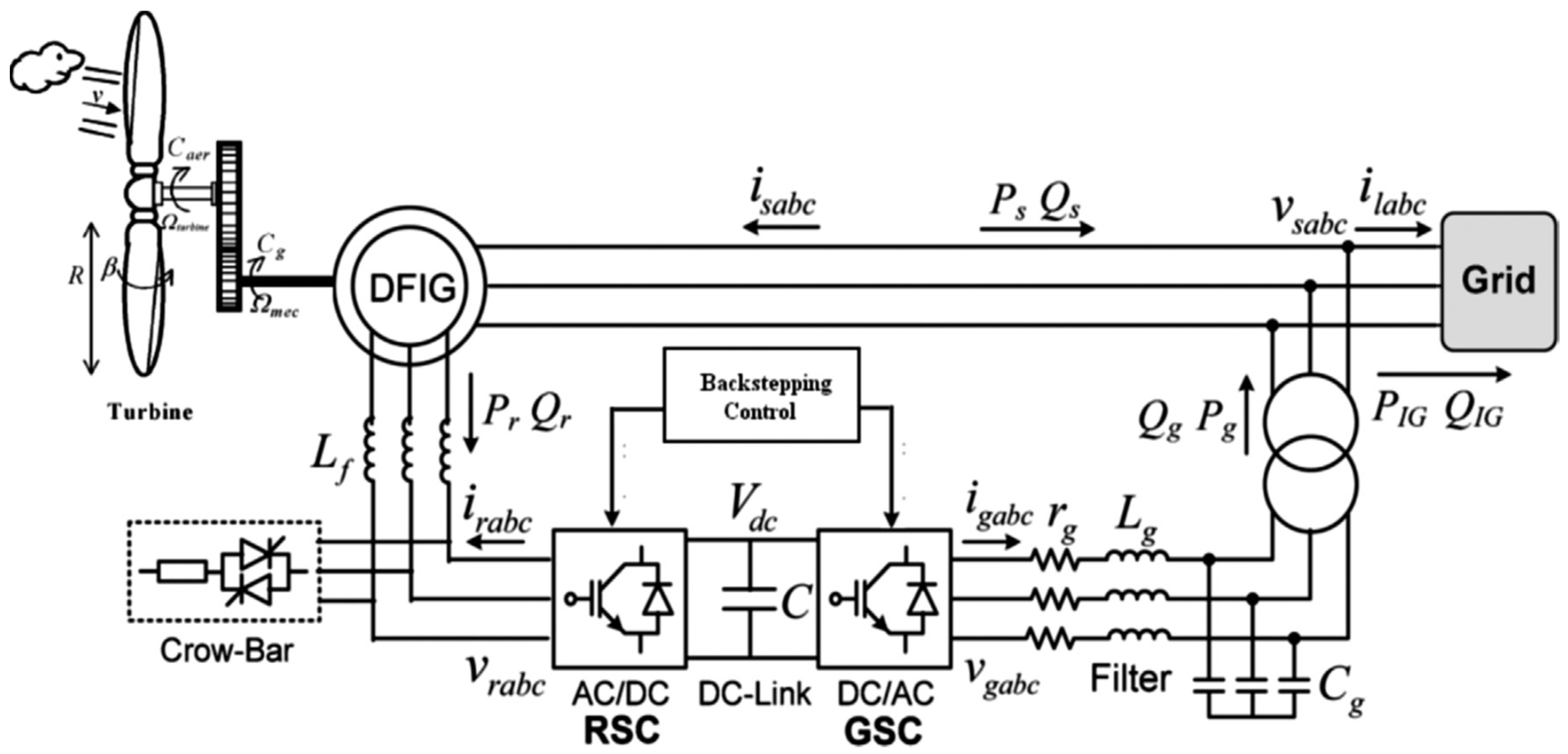
2. Presentation of the Wind Turbine Conversion Chain

The wind turbine conversion chain is composed of a wind turbine consisting of three blades, fixed on a drive shaft, which is connected to a gearbox, a DFIG generator, inverter mode (RSC), and the other mode (GSC) presented in Figure 1 [19].
  • Wind Turbine Model
The authors of [21] have carefully described the process of a wind turbine, and the following equations briefly describe its model:
{ P aero = 1 2 · C p max ( λ , β ) · ρ · π · R 2 · v 3 λ = R · Ω t v C p Max = 16 27 = 0.5925 C p ( λ , β ) = C 1 ( C 2 A C 3 · β C 4 ) e C 5 A + C 6
The parameters “C1…C6” are constant depending on the geometry of the wind turbine.
  • Gearbox Model
{ Ω t = Ω mec G C g = C aero G
  • The Mechanichal Shaft Models
The proposed mechanical model is characterized by the following equations [22,23,24,25]:
J tot = J t G 2 + J g C mec = J tot · d Ω mec dt = C g C em C f
With:
C f = f · Ω mec
  • DFIG Mode after Park Transformation
Applying the Park transformation on the DFIG-Generator, we get the following equations:
{ v sd = R s · I sd + d Φ sd dt ω s · Φ sq v sq = R s · I sq + d Φ sq dt + ω s · Φ sd v rd = R r · I rd + d Φ rd dt ω r · Φ rq v rq = R r · I rq + d Φ rq dt ω r · Φ rd Φ sd = L s · I sd + M · I rd Φ sq = L s · I sq + M · I rq Φ rd = L r · I rd + M · I sd Φ rq = L r · I rq + M · I sq P s = v sd · I sd + v sq · I sq Q s = v sq · I sd + v sd · I sq P r = v rd · I rd + v rq · I rq Q r = v rq · I rd + v rd · I rq
  • Converters Model
The DC-Bus in Figure 1 illustrates the structure [22,26,27].
The following equations characterize the continuous bus:
{ W dc = P c · d t = 1 2 · C · V dc 2 d V dc 2 dt = 2 C ( P f P r )
  • Filter (RL) Model
The filter model in the park reference is:
{ v df = R f · I df L f · dI df dt + ω s · L f · I qf v qf = R f · I qf L f · dI qf dt ω s · L f · I df + v s

3. Sliding Mode Control

The objective of the SMC control technique is to drive the path of the system state to reach the sliding surface for a period of time.
The evolution of a system subjected to a control rule is no longer determined by the system or external perturbations but by the sliding surface’s attributes. As a result, the system will be robust to uncertainty (system specific) and disruptions (system wide), as the control entirely rejects them.
Sliding mode control’s purpose is to synthesize a surface S(x,t) such that all system trajectories exhibit the appropriate tracking, control, and stability behavior. Additionally, the purpose is to determine a control rule (switching) U(x,t) capable of attracting and maintaining all state trajectories on the sliding surface.
Three complimentary processes comprise the design of the sliding mode control algorithm.
The choice of the sliding surface
Because the sliding surface is a scalar function, the error of the controlled variable slides along it and tends to the phase plane’s origin. As a result, the surface S(x) denotes the system’s desired dynamic behavior [28,29,30].
The sliding surface proposed is:
S ( x ) = ( d dt + δ ) r 1 × e ( x )
This control’s purpose is to keep the surface S(x) trending toward zero. The latter is a linear differential equation with a unique solution of e(x) = 0 when the parameter δ is chosen appropriately.
With the following:
δ : Positive gain that interprets the bandwidth of the desired control;
e(x): the deviation on the variable to be controlled e(x) = xd − x;
r: relative degree, the smallest positive integer representing the number of times it is necessary to derive to make the control appear.
The establishment of the existence condition
The existence and convergence conditions specify the conditions under which the system’s dynamics converge to the sliding surface and remain stationary in the presence of disturbances. One way of determining the stability of the sliding mode control is based on LYAPUNOV’s second theorem.
The determination of the control law
The control rule must be determined once the sliding surface and convergence criterion are specified. Its goal is to confine the system’s state trajectories to reach and then remain on the sliding surface notwithstanding the existence of uncertainty. In other words, the control law must be attractive to the sliding surface on a local level [31,32,33,34].

3.1. Control of the Converter on the DFIG RSC Side

For r = 1, the active and reactive power slip area is given by:
{ S ( P s ) = e 1 = P sref P s S ( Q s ) = e 2 = Q sref Q s
The following equation expresses the derivative of this surface:
{ S ( P ˙ s ) = e ˙ 1 = P ˙ sref P ˙ s S ( Q ˙ s ) = e ˙ 2 = Q ˙ sref Q ˙ s
With:
P ˙ s = v s · M L s I ˙ rq
Q ˙ s = v s 2 ω s · L s v s · M L s I ˙ rd
I ˙ rd = V rd L r · σ R r L r · σ · I rd + ω r · I rq
I ˙ rq = V rq L r · σ R r L r · σ · I rq ω r · I rd ω r · M · V s L r · L s · σ · ω s
The derivative of the sliding surface is given by:
{ e ˙ 1 = P ˙ sref + V s · M L s ( V rq L r · σ R r L r · σ I rq ω r I rd ω r V s M L r · L s · ω s · σ ) e ˙ 2 = Q ˙ sref + V s · M L s ( V rd L r · σ R r L r · σ I rd + ω r I rq )
{ e 1 , 2 = 0 e ˙ 1 , 2 = 0 V rdn = V rqn = 0
By replacing Equation (16) in Equation (15), the expression for the equivalent command V eq is as follows [14]:
{ V rdeq = L r · L s · σ M · V s Q ˙ sref + R r · I rd ω r · L r · σ · I rq V rqeq = L r · L s · σ M · V s P ˙ sref + R r · I rq + ω r · L r · σ · I rd + ω r V s M L s · ω s
The stabilizing control is [19]:
{ V rdn = K d · Sat ( e 1 ) V rqn = K q · Sat ( e 2 )
Hence, the expression for the total controls Vrd and Vrq is as follows:
{ V rd = L r · L s · σ M · V s · Q ˙ sref + R r · I rd ω r · L r · σ · I rq + K d Sat ( e 2 ) V rq = L r · L s · σ M · V s · P ˙ sref + R r · I rq + ω r · L r · σ · I rd + ω r · M · V s L s · ω s + K q Sat ( e 1 )

3.2. Control of the Converter on the GSC Grid Sid

We consider the sliding mode surface proposed by SLOTINE. For r = 1, we obtain the following equation [33,34,35]:
{ S ( P f ) = e 3 = P fref P f S ( Q f ) = e 4 = Q fref Q f
The following equation gives the derivative of the sliding surface [36]:
{ e ˙ 3 = P ˙ sref + V s · R f L f I qf + V s ( V qfeq + V qfn ) L f + ω s · V s · I df V s 2 L f e ˙ 4 = Q ˙ sref V s · R f L f I df V s ( V dfeq + V dfn ) L f + ω s · V s · I qf
With:
{ V dfeq = L f V s Q ˙ sref R f · I df + L f · ω s · I qf V qfeq = L f V s P ˙ sref R f · I qf L f · ω s · I df + V s
The following equation expresses the stabilizing control:
{ V dfn = K dfn · Sat ( e 4 ) V qfn = K qfn · Sat ( e 3 )
With:
{ V fd = L f V s · Q ˙ fref R f · I df + ω s · L f · I qf + K dfn Sat ( e 4 ) V fq = L f V s · P ˙ fref R f · I qf ω s · L f · I df + V s + K qfn Sat ( e 3 )

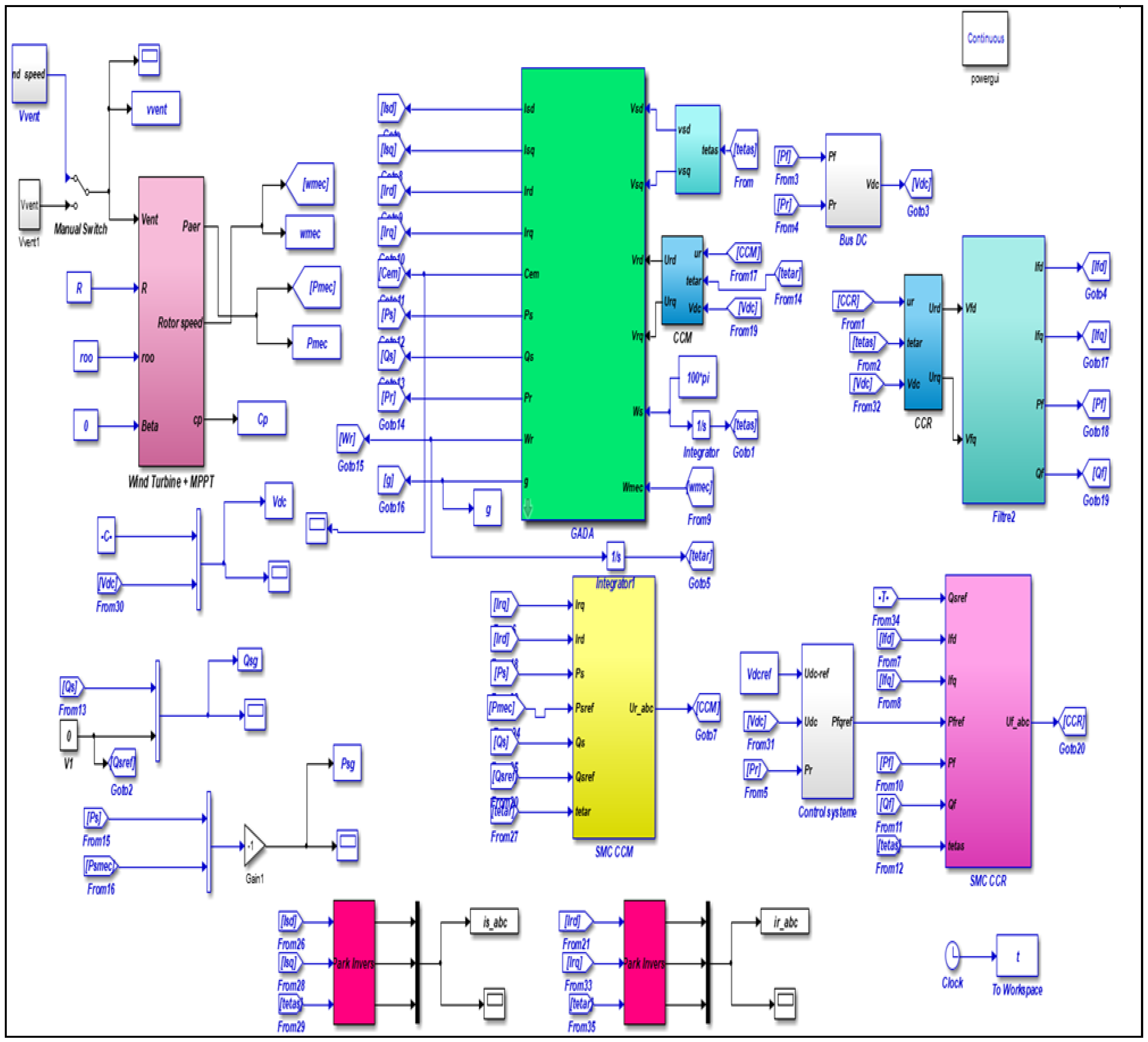
4. Results and Simulation

The tracking and robustness tests were carried out on Matlab and Simulink in order to validate the proposed model. To evaluate the performance of sliding mode control applied to a grid-connected wind power system, FPGA in the Loop was carried out.
In order to verify the results obtained by the simulations, FPGA in the Loop was proposed (Figure 2), which is realized with a co-simulation by the FPGA Nexys 4 DDR target. The machine’s model realized in Matlab/Simulink was converted into a digital model in order to facilitate the generation of the VHDL code using the “System Generator” tool. The sampling period used is of the order Ts = 5 μs, and the frequency linked to the FPGA is 50 MHz (Table A1).

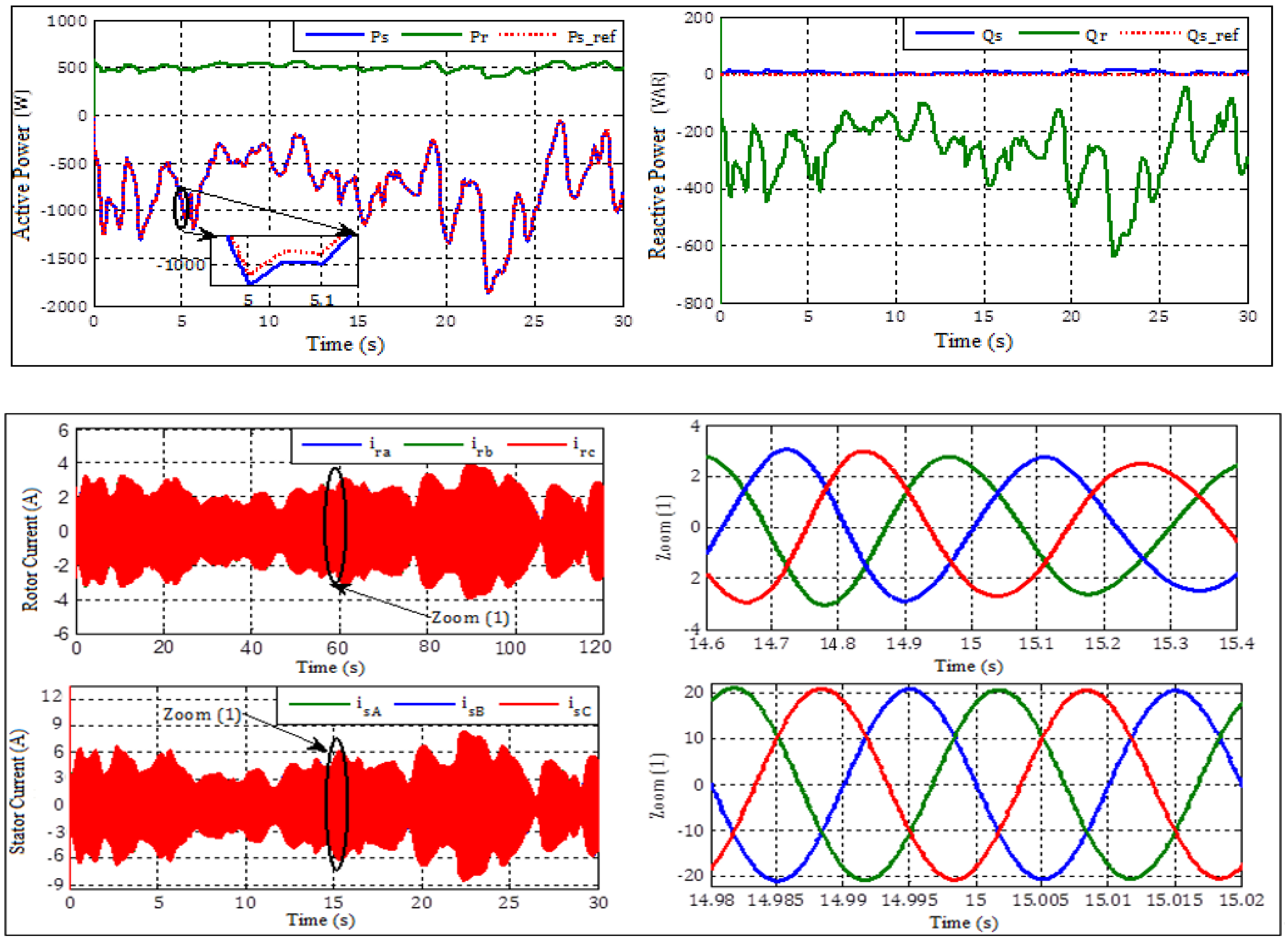
4.1. Real Wind Profile

The wind profile used for these tests is wind data from the Dakhla Morocco site (Figure 3).
We remark that the generator well follows the references of the powers without overshoot and with an almost null error.
Figure 4 present the THD for current and voltage.
The THD is clearly (6.29%) at the level of the rotor current, for only (0.16%) at the level of the stator current.

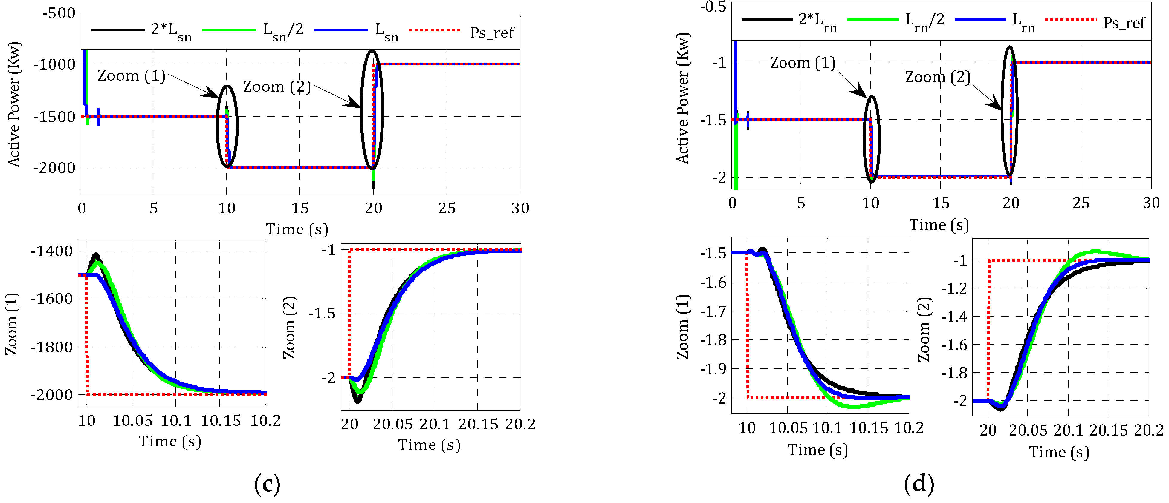
4.2. Step Wind Profile

Step references are applied to the active and reactive power of the system (Figure 5).
The results in Figure 6 show the following:
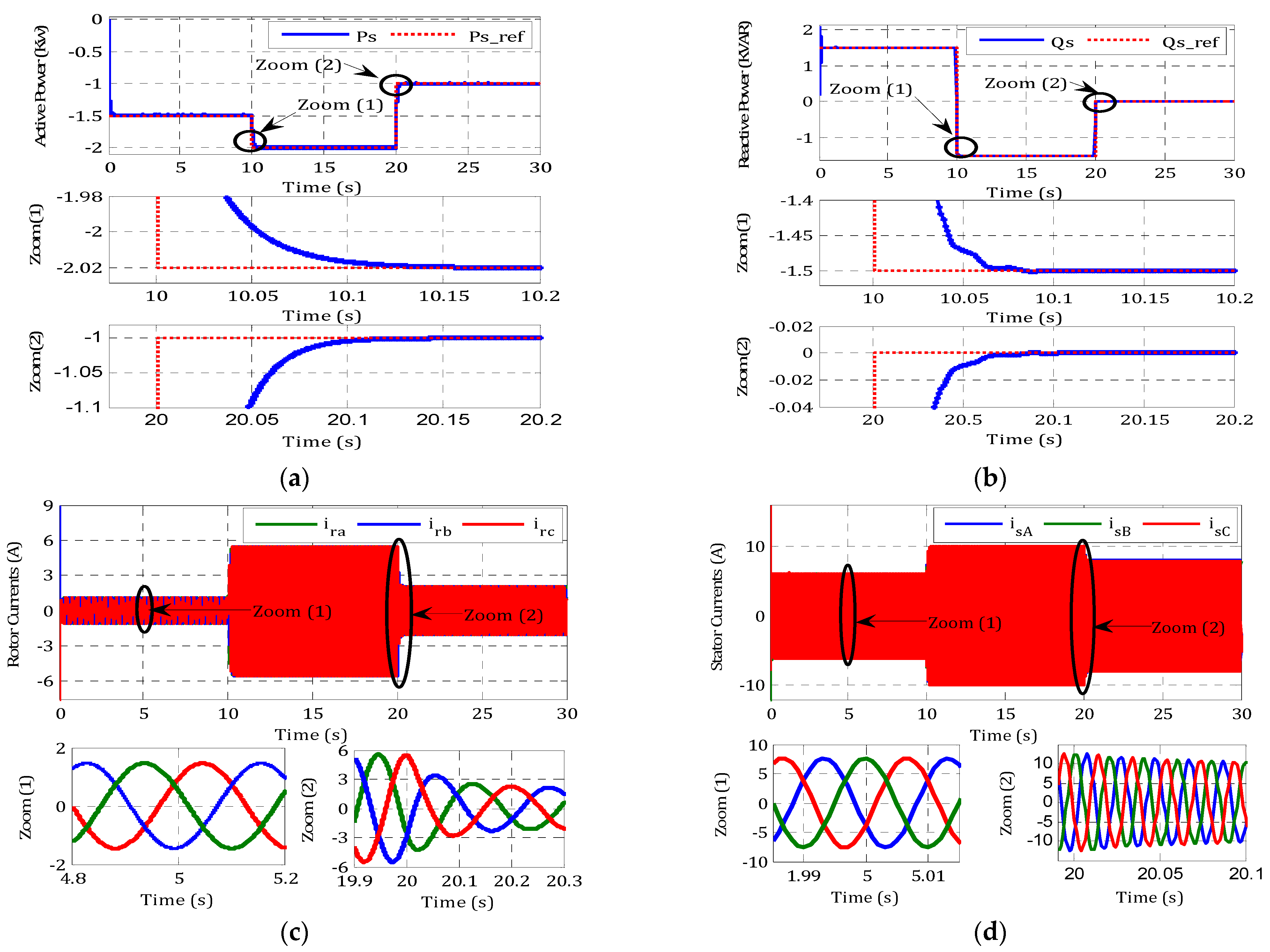
  • Better monitoring of active and reactive power.
  • Better power factor due to improved reactive power.
  • Very good performance monitoring with the references with an error of 0.067%.
  • Better responses of the currents Is and Ir despite the variation imposed by the torque.
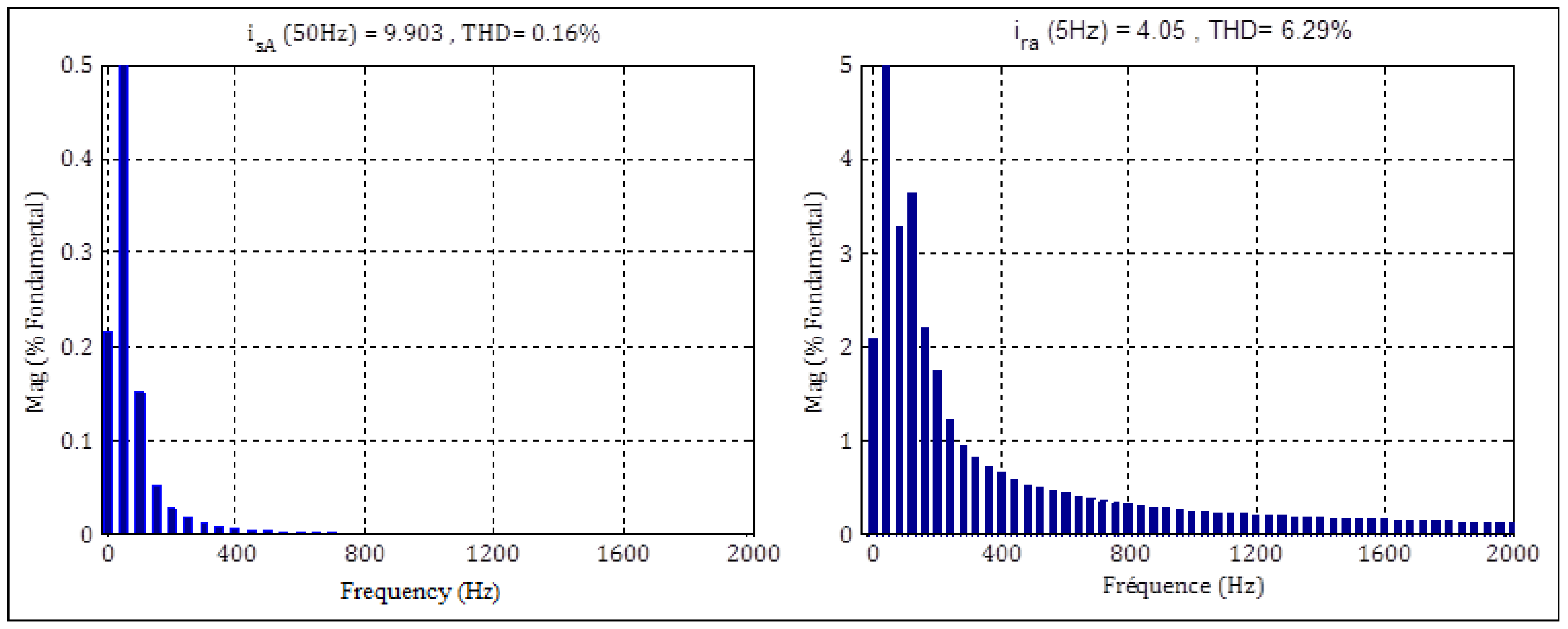
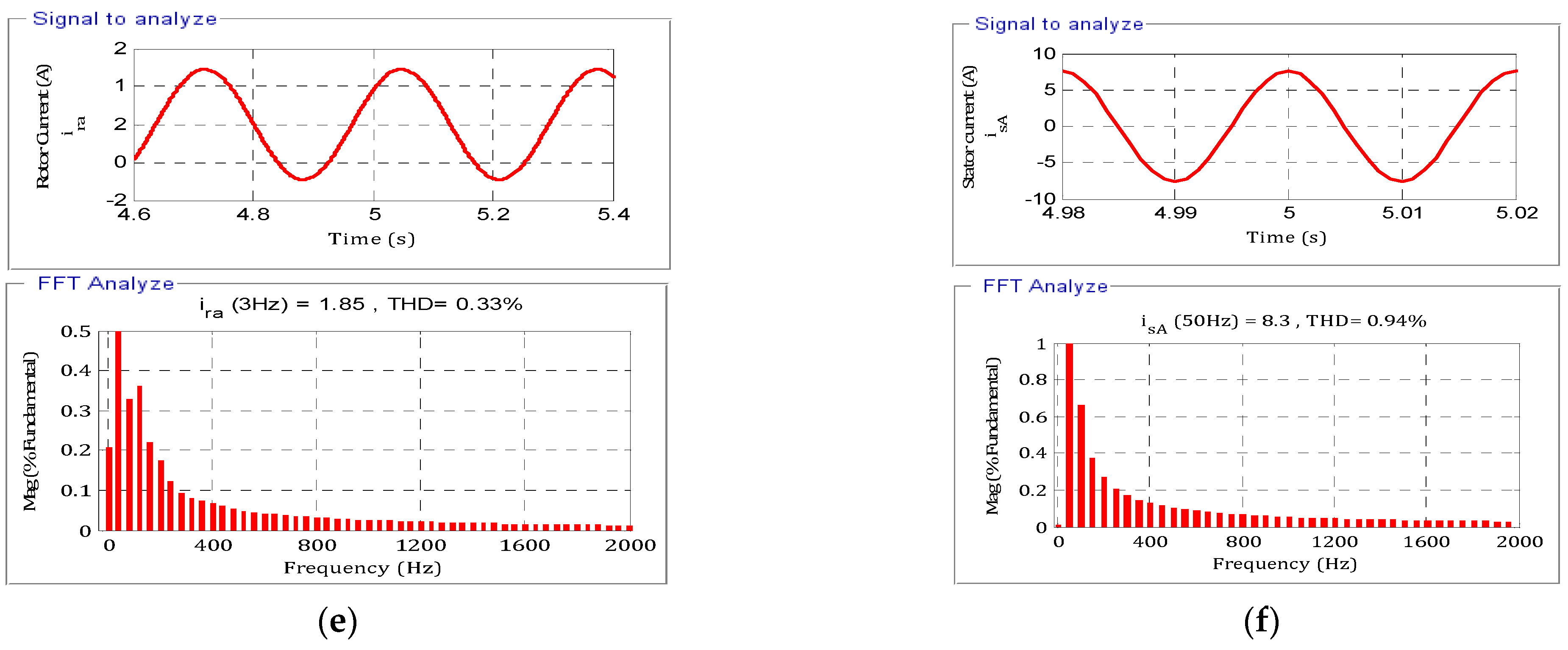
  • The form of the current is sinusoidal with a frequency of 50 Hz for the stator current and 3 Hz for the rotor current.
  • The THD is 0.33% for the current Ir and is 0.94% for the current Is.
To demonstrate the advantages and the superiority of the proposed control it is interesting to compare it with other techniques in the literature. It is noted here that these techniques were not performed under the same conditions because it is really rare to find many works done under similar conditions. From Table 1, it can be seen that the proposed control based offers a low total harmonic distortion (THD = 1.25%) compared with the other techniques. Additionally, it presents acceptable results in terms of rapidity and precision compared to other methods, which are characterized by Error = 0.15% and Tr = 0.015 s.

5. Conclusions

This work proposes an enhanced sliding mode control strategy to a variable wind speed-based DFIG-Generator. The performance of the control was verified through a co-simulation between the Matlab/Simulink environment and HIL-based FPGA. The simulation results and the comparative study confirmed that the proposed control is more suitable for a wind power conversion system based on the DFIG variable speed.

Author Contributions

Conceptualization, H.E.A.; methodology, M.K. and H.E.A.; software, S.M.; validation, H.E.A. and B.B; formal analysis, H.E.A., M.T., M.E.M. and M.L.; investigation, H.E.A.; resources, H.E.A.; data curation, H.E.A.; writing—original draft preparation, H.E.A.; writing—review and editing, M.B., E.H.A., S.M. and M.K.; visualization, M.K.; supervision, E.H.A., S.M., B.B., and M.M.; project administration, B.B.; funding acquisition, E.H.A. All authors have read and agreed to the published version of the manuscript.

Funding

This work is supported by Taif University Researchers Supporting Project number (TURSP-2020/292) Taif University, Taif, Saudi Arabia.

Acknowledgments

The authors would like to acknowledge Taif University Researchers Supporting Project number (TURSP-2020/292) Taif University, Taif, Saudi Arabia.

Conflicts of Interest

The authors declare no conflict of interest.

Nomenclature

Ωtturbine speed
Rs, Rrstator/rotor resistances
Rf, Lfresistances and inductance of filter
Lr, Lsstator/rotor inductances
Psactive power at stator
Qs, Qfreactive power to stator and filter
Paeroaerodynamic power
Cemelectromagnetic torque
Φ r, Φ srotor and stator flux
(vsd, vsq), (isd, isq)d/q stator voltages and currents
(vrd, vrq), (ird, irq)d/q rotor voltages and currents
(vgd, vgq), (igd, igq)grid voltages and currents
(vfd, vfq), (ifd, ifq)voltages and currents at the RL filter

Appendix A

Table A1. The DFIG and wind turbine parameters.
DFIG GeneratorWind Turbine
ParametersSymbolValuesParametersSymbolValues
Power GeneratorPs 1.5 KWRadius of the turbine bladeR20 m
Stator ResistanceRs4.85 ΩSpecific density of airρ1.22 kg/m3
Rotor ResistanceRr3.805 ΩTip-speed ratioλopt8
Stator InductanceLs274 mHOptimal power coefficientCp0.45
Rotor InductanceLr258 mH

References

  1. Rkik, I.; El, M.; Ed-dahhak, A.; Guerbaoui, M.; Lachhab, A. An enhanced control strategy based imaginary swapping instant for induction motor drives. Int. J. Electr. Comput. Engeuring 2022, 12, 1102–1112. [Google Scholar] [CrossRef]
  2. Alami, H.; Aroussi, E.M.; Ziani, M.; Bouderbala, B.B. Improvement of Direct Torque Control Applied To Doubly Fed Induction Motor Under Variable Speed. IJPEDS Int. J. Power Electron. Drive Syst. 2020, 11, 1511–1520. [Google Scholar]
  3. Taveiros, F.E.V.; Barros, L.S.; Costa, F.B. Back-to-back converter state-feedback control of DFIG (doubly-fed induction generator)-based wind turbines. Energy 2015, 89, 896–906. [Google Scholar] [CrossRef]
  4. Hammoumi, D.; El Bekkali, C.; Karim, M.; Taoussi, M.; El Ouanjli, M.; Bossoufi, B. Direct controls for wind turbine with PMSG used on the real wind profile of Essaouira-Morocco city. Indones. J. Electr. Eng. Comput. Sci. 2019, 16, 1229–1239. [Google Scholar] [CrossRef]
  5. Essallah, S.; Bouallegue, A.; Khedher, A. Integration of automatic voltage regulator and power system stabilizer: Small-signal stability in DFIG-based wind farms. J. Mod. Power Syst. Clean Energy 2019, 7, 1115–1128. [Google Scholar] [CrossRef] [Green Version]
  6. Bouderbala, M.; Bossoufi, B.; Aroussi, H.A.; Lagrioui, A.; Taoussi, M.; Ihedrane, Y.; El Ghamrasni, M. Modeling and power controls of wind energy conversion systems based on doubly fed induction generator. In Proceedings of the 2018 6th International Renewable and Sustainable Energy Conference (IRSEC), Rabat, Morocco, 5–8 December 2018; pp. 1–6. [Google Scholar] [CrossRef]
  7. Barkia, A.; Bouchiba, N.; Sallem, S.; Chrifi-Alaoui, L.; Drid, S.; Kammoun, M.B.A. A comparative study of PI and Sliding mode controllers for autonomous wind energy conversion system based on DFIG. In Proceedings of the 2016 17th International Conference on Sciences and Techniques of Automatic Control and Computer Engineering, STA 2016-Proceedings, Sousse, Tunisia, 9 December 2017; pp. 612–617. [Google Scholar] [CrossRef]
  8. Drhorhi, I.; El Fadili, A.; Berrahal, C.; Lajouad, R.; El Magri, A.; Giri, F.; Azar, A.T.; Vaidyanathan, S. Adaptive Backstepping Controller for DFIG-Based Wind Energy Conversion System; Elsevier Inc.: Amsterdam, The Netherlands, 2021; ISBN 9780128175828. [Google Scholar]
  9. Bossoufi, B.; Karim, M.; Taoussi, M.; Aroussi, H.A.; Bouderbala, M.; Motahhir, S.; Camara, M.B. DSPACE-based implementation for observer backstepping power control of DFIG wind turbine. IET Electr. Power Appl. 2020, 14, 2395–2403. [Google Scholar] [CrossRef]
  10. Giannakis, A.; Karlis, A.; Karnavas, Y.L. A combined control strategy of a DFIG based on a sensorless power control through modified phase-locked loop and fuzzy logic controllers. Renew. Energy 2018, 121, 489–501. [Google Scholar] [CrossRef]
  11. Ali, M.M.; Youssef, A.R.; Ali, A.S.; Abdel-Jaber, G.T. Comparative study of different pitch angle control strategies for DFIG based on wind energy conversion system. Int. J. Renew. Energy Res. 2019, 9, 157–163. [Google Scholar]
  12. Yang, X.; Liu, G.; Li, A.; Le, V.D. A predictive power control strategy for DFIGs based on a wind energy converter system. Energies 2017, 10, 1098. [Google Scholar] [CrossRef]
  13. Yang, X.; Liu, G.; Le, V.D.; Le, C.Q. A novel model-predictive direct control for induction motor drives. IEEJ Trans. Electr. Electron. Eng. 2019, 14, 1691–1702. [Google Scholar] [CrossRef]
  14. Ayyarao, T.S.L.V. Modified vector controlled DFIG wind energy system based on barrier function adaptive sliding mode control. Prot. Control Mod. Power Syst. 2019, 4, 1193. [Google Scholar] [CrossRef] [Green Version]
  15. Aounallah, T.; Essounbouli, N.; Hamzaoui, A.; Bouchafaa, F. Algorithm on fuzzy adaptive backstepping control of fractional order for doubly-fed induction generators. IET Renew. Power Gener. 2018, 12, 962–967. [Google Scholar] [CrossRef]
  16. Kelkoul, B.; Boumediene, A. Stability analysis and study between classical sliding mode control (SMC) and super twisting algorithm (STA) for doubly fed induction generator (DFIG) under wind turbine. Energy 2021, 214, 118871. [Google Scholar] [CrossRef]
  17. Soomro, M.A.; Memon, Z.A.; Kumar, M.; Baloch, M.H. Wind energy integration: Dynamic modeling and control of DFIG based on super twisting fractional order terminal sliding mode controller. Energy Rep. 2021, 7, 6031–6043. [Google Scholar] [CrossRef]
  18. Chojaa, H. Maximum Power Extraction of Five-Phase Pmsg Based Wecs by Adopting an Improved Fractional Order Sliding Mode Strategy. Energy Rep. 2021, 11, 55–74. [Google Scholar] [CrossRef]
  19. Le, V.; Li, X.; Li, Y.; Dong, T.L.T.; Le, C. An innovative control strategy to improve the fault ride-through capability of DFIGs based on wind energy conversion systems. Energies 2016, 9, 69. [Google Scholar] [CrossRef]
  20. Bossoufi, B.; Karim, M.; Taoussi, M.; Aroussi, H.A.; Bouderbala, M.; Deblecker, O.; Motahhir, S.; Nayyar, A.; Alzain, M.A. Rooted tree optimization for the backstepping power control of a doubly fed induction generator wind turbine: Dspace implementation. IEEE Access 2021, 9, 26512–26522. [Google Scholar] [CrossRef]
  21. Apata, O.; Oyedokun, D.T.O. An overview of control techniques for wind turbine systems. Sci. Afr. 2020, 10, e00566. [Google Scholar] [CrossRef]
  22. Bouderbala, M.; Bossoufi, B.; Deblecker, O.; Alami Aroussi, H.; Taoussi, M.; Lagrioui, A.; Motahhir, S.; Masud, M.; Alraddady, F.A. Experimental Validation of Predictive Current Control for DFIG: FPGA Implementation. Electronics 2021, 10, 2670. [Google Scholar] [CrossRef]
  23. Djoudi, A.; Bacha, S.; Iman-Eini, H.; Rekioua, T. Sliding mode control of DFIG powers in the case of unknown flux and rotor currents with reduced switching frequency. Int. J. Electr. Power Energy Syst. 2018, 96, 347–356. [Google Scholar] [CrossRef]
  24. Liao, K.; He, Z.; Xu, Y.; Chen, G.; Dong, Z.Y.; Wong, K.P. A Sliding Mode Based Damping Control of DFIG for Interarea Power Oscillations. IEEE Trans. Sustain. Energy 2017, 8, 258–267. [Google Scholar] [CrossRef]
  25. Lhachimi, H.; Sayouti, Y.; El Kouari, Y. Optimal improvement of direct power control strategy based on sliding mode controllers. Comput. Electr. Eng. 2018, 71, 637–656. [Google Scholar] [CrossRef]
  26. Chakib, M.; Essadki, A.; Nasser, T. A comparative study of PI, RST and ADRC control strategies of a doubly fed induction generator based wind energy conversion system. Int. J. Renew. Energy Res. 2018, 8, 964–973. [Google Scholar]
  27. Bossoufi, B.; Karim, M.; Lagrioui, A.; Taoussi, M. FPGA-Based Implementation nonlinear backstepping control of a PMSM Drive. IJPEDS Int. J. Power Electron. Drive Syst. 2014, 4, 12–23. [Google Scholar] [CrossRef]
  28. Bossoufi, B.; Karim, M.; Lagrioui, A.; Taoussi, M. FPGA-Based Implementation Sliding Mode Control and nonlinear Adaptive Backstepping control of a Permanent Magnet Synchronous Machine Drive. Wseas Trans. Syst. Control 2014, 9, 86–100. [Google Scholar]
  29. Sghaier, N.; Ramzi, T.; Gdaim, S.; Bossoufi, B.; Mimouni, M.F. Backstepping control of induction motor using Xilinx System Generator: FPGA-based implementation. Int. J. Emerg. Sci. 2013, 3, 289–302. [Google Scholar]
  30. Bossoufi, B.; Karim, M.; Ionita, S.; Lagrioui, A. Nonlinear non Adaptive Backstepping with Sliding-Mode Torque Control Approach for PMSM Motor. J. Electr. Syst. JES 2012, 8, 236–248. [Google Scholar]
  31. Bossoufi, B.; Karim, M.; Ionita, S.; Lagrioui, A. The Optimal Direct Torque Control of a PMSM drive: FPGA-Based Implementation with Matlab & Simulink Simulation. J. Theor. Appl. Inf. Technol. JATIT 2011, 28, 63–72. [Google Scholar]
  32. Bossoufi, B.; Karim, M.; Ionita, S.; Lagrioui, A.; Iana, G. Matlab & Simulink Simulation with FPGA-Based Implementation Sliding Mode Control of a Permanent Magnet Synchronous Machine Drive. Wseas Trans. Syst. Control 2011, 6, 92–103. [Google Scholar]
  33. Bossoufi, B.; Karim, M.; Ionita, S.; Lagrioui, A. Indirect Sliding Mode Control of a Permanent Magnet Synchronous Machine: FPGA-Based Implementation with Matlab & Simulink Simulation. J. Theor. Appl. Inf. Technol. JATIT 2011, 29, 32–42. [Google Scholar]
  34. El Ouanjli, N.; Derouich, A.; El Ghzizal, A. Direct torque control of doubly fed induction motor using three-level NPC inverter. Prot Control Mod Power Syst 2019, 4, 17. [Google Scholar] [CrossRef] [Green Version]
  35. Saady, I.; Karim, M.; Bossoufi, B.; Motahhir, S.; Adouairi, M.S.; Majout, B.; Lamnadi, M.; Masud, M.; Al-Amri, J.F. Optimisation for a Photovoltaic Pumping System using Indirect Field Oriented Control of Induction Motor. Electronics 2021, 10, 3076. [Google Scholar] [CrossRef]
  36. Taoussi, M.; Bossoufi, B.; Bouderbala, M.; Motahhir, S.; Alkhammash, E.H.; Masud, M.; ZineLabidine, N.; Karim, M. Implementation and Validation of Hybrid Control for DFIG Wind Turbine Using FPGA Controller Board. Electronics 2021, 10, 3154. [Google Scholar] [CrossRef]
Figure 1. Wind system structure [20].
Electronics 11 00116 g001
Figure 2. SMC control for wind turbine.
Electronics 11 00116 g002
Figure 3. Real variable wind speed system response.
Electronics 11 00116 g003
Figure 4. Analyzed THD (%).
Electronics 11 00116 g004
Figure 5. Co-simulation experimental results with step references: (a) active power, (b) reactive power, (c) rotor current, (d) stator current, (e) THD rotor current, and (f) THD stator current.
Electronics 11 00116 g005aElectronics 11 00116 g005b
Figure 6. Co-simulation experimental results robustness, (a) Active Power with 2*Rn, (b) Active Power with Rn/2, (c) Active Power with Lsn/2. (d) Active Power with Lrn/2.
Electronics 11 00116 g006aElectronics 11 00116 g006b
Table 1. Comparison with technical control.
Publication PaperTechnical MethodsResponse Time(s)Error (%)THD (%)
[27]Fuzzy SMC0.32--
[28]PI0.0301.25-
RST0.0280.06-
[26]SMC based backstepping0.05-2.98
[13]DTC0.12-18.8
FSC0.16-8.26
MPDC0.15-8.17
Proposed techniqueProposed sliding mode control 0.0150.151.25
Publisher’s Note: MDPI stays neutral with regard to jurisdictional claims in published maps and institutional affiliations.

