Article

Validation of a Platform for the Electrostatic Characterization of Textile

Centre for Textile Science and Engineering, Department of Materials, Textiles and Chemical Engineering, Ghent University, Zwijnaarde, 9052 Ghent, Belgium
*
Author to whom correspondence should be addressed.
Electronics 2022, 11(1), 115; https://doi.org/10.3390/electronics11010115
Submission received: 8 December 2021 / Revised: 24 December 2021 / Accepted: 27 December 2021 / Published: 30 December 2021
(This article belongs to the Special Issue Advanced Soft Materials in Electronic Sensor and Actuators)

Abstract

:
Floor covering samples of different thickness, pile height, pile design, materials, construction methods, and applied finishes were selected for electrostatic characterization with a standard plotter platform and a newly designed digital platform. There is an existing standard ISO 6356 in which the voltage generated by a human walking on the carpet is measured with human involvement under controlled conditions. A walking person performs the original test procedure to generate the electrostatic charge and manually calculates results. In contrast, the newly designed system does not require a person to calculate peaks and valleys for the generated electrostatic charges, which offers advantages in terms of accuracy, consistency, and reproducibility, and eliminates human error. The electronic platform is extended with an automated foot for a fully automated test, called “automatic mode”, that has a fixed capacitive and resistive circuit, in replace of human body resistance, and capacitance that varies from person to person and over time. The procedure includes both the old and new platforms, where the new platform is placed in a “human walking” mode to compare the two and validate the new device. Next, all the floor coverings are tested in automatic mode with the automated foot to compare and validate results. We conclude that the new testing device can fully characterize the electrostatic behavior of textile without the involvement of a human, which offers advantages in terms of accuracy, consistency, and reproducibility.

1. Introduction

Static electricity may cause an unpleasant, but otherwise harmless, shock when a person touches a door handle after walking just a few steps on a dry, insulated carpet. Static electricity was the first type of electric process known to man [1,2,3]. This has resulted in the appearance of several excellent, but specialized, treatises on the topic. Nevertheless, there still seem to be numerous misconceptions and misunderstandings about static electricity in textile products [3,4].
Textiles and other materials can be charged with static energy induced by friction. This can be quite a problem, especially with floor coverings, as people walking on them can accumulate high-voltage electrical charge. The discharge of built-up static charge can lead to discomfort for people, influence or damage electronic equipment, or be a fire hazard, for example, at a gasoline station [5]. One of the tests to determine the electrostatic characteristics is the walking test, defined in the ISO 6356 standard [6]. In this test the voltage generated by a person walking on carpet is measured.
Electrostatic charges are produced when two surfaces come in contact with each other and are then separated. When there is contact between the two surfaces, there is a superposition of the atomic fields in the contact area where charges can exchange. If one of the bodies is an insulator, the transferred charges cannot move around, resulting in charge build-up. One of the two bodies will show positive excess of charges while the other will show a negative excess. Many theories assume that when the material is in contact, charge transfer is only concerned with electrons. Some modern theories also consider two charge exchange mechanisms: electron and positive ion transfer [7]. It is the chemical and physical composition of the materials that mainly determine the polarity and the amount of charge transfer and built-up. Further factors that are important for the charge build-up and transfer of charges between the surfaces are electrical surface resistance and volumetric resistance of the materials. The surface texture, the pressure of contact, the distance of separation, and speed of friction or separation are the main parameters that determine the generation of electrostatic charges. External factors that can affect the generation of electrostatic charges on the surface include the temperature, relative humidity, and the quality and quantity of air around the surfaces. Apart from these main factors, other factors play a role in determining the level of built-up charge on the body. These include footwear, floorcovering, surface coating, walking speed, step height, and step pressure [8,9,10].
From a body voltage of 6 kV, most people will observe a painful shock. The threshold under which discharge occurs while touching an object is 2kv, while from 4kv in conditions of low relative humidity, while walking on synthetic carpets with an electrically insulated coating, a person may experience a build-up of body voltage up to 25 kV. For laminated floorcoverings, the highest body voltage recorded is 12 kV, equivalent to a discharge energy of 10 mJ [11]. A discharge above 10 mJ can be dangerous for humans. Despite the fact that proof for immediate and adverse effects from a weak electrical field is weak and controversial, it is accepted that having a charged body has an impact on human health [4,10]. In addition to having a painful sensation, spark discharge could lead to dangerous situations such as dropping a heavy or hot flammable liquid, causing injury. This electrical spark can cause ignition of highly flammable materials.
Sensitive electronic circuits could also be at risk of damage from spark discharge. In addition, damage to the computing network in offices or research facilities could cause considerable damage for which a floorcovering manufacturer could be held liable based on the product liability act. A further disadvantage of the build-up of static charge is the attraction of dust, dirt, and smoke particles, resulting in dirty surfaces [2,4,12,13].
Some of the standard test method to evaluate the electrostatic behavior of floorcoverings and laminate are EN 14041, valid since 2004 and amended in 2005 and 2006. It sets the acceptable limits for the categorization of all floor coverings, excluding in flare-up risk regions. The provisions of testing methods talk about EN 1081 for ohm resistance measurement and about EN 1815 and ISO 6356 for measurement of body voltage in a walking test under the controlled condition of 23 °C ± 2 °C and 25% ± 2% relative humidity (RH). The purpose of development of EN 1081 was for resilient floor coverings and the EN 1815 standard for resilient and laminate floor coverings [4,10,14].
Electrostatic charges are produced on a surface by friction or tapping against another surface. There are different modes of electrostatic generation and collection of charges from the tapping and frictional surfaces. If we consider the geometry of electrostatic devices [15], there are four different modes (Figure 1): the vertical contact separation mode [16], the lateral sliding mode [17], the single electrode mode [18], and the free standing sliding mode [19].
Although each geometry of devices based on the two principles, contact electrification and electrostatic induction, there are different parameters like speed of contact, pressure, time of contact, frequency that might have effect on the generation of electrostatic charges [20,21,22].

2. Materials and Methods

A total of 10 different floor coverings of different thickness, pile height, pile design, material, construction, and applied finish were selected to compare the new testing device with the standard testing device. The thickness of the floor covering was measured according to the ISO 1765; Machine made textile floorcoverings—Determination of thickness. Basic information about the samples is given in Table 1.
A new system was designed to measure electrostatic charging. The system is automated in such a way that there was no longer a need for a person to perform the test. The purpose was to provide an accurate, consistent, and reproducible measurement. The steps were performed in a homogeneous pattern across the carpet, resulting in a reliable measurement. The walking commands were based on the protocol for CNC machines, offering the possibility to control the system through a USB connection from a PC. The set-up is shown in Figure 2.
The design provides many parameters that could be varied. The step height could be set to a fixed height, to deliver the same step movement during the entire test. By changing the step height, the influence of this parameter were measured. The regulated pressure for the pneumatic cylinder defined the force applied by the foot on the carpet. Together with the surface area of the sole, it determined the equivalent mass of a person. The stepping frequency was fixed to provide a stable build-up of static charges. The device has an extra testing mode that does not use the automated foot but requires a human to hold the probe and walk on the carpet: this mode is called the human walking mode (HWM). As the first test, the human walking mode was used for the comparison of its results to the already existing standard plotter results (METRAWATT SE 120) making use of a KEITHLY’S Electrometer 610 C, as shown in Figure 3.
Figure 4 shows the schematic diagram of the new electrostatic characterization set up. The Human Body Model (HBM) was used to provide an electric equivalent for the test person. This consists of a capacitor of 100 pF and a resistor of 1.5 kΩ. The circuit replaces the test person in the charging cycle. The generated charge can measure up to 15 kV, which is scaled down by a capacitive voltage divider. The division by 100,000 gives an output of 100 mV when the generated charge is 10 kV, which is an easy to process signal. To avoid problems with the high voltages, all the high voltage components are placed on a separate board made of Perspex. The signal conditioning on the scaled down voltage was done on a normal circuit board. In order not to influence the charge, the input of the circuit was a high impedance buffer. The low bias current high impedance operational amplifier had a neglectable influence on the charge. The input signal was then conditioned further. It was filtered to remove noise at higher frequencies. Two Sallen-Key low pass filters in cascade provided a fourth-order filter with a sharp cut-off at 20 Hz. An extra notch filter at 50 Hz was added in order to reduce the influence of the AC power net as much as possible. The filtered signal was then amplified in order to use the whole range of the ADC. The ADC read the signal at a sampling rate of 100 Hz.
The data read by the ADC were transmitted to a graphical user interface (GUI) on the PC and displayed on a real time chart. It offered direct feedback to the user for optimized control. The user interface also controlled all parts of the mechanical system offering a fully automated test procedure. The GUI thus provided central control over the system, including set-up and calibration of the system. An extra screen was added to provide easy reviewing of the previously recorded data. The goal of the walking test was to determine the maximum accumulated charge over the person or its equivalent. This was done by averaging both the five highest valleys and the five highest peaks of the measured voltage. Once all the data was acquired, an algorithm automatically detected these valleys and peaks. The output was projected on the chart to provide immediate feedback for the user. All results were also saved in a folder of preference, making fast data collection possible.
For the new device, the data was read by a National Instrument DAQ and recorded through a graphical user interface (GUI) on the PC, and displayed on a real-time chart. It offered direct feedback to the user for optimized control. The user interface also controlled all parts of the mechanical system offering a fully automated test procedure. The GUI thus provided central control over the system, including the set-up and calibration of the system. An extra screen was added to provide easy reviewing of the previously recorded data.
The goal of the walking test is to determine the maximum accumulated charge over the person or its equivalent. This is done by averaging both the five highest valleys and the five highest peaks of the measured voltage over a 60 s test interval. Once all the data were acquired, an algorithm automatically detected these valleys and peaks. The output was projected on the chart to provide immediate feedback for the user. All results were also saved in a folder of preference, making fast data collection possible. The Standard plotter (METRAWATT SE 120) with KEITHLY’S Electrometer 610 C and the probe was used to test the electrostatic charged developed on different floorcoverings according to ISO 6356 as shown in Figure 3 Other necessary tools and auxiliaries are given below
  • Test Sandals BAM
  • Ethanol (95% conc.) to clean the soles
  • Humidity and Temperature sensor to record the environment
  • Sample cutting scissor
  • Scoured cotton (free of finish or detergent) for cleaning of sole
  • Sandpaper (P280 to P360) to clean sandal
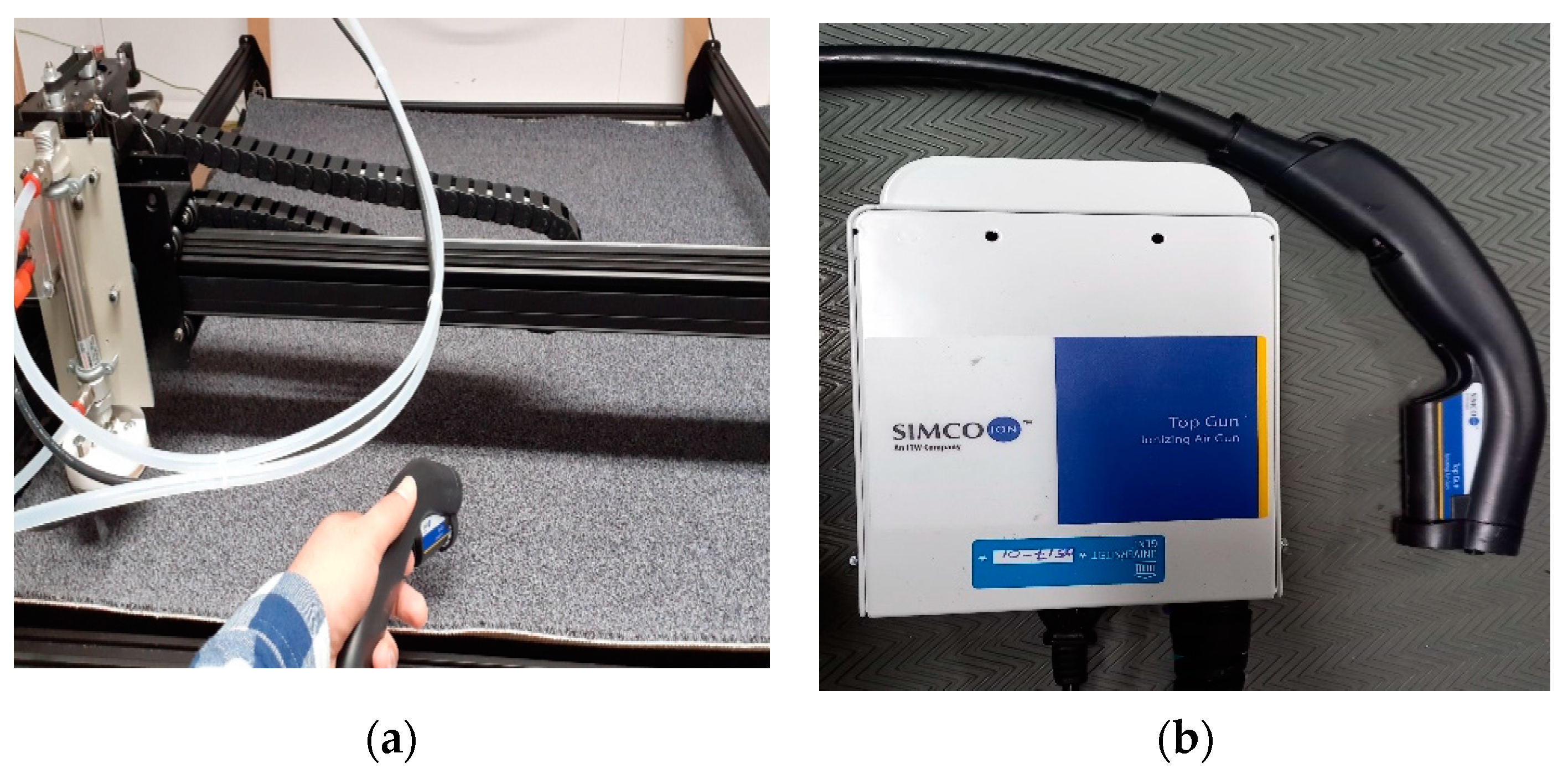
  • Ionizing Gun to discharge the floorcoverings
The new electronic data acquisition device plotter (DAQ) was custom created at our research group. This device has two modes: human walking mode (HWM), and automated foot mode (AFM). In this paper, the human walking mode is discussed in order to determine if the old plotter, which is the standard testing device, can be replaced by the new automated plotter HWM mode.

2.1. Method

Before doing the testing of floorcoverings, conditioning of test samples was performed for 7 days at a temperature of (23 ± 2) °C and relative humidity of (25 ± 2)% and all tests occurred at these values from standard ISO 6356. Each floor covering sample was evaluated five times on the old plotter and five times with the new DAQ electrostatic evaluating platform in HWM mode. Only one test person was used, and this person was trained to walk according to standard ISO 6356.
The value of generated electrostatic charge for all samples was checked with the standard plotter. The five lowest valleys and five highest peaks in the 60-s testing interval were manually determined according to the set values of different scales. There were three different scales of 10, 30, and 100 on the electrometer that were used for lower, medium, and higher electrostatic value floorcoverings.
The value of the generated electric charge for all samples were next checked with the HWM, where the five lowest valleys and five highest peaks were automatically determined. For the grounding of the floorcoverings an air gun was used. There were five repeats per floorcovering at different positions has been done on each plotter. Then results were compared to check the validity of this test procedure and the new setup. All the floorcoverings were also tested by automated foot of the new device. Figure 5a,b show the air gun set up to remove the residual charges on the floorcoverings. The residual charge was removed before starting each test. Figure 6 shows the graphical user interface for the automated tester with human walking and automatic foot test options. With this GUI (graphical user interface), it is straightforward to change the different testing settings and quickly review the previous testing data.

2.2. Statitical Analysis

The response values for highest peaks and valleys for the standard and new plotter were collected and data was analyzed using Statistical Package for the Social Sciences statistics software (SPSS V.26, IBM Corporation, New York, NY, USA). The responses generated by the 10 floorcoverings on standard and new devices were statistically analyzed including descriptive method and univariate analysis. The level of statistical significance for the analysis was set at α = 0.05, and as variables the floorcoverings (sample no given in Table 1) and the platform (old or new), were chosen. To deduce whether the highest peaks and valleys indicate a relationship between the variables (Quality, Platform), the p-values were examined. If the p-value of HP (Highest Peaks) and HV (Highest Valleys) was greater than 0.05 (p > 0.05), then there was not a statistically significant difference for the variables, and vice versa.

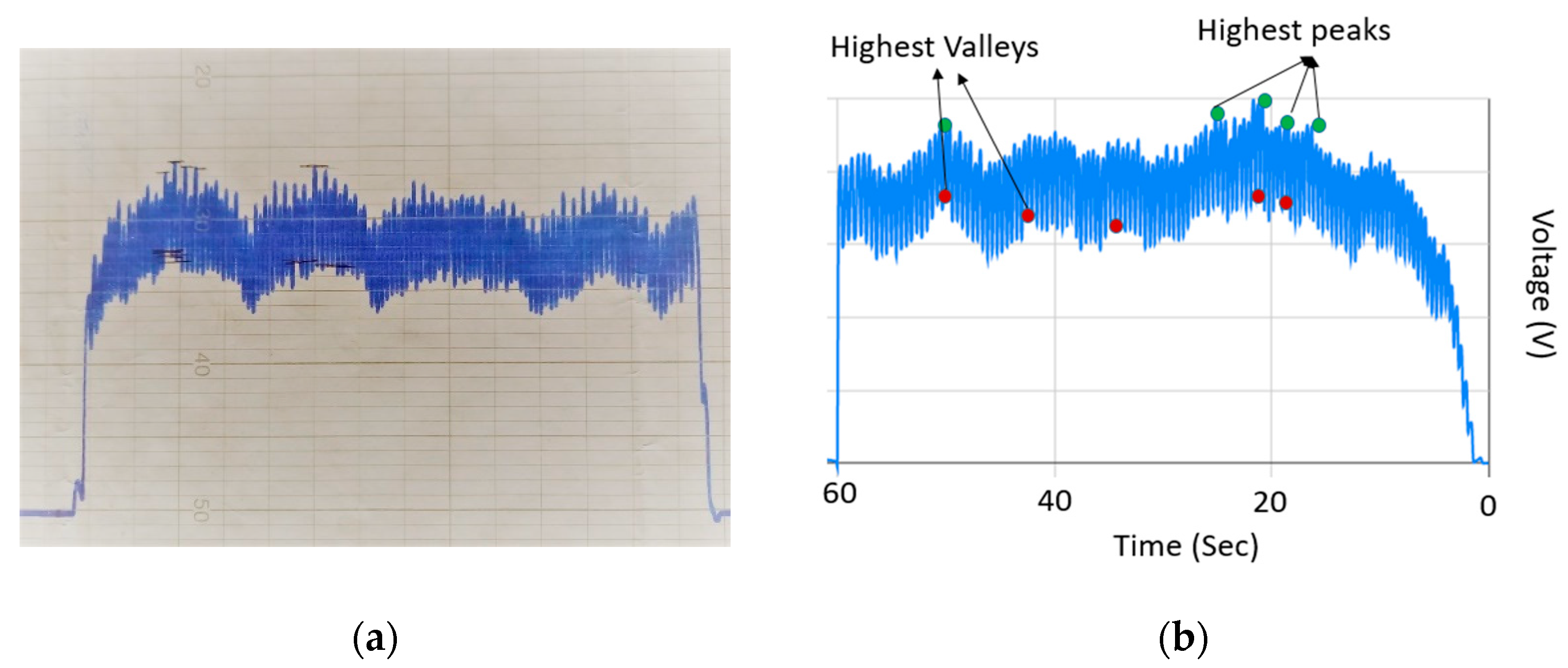
2.3. Effective Graphical Display of Data

We present bar charts that show the difference of means of HP (Highest Peaks) and HV (Highest Valleys) with standard deviation interval with quality and platform as fixed or X variables.

3. Results and Discussion

The electrostatic characterization graph plotted with the standard plotter with the new plotter is shown in Figure 7.

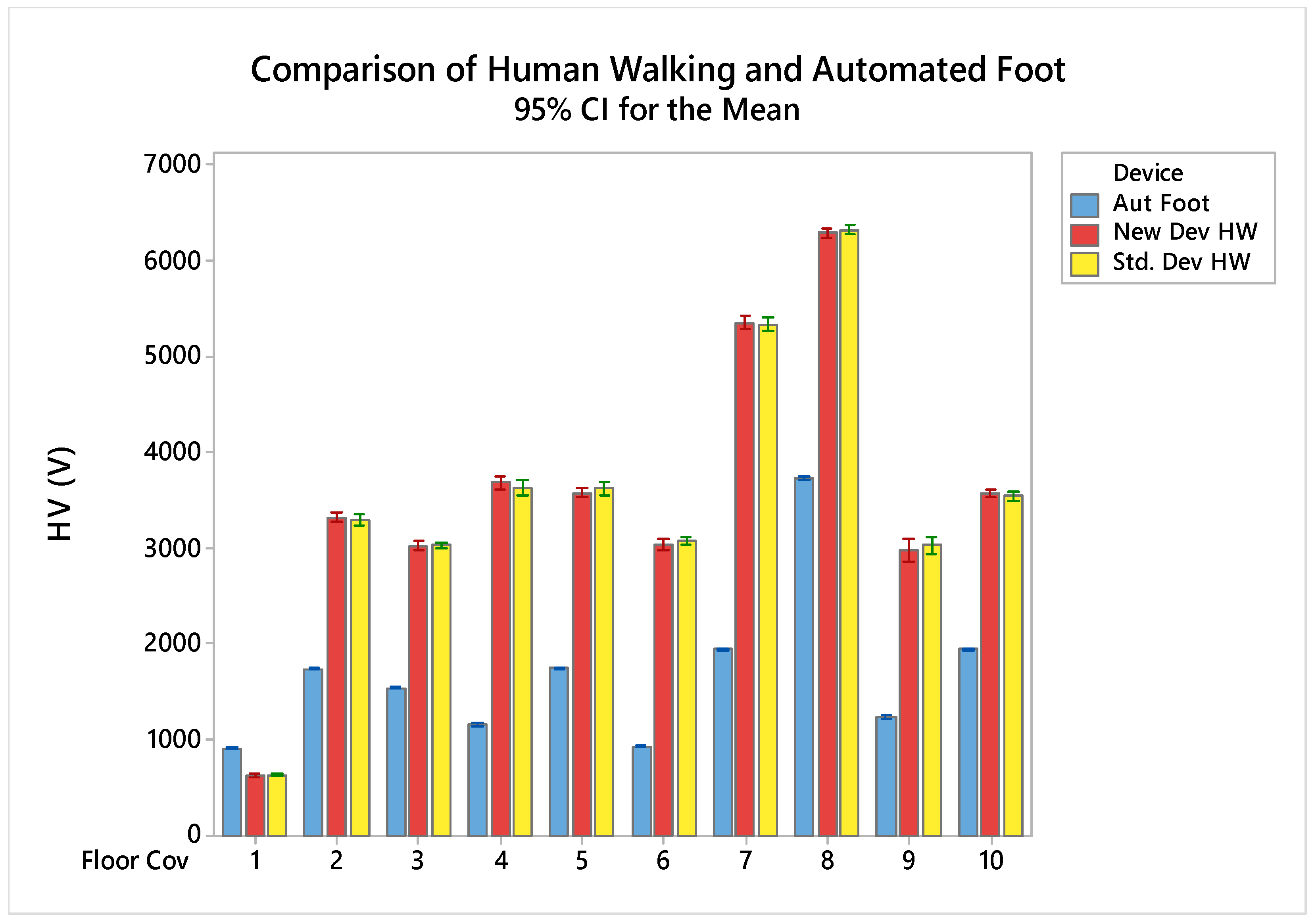
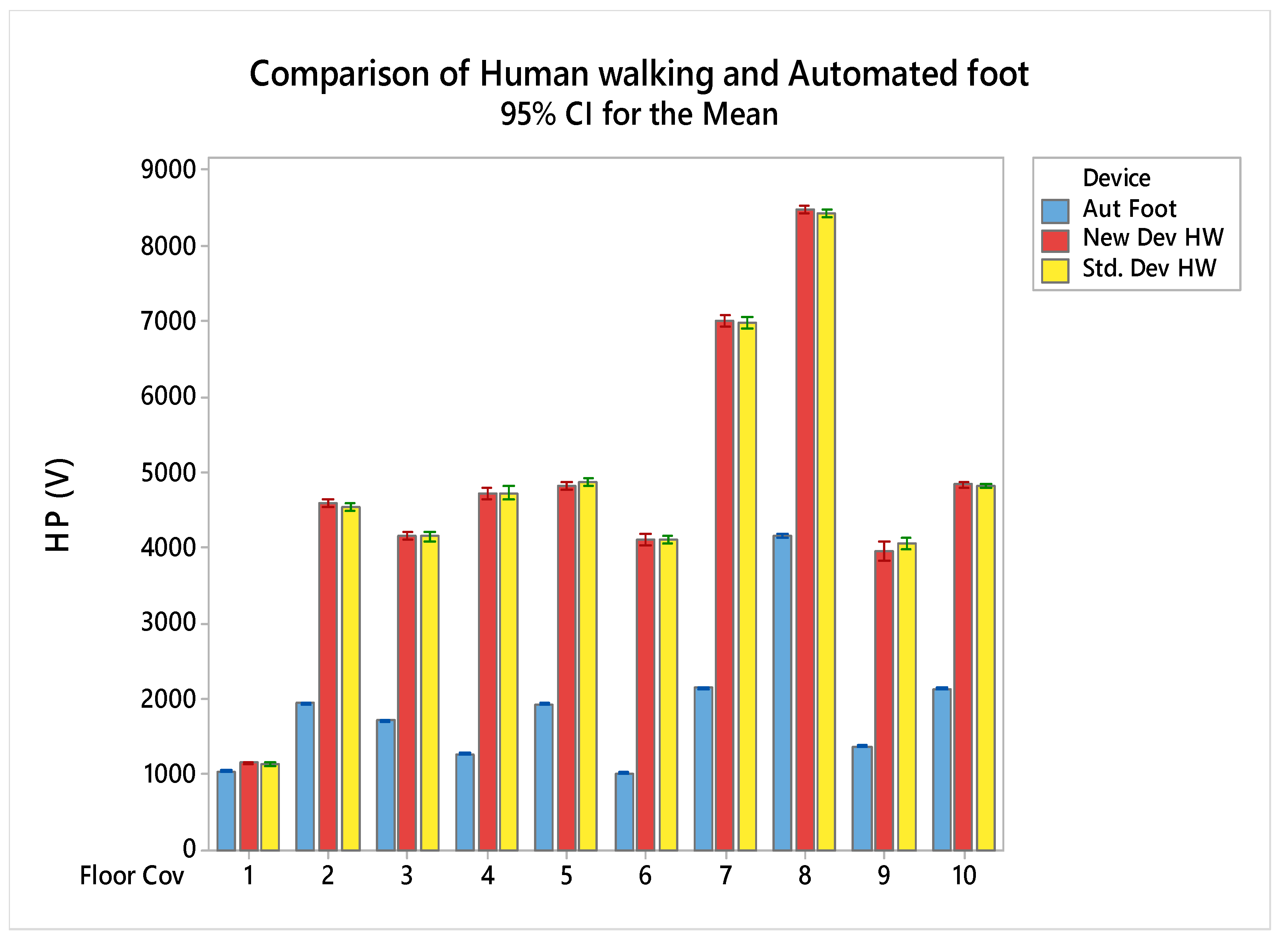
3.1. Validation of Human Walking Mode of New Device

To validate the human walking mode of the new device, univariate analysis was performed and results are summarized in Table 2, for the highest peaks and highest valleys respectively.
From the univariate analysis as given in Table 2 and Table 3, it was found that the highest peaks and highest valleys as determined by the new plotter were not statistically significantly different from the peaks and valleys of the standard device, only the sample type was significant. The graphical representation of the results of all floorcoverings for the highest peaks and valleys are given in Figure 8 and Figure 9 that show the highest peaks (Volt) and highest valleys as dependent variable and with floorcoverings samples and platform (New Device, Std. Device with KEITHLY’S Electrometer 610 C) as variable to show the difference of means and standard deviation as interval. We can conclude that the new plotter can be used as a recording tool for the human walking mode, replacing the old plotter.

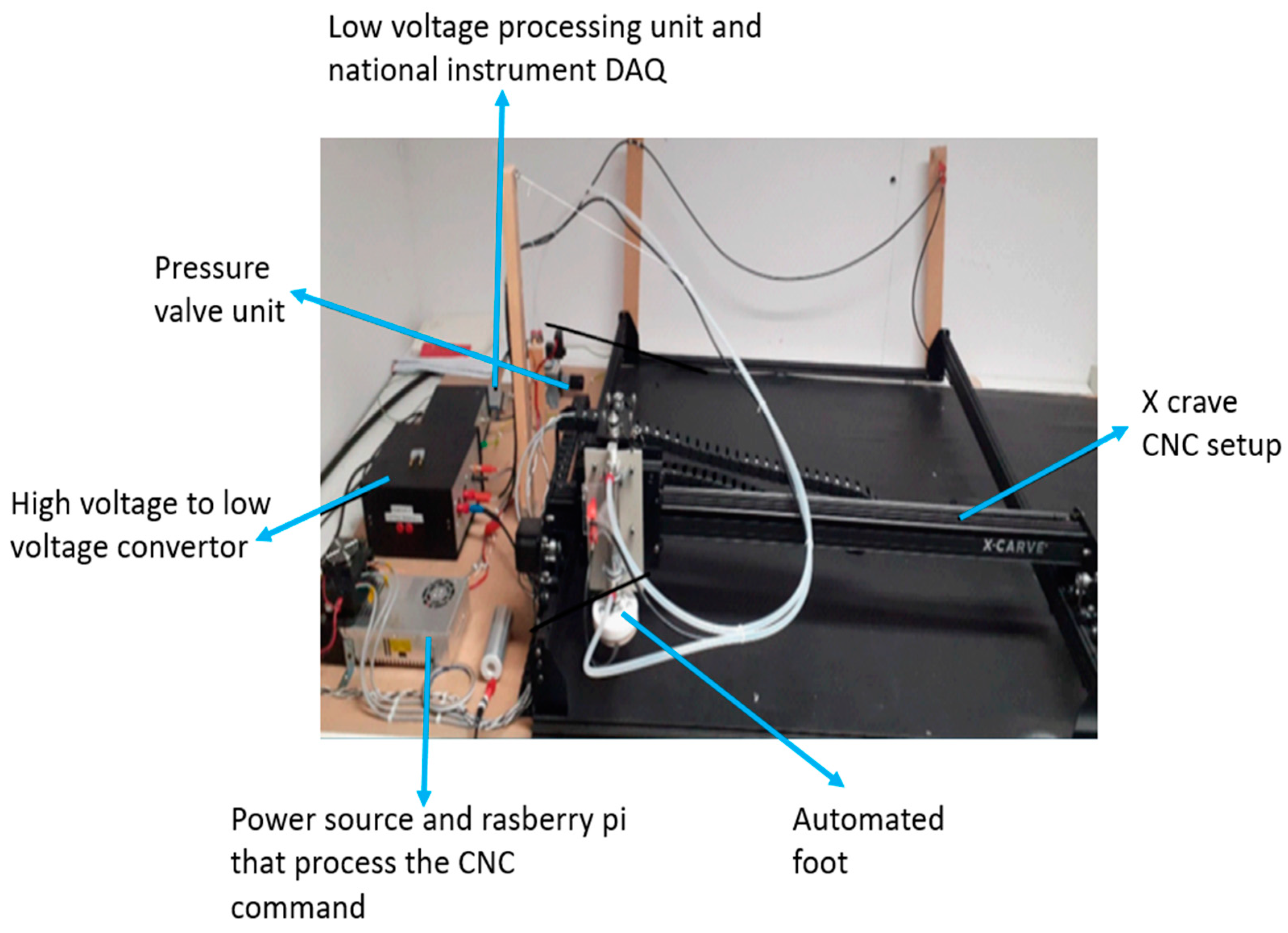
3.2. Automated Foot for the Charecterization of Floorcoverings

All the floorcoverings were next characterized with the automated foot mode (AFM) with specific step pattern and with the tapping foot at a specific step height, pressure, and frequency. The frequency of the stepping foot is 120 steps/min, the same as that of used in HWM. The step height is set to 50 mm for the experiments. Pressure is set to 2 bar, with a foot size is 8 cm2, this corresponds to the pressure of a human of 70 kg walking. Figure 10 shows the schematic diagram of the new device with automated foot controlled by G-code, allowing for a specific and controlled movement on the floorcoverings to characterize the electrostatic behavior. Figure 11a,b shows the movement pattern of automated foot controlled by the G-code to give a controlled motion and electrostatic characterization graphs plotted with the new plotter with the five highest peaks and valleys indicated, respectively.
The descriptive statistics of all the floor coverings for the highest peaks and valleys are given in Table 4 and Table 5 respectively.
The values of Table 4 and Table 5 are graphically depicted in Figure 8 and Figure 9 for the human walking mode of both old and new plotter. We can conclude that human walking mode of the new device could replace the old plotter with advantage of automated calculation and removing the possibility of human calculation error. The AFM consistently has the lowest CV, with sometimes dramatically lower IQR, so is certainly more reproducible than the old plotter and HWM. Ranking the materials from 1 to 10, with 1 the least electrostatic change obtained through the highest peaks, and 10 the highest charge, we obtain the results in Table 6. From this we learn that the ranking of the materials is also different with the AFM. They are given white (low below 2000 V), light grey (medium 2000–5000 V), and grey (high above 5000 V) color according to the electrostatic voltage generation. The different colors in Table 6. show the different levels of electrostatic charge generation.
The Table 4 and Table 5 show the descriptive statistics of floorcoverings samples for the highest peaks and valleys checked on the old, new, and automated devices. It gives a detailed overview of data and statistical parameters, especially coefficient of variation (CV), to show the repeatability and reproducibility under different device modes (human walking either on an old and new device or walking simulator). It shows less variation while using the automated foot device due to having a constant resistive and capacitive circuit. The human involvement in the testing gives the change of body resistance and capacitance that is a cause of more variation in test results. Figure 12 and Figure 13 show the HP (Highest Peaks) and HV (Highest Valleys) graphs to compare automated foot devices and human walking mode devices. It shows that the automated foot device values also increase with the increase in value of human walking devices. It is clear that human walking corresponds to the results, but that the automated foot gives very different results.

4. Discussion and Conclusions

The human walking mode of the new device generates the same results as that of the human walking on the standard device. The automated foot mode with the same frequency of tapping, a specific foot pressure, and height of tapping with 8 cm diameter foot generates a waveform that differs from the human walking on the carpets. The AFM does not correspond but is much more reproducible, making it a better tool for research. However, linking with historical results is not possible, and this should be further researched in the future. The AFM has several parameters that can be optimized and might compare to HWM, such as the frequency of stepping, the applied pressure, the dwell time and foot downtime of the foot, and the test duration.
Electrostatic charge generation and the resulting electrostatic graph of human walking mode by both devices are the same, validates the new device’s human walking mode, and validates that the new custom-made plotter works as well as the old plotter. However, the generation of waveform and electrostatic charges for the automated foot mode is significantly different. More so, the ranking of materials is different. This can be partly attributed to taking the human out of the equation and partly because the parameters of the automated foot have not yet been investigated, and are now selected and fixed to correspond to human walking. Therefore, we can conclude that the AFM is a better tool for research purposes with much lower variability. However, it can, as of now, not be used to compare with historical data obtained with ISO 6356. According to the four fundamental modes of electrostatic devices, the automated foot working principle is based on a single-electrode mode with a variable sample size that has the full ability to characterize the electrostatic behavior of floorcoverings and other textiles in a more repeatable and reproducible way. Though it cannot grasp the specific act of a human walking on a carpet, it can offer an alternative approach to carpet testing.

Author Contributions

Conceptualization, B.M., D.V.D., L.V.L. and H.R.T.; methodology, B.M., D.V.D., L.V.L. and H.R.T.; software, B.M., D.V.D. and L.V.L.; validation, B.M., D.V.D., L.V.L. and H.R.T.; formal analysis, B.M., L.V.L. and H.R.T.; investigation, B.M., L.V.L. and H.R.T.; resources, B.M., D.V.D. and L.V.L.; writing—original draft preparation, H.R.T.; writing—review and editing, H.R.T., B.M. and. L.V.L.; supervision, B.M. and. L.V.L.; Project administration, L.V.L. All authors have read and agreed to the published version of the manuscript.

Funding

This research was funded by the ICT-Tex project EU project (Nr. 612248-EPP-1-2019-1-BG-EPPKA2-KA) and HEC (Higher Education Commission), Pakistan: HRDI-UESTP Scholarship Project.

Institutional Review Board Statement

Not applicable.

Informed Consent Statement

Not applicable.

Data Availability Statement

Not applicable.

Conflicts of Interest

The authors declare no conflict of interest.

References

  1. Zhao, M.; Liao, L.; Xiao, W.; Yu, X.; Wang, H.; Wang, Q.; Lin, Y.L.; Kilinc-Balci, F.S.; Price, A.; Chu, L.; et al. Household materials selection for homemade cloth face coverings and their filtration efficiency enhancement with triboelectric charging. Nano Lett. 2020, 20, 5544–5552. [Google Scholar] [CrossRef] [PubMed]
  2. Smallwood, J. Advances in Carpet Manufacture; Electrostatic Solutions Ltd.: Southampton, UK, 2017; p. 135. Available online: http://reessanj.ir/book/Advances%20in%20carpet%20manufactures.pdf (accessed on 7 December 2021).
  3. Lüttgens, G.; Lüttgens, S.; Schubert, W. Static Electricity: Understanding, Controlling, Applying; John Wiley & Sons.: Hoboken, NJ, USA, 2017. [Google Scholar]
  4. Smallwood, J. Reducing static electricity in carpets. In Advances in Carpet Manufacture; Elsevier: Amsterdam, The Netherlands, 2018; pp. 135–162. [Google Scholar]
  5. Ebadat, V. Flash Fire and Explosions Caused by Electrostatic Discharges: Analysis, Prevention and Control. In ASSE Professional Development Conference and Exposition; American Society of Safety Engineers: Des Plaines, IL, USA, 2017; Available online: https://onepetro.org/ASSPPDCE/proceedings-abstract/ASSE17/All-ASSE17/ASSE-17-655/77359 (accessed on 7 December 2021).
  6. Textile Floor Coverings—Assessment of Static Electrical Propensity—Walking Test, ISO/TC 219 Floor Coverings: 2000. p. 14. Available online: https://www.amazon.com/ISO-6356-Assessment-electrical-propensity/dp/B000XYSTWY (accessed on 7 December 2021).
  7. Wang, Z.L. From Contact-Electrification to Triboelectric Nanogenerators. Rep. Prog. Phys. 2021, 84, 9. [Google Scholar] [CrossRef] [PubMed]
  8. Bauch, H.; Emmler, R.; Kleber, D. Improved test methodology regarding the electrostatic properties of laminate floor coverings. Holztechnologie 2008, 49, 46–48. [Google Scholar]
  9. Liu, S.; Zheng, W.; Yang, B.; Tao, X. Triboelectric charge density of porous and deformable fabrics made from polymer fibers. Nano Energy 2018, 53, 383–390. [Google Scholar] [CrossRef]
  10. Kleber, D. Electrostatic behaviour of wood and laminate floor coverings and current situation in standardisation. J. Electrost. 2017, 88, 218–224. [Google Scholar] [CrossRef]
  11. Hilkersberger, M.; Gärtner, R.; Stadler, W.; Niemesheim, J.; Speicher, J. Measuring the Body Voltage While Performing the Walking Test. In Proceedings of the 2020 42nd Annual EOS/ESD Symposium (EOS/ESD), Reno, NV, USA, 13–18 September 2020. [Google Scholar]
  12. Nowikow, W. The electrostatic behaviour of carpets. J. Electrost. 1982, 13, 249–256. [Google Scholar] [CrossRef]
  13. Jokelainen, A.; Uusi-Rauva, A. Soil binding in the ground texture and pile of textile floorcoverings after cleaning. Melliand Text. 1979, 60, 394–398. [Google Scholar]
  14. Von Pidoll, U. An overview of standards concerning unwanted electrostatic discharges. J. Electrost. 2009, 67, 445–452. [Google Scholar] [CrossRef]
  15. Choi, Y.S.; Kim, S.W.; Kar-Narayan, S. Materials-Related Strategies for Highly Efficient Triboelectric Energy Generators. Adv. Energy Mater. 2021, 11, 2003802. [Google Scholar] [CrossRef]
  16. Niu, S.; Wang, S.; Lin, L.; Liu, Y.; Zhou, Y.S.; Hu, Y.; Wang, Z.L. Theoretical study of contact-mode triboelectric nanogenerators as an effective power source. Energy Environ. Sci. 2013, 6, 3576–3583. [Google Scholar] [CrossRef]
  17. Wang, S.; Lin, L.; Xie, Y.; Jing, Q.; Niu, S.; Wang, Z.L. Sliding-triboelectric nanogenerators based on in-plane charge-separation mechanism. Nano Lett. 2013, 13, 2226–2233. [Google Scholar] [CrossRef] [PubMed] [Green Version]
  18. Niu, S.; Liu, Y.; Wang, S.; Lin, L.; Zhou, Y.S.; Hu, Y.; Wang, Z.L. Theoretical investigation and structural optimization of single-electrode triboelectric nanogenerators. Adv. Funct. Mater. 2014, 24, 3332–3340. [Google Scholar] [CrossRef]
  19. Niu, S.; Liu, Y.; Chen, X.; Wang, S.; Zhou, Y.S.; Lin, L.; Xie, Y.; Wang, Z.L. Theory of freestanding triboelectric-layer-based nanogenerators. Nano Energy 2015, 12, 760–774. [Google Scholar] [CrossRef] [Green Version]
  20. Wang, Z.L.; Chen, J.; Lin, L. Progress in triboelectric nanogenerators as a new energy technology and self-powered sensors. Energy Environ. Sci. 2015, 8, 2250–2282. [Google Scholar] [CrossRef]
  21. Mahmoud, M.; Ibrahim, A. Friction coefficient and triboelectrification of textiles. Surfaces 2016, 3, 1–7. [Google Scholar]
  22. Liu, L. Electrostatic Generation and Control on Textiles; North Carolina State University, ProQuest Dissertations Publishing: Ann Arbor, MI, USA, 2010. [Google Scholar]
Figure 1. Four fundamental modes of electrostatic devices [15].
Electronics 11 00115 g001
Figure 2. Different parts of setup for electrostatic characterization of textiles.
Electronics 11 00115 g002
Figure 3. Standard plotter (METRAWATT SE 120 with KEITHLY’S Electrometer 610 C to measure and plotting of electrostatic behavior of Floorcoverings.
Electronics 11 00115 g003
Figure 4. Schematic diagram of the new electrostatic characterization set up.
Electronics 11 00115 g004
Figure 5. Setup with air gun to remove the residual charges on the carpet; (a) Use of air gun on the floorcovering to remove the residual charge (b) air gun.
Electronics 11 00115 g005
Figure 6. Graphical user interface for the automated tester.
Electronics 11 00115 g006
Figure 7. Electrostatic characterization graphs (a) plotted with standard plotter and manually highlight the five highest peaks and valleys, (b) plotted with the new plotter that automatically calculates the five highest peaks and valleys for Human Walking Mode.
Electronics 11 00115 g007
Figure 8. Highest peaks (V) with quality of floorcoverings and platform (New, Std.) as X variable to show the difference of means and standard deviation as interval.
Electronics 11 00115 g008
Figure 9. Highest valleys (V) with quality of floorcoverings and platform (New, Std.) as X variable to show the difference of means and Standard deviation as interval.
Electronics 11 00115 g009
Figure 10. Schematic diagram of the new device with automated foot controlled by G-code, allowing for a specific and controlled movement on the floorcoverings for characterize the electrostatic behavior.
Electronics 11 00115 g010
Figure 11. (a) Movement pattern of automated foot controlled by the G-code to give a controlled motion. (b) Electrostatic characterization graphs plotted with the new plotter with the five highest peaks and valleys indicated.
Electronics 11 00115 g011
Figure 12. HP (Highest Peaks) graph that shows the comparison of automated foot device, and human walking mode devices.
Electronics 11 00115 g012
Figure 13. HV (Highest Valleys) graph that shows the comparison of automated foot device, and human walking mode devices.
Electronics 11 00115 g013
Table 1. Basic information about the different floor covering samples, area density (GSM) gram per square meter.
Sample No.Area Density (GSM)
[g/m2]
Surface StructureThickness
[mm]
Pile Thickness [mm]Primary BackingSecondary Backing
FC-12339Cut Pile8.686.08Woven FabricPES-Feltback
FC-22583Cut Pile10.238.08Woven Fabric
FC-32040Cut Pile10.178.19Woven Fabric
FC-42462Loop Pile9.545.20Non-WovenPES-Feltback
FC-52651Cut Pile10.197.03Woven Fabric
FC-62195Cut Pile7.685.41Woven Fabric
FC-71743Loop Pile8.836.51Woven Fabric
FC-81862Cut Pile7.865.75Woven Fabric
FC-92735Cut Pile11.048.53Woven FabricPES-Feltback
FC-102077Cut Pile9.607.20Woven FabricPES-Feltback
Table 2. Univariate analysis results for highest peaks, dependent variable: Highest Peaks (HP).
SourceType III Sum of SquaresdfMean SquareFSig.
Corrected Model1.6549 × 109 a198.7098 × 10734990.000
Intercept1.1473 × 101011.1473 × 10104.609 × 1050.000
Floor. Cov1.6546 × 10991.8384 × 10873860.000
Device2040120400.0820.775
Floor. Cov * Device2.581 × 10592.868 × 1041.1520.324
Error1.1948 × 1074802.489 × 104
Total1.314 × 1010500
Corrected Total1.667 × 109499
a R Square = 0.993 (Adjusted R Squared = 0.993).
Table 3. Univariate analysis results for highest valleys, dependent variable: highest valleys (HV).
SourceType III Sum of SquaresdfMean SquareFSig.
Corrected Model1.0109 × 109 a195.320 × 10724410.000
Intercept6.311 × 10916.311 × 1092.896 × 1050.000
Floor. Cov1.011 × 10991.123 × 10851540.000
Device3553135530.1630.687
Floor. Cov * Device1.282 × 10591.424 × 1040.6540.751
Error1.046 × 1074802.179 × 104
Total7.332 × 107500
Corrected Total1.0214 × 109499
a R Square = 0.990 (Adjusted R Squared = 0.989).
Table 4. Descriptive statistics of floorcoverings samples for highest peaks checked on old, new, and automated device.
F. CovDeviceCountMeanSE MeanSt. DevCV%IQRTR MeanMinMaxRange
1Auto2510475.226.12.53510461016110488
New2511587.14635.7293.158115711071238131
Old.2511489.92849.6414.375114710621250188
2Auto Foot2519513.81919.0931.02819511915198065
New25460623.736118.6792.6129460344564846390
Std.25455225.403127.0172.8200454843804820440
3Auto Foot2517227.39336.9652.163172116571794137
New25415725.656128.2803.1194415639384399461
Std.25415527.792138.9583.3220415239604420460
4Auto Foot2512725.59527.9732.23912711230132999
New25472738.723193.6174.1309472744005047647
Std.25473340.396201.9804.3210472543805260880
5Auto Foot2519336.09330.4651.645193418721987115
New25482924.966124.8322.6225482446945076382
Std.25487927.288136.4402.8250488146405080440
6Auto Foot2510276.25231.2583.05210269781085107
New25412033.855169.2734.1265411539144459545
Std.25411729.770148.8493.6240411339204400480
7Auto Foot2521509.14645.7312.165215120542230176
New25702138.494192.4722.7394702267407260520
Std.25698739.684198.4212.8410698667007300600
8Auto Foot25416510.14550.7251.272416540654273208
New25849323.992119.9611.4156849682348685451
Std.25842425.994129.9711.5160843081008620520
9Auto Foot2513778.38241.9093.042137513241489165
New25396964.246321.2318.15853966346045481088
Std.25406440.678203.3885.0240407135604400840
10Auto Foot2521416.02130.1061.438214220742189115
New25484315.64378.2141.6112483947295029300
Std.25482416.05280.2601.7120482047105020310
Table 5. Descriptive statistics of floorcoverings samples for highest valleys checked on standard, new, and automated foot.
F. CovDeviceCountMeanSE MeanSt. DevCV%IQRTR MeanMinMaxRange
1Auto Foot259185.46627.3283.03491788697387
New256326.86034.3005.464631584697113
Std.256405.20526.0264.131640587.5687.5100
2Auto Foot2517433.37316.8631.02217431714177460
New25332426.636133.1804.0130331631963628432
Std.25329826.405132.0244.075329031863600414
3Auto Foot2515486.62133.1032.161154914811601120
New25302324.305121.5244.0220302128433265422
Std.25303614.28371.4142.4110303729003160260
4Auto Foot2511619.99549.9744.396116110831243160
New25368336.725183.6255.0272368034194014595
Std.25363038.125190.6245.3290362134004080680
5Auto Foot2517554.80724.0341.43717561698179597
New25358324.339121.6943.4190358034203818398
Std.25362432.228161.1424.4290361934003960560
6Auto Foot259305.22526.1262.83693088598499
New25304429.310146.5504.8232303928293369540
Std.25307821.270106.3523.5170307629003300400
7Auto Foot2519487.26036.2991.950194818692020151
New25535434.790173.9523.2345535250825675593
Std.25534034.293171.4643.2290534150605600540
8Auto Foot25372611.10055.4991.586372536333840207
New25629524.870124.3502.0216629660786491413
Std.25632723.622118.1101.9155633060926500408
9Auto Foot2512477.54037.6993.035124611931330137
New25298856.052280.2619.4585298726123384772
Std.25303439.979199.8936.6360303826003360760
10Auto Foot2519516.01130.0531.549195218872001114
New25357423.054115.2713.2180356734593835376
Std.25354624.041120.2053.4189354234003790390
Table 6. Ranking of floorcoverings with respect to the generation of electrostatic charges at different plotters.
RankingOldNewAFM
1F.Cov. 8F.Cov. 8F.Cov. 8
2F.Cov. 7F.Cov. 7F.Cov. 7
3F.Cov. 5F.Cov. 5F.Cov. 10
4F.Cov. 10F.Cov. 10F.Cov. 2
5F.Cov. 4F.Cov. 4F.Cov. 5
6F.Cov. 2F.Cov. 2F.Cov. 3
7F.Cov. 6F.Cov. 6F.Cov. 9
8F.Cov. 3F.Cov. 3F.Cov. 4
9F.Cov. 9F.Cov. 9F.Cov. 1
10F.Cov. 1F.Cov. 1F.Cov. 6
Publisher’s Note: MDPI stays neutral with regard to jurisdictional claims in published maps and institutional affiliations.

