Abstract
The aim of this work is to propose a dual band millimeter wave (mmwave) MIMO antenna system for 5G technology. In addition, the arrangement of the antenna elements in an array should be in such a manner that without using the traditional decoupling structures and/or techniques, a reasonable isolation level must be achieved. To demonstrate this, a system consists of four radiating elements that are etched on a 0.508 mm-thick Rogers-5880 substrate. The dielectric constant of the substrate is 2.2 and the loss tangent is 0.0009. Each radiating element consists of three parts; an E-shaped patch, an H-shaped slot within a patch, and a transmission line. The system is resonating at two different mmwave frequencies, i.e., 28 GHz and 38 GHz with a minimum port isolation of 28 dB. The mean measured gain is found to be at 7.1 dBi at 28 GHz and 7.9 dBi at 38 GHz with average efficiency, and envelope correlation coefficient (ECC) of the system at 70%, and 0.0005 respectively. The proposed system is designed and simulated in a full-wave electromagnetic wave software Computer Simulation Technology (CST), fabricated using LPKF D104 milling machine, and measured using R&SZNA67 vector network analyzer. An excellent agreement is observed between the simulated and the measured results and a detailed comparison with the previous works is also presented. Due to attributes such as low-cost, easy to fabricate, and dual-band, it is believed that this system will find its application for future 5G systems.
1. Introduction
In last decade, advancement in mobile phone technology has forced scientists to research different aspects of an RF system to design new RF devices and components. Antenna is an inevitable part of an RF system and scientists are facing challenges to design antenna systems that can be used in communication devices based on 3G, 4G, 4G LTE, and 5G technologies. For such technologies, one has to design a system that can cover various different frequency bands. In addition, due to the implementation of 5G technology last year, the antenna designers have to address other concerns of modern devices as well, such as wide bandwidth, increased data rate, minimum ECC, high gain, etc. [1,2]. To solve these problems, one can use the multipath property of 5G technology to improve spectrum efficiency and channel capacity of the system without increasing the input power of the system. Another area of concern is how one can increase isolation between radiating elements without making a design complex and affecting the throughput of the system [3]. Due to all these concerns, designing a self-isolated, high bandwidth, and low-cost MIMO antenna system is a very challenging task.
The frequencies allocated for 5G technology by Federal Communication Commissions (FCC) lies within 3 GHz to 300 GHz. The main aim of the 5G technology is to offer users an increased data rates, bandwidth, and reliable connectivity. There are two popular frequency bands based on the studies and research [4,5,6,7], i.e., sub-6 GHz (3 GHz to 6 GHz) and mmwave (20 GHz to 40 GHz), but scientists are more interested in mmwave band because of the attributes it possessed. For instance, miniaturized systems working on mmwave are not explored as compared to the sub-6GHz. The lower part of the spectrum has already been researched by numerous authors for different technologies such as WiFi, WiMAX, and other applications. On the other hand, the mm-waveband is still being researched and it needs to draw greater attention to be utilized and explored [8]. However, there are some challenges, such as free-space propagation losses associated with the higher frequencies. In a study [9], pico and femto cells were used to minimize the free-space propagation losses. Another challenge is of atmospheric attenuation which includes rain, fog, and snowfall that badly affects the higher frequencies since the wavelength becomes extremely small. This problem is solved by deploying high directivity antennas with very high gains [10]. Another challenging task is high channel capacity in MIMO systems, which can be enhanced by increasing the number of radiating elements both at transmitting and receiving sides. However, this will results in reduced inter-element spacing, which will ultimately led to mutual coupling and as a result the system performance will be degraded. To overcome this problem, many decoupling techniques have been researched and implemented. These techniques are divided into three different categories based on their working principles. The most common technique is the use of different decoupling structures such as neutralization lines, DGS, and decoupling networks [11,12,13,14,15,16]. The second category makes use of patterns, polarization, and spatial diversity techniques, and the last category is the hybrid technique that includes different combinations of the first two methods mentioned above to enhance isolation among the radiating antenna elements.
In literature, decoupling structures are used to significantly reduce the mutual coupling between the radiating element. However, these structures need extra space and, therefore, increase the complexity of the design. To design compact antennas, these structures cannot be employed. In [17], an eight-element UWB-MIMO antenna array is proposed. The isolation of the system is almost 20 dB by incorporating three different isolation techniques which include a closed-loop frequency selective surface (CL-FSS), DGS, and decoupling structure of quad strip-connected circular arc. The use of such a technique results in a bulky and complex MIMO structure. In another study, I-shape slots and neutralization lines in an antenna array of eight elements has been proposed [18]. In [19], an antenna with parasitic elements has been proposed. The only drawback of this system is that it has low isolation of 10 dB among the radiating elements. Scientists have used diversity techniques not only to enhance the isolation between the antenna elements. In this technique, spatial diversity is used that offers large inter-element spacings. In [20], 10-elements MIMO antenna array is proposed using spatial diversity procedure for 3.4 GHz to 3.8 GHz frequency band. Please note that, in this study, the spacing between the antenna elements is large as compared to the other studies discussed above. Similarly, other diversity techniques, such as polarization and pattern diversity procedures are studied by many authors [21,22]. These techniques provide reasonable enhanced isolation between the radiating elements but at the cost of the antenna size.
The last technique is called the hybrid technique because it combines the decoupling structures along with the diversity techniques. One such study is presented in [23], where −15 dB isolation is achieved by using neutralization lines and parasitic elements along with the pattern diversity technique. However, this increases the complexity of the design and one cannot extend it easily. In summary, the techniques available in the literature to decrease mutual coupling among the elements not only add complexity but also need special requirements while designing antenna systems.
In this work, a dual-band mmwave antenna system resonating at 28 GHz and 38 GHz is presented. Within mmwave band, due to current ongoing researches and interests of peers, these two frequency ranges are selected. As discussed earlier, researchers have used number of isolation methods to reduce mutual coupling among the antenna elements. Here, we have designed a self-isolated simple system with at least 28 dB of isolation among the antennas without using any of those techniques, and this is the main motivation and novelty of this work. The low-cost, ease-to-fabricate, high isolation and absence of any decoupling procedure among the antenna elements make it a potential RF antenna system for future 5G technology.
2. Antenna Design
This system is designed on a low-cost 0.508 mm thick Rogers-5880 substrate. The dielectric constant of the substrate is 2.2 and loss tangent is 0.0009. A microstrip transmission line is used to achieve 50 impedance for both resonating frequencies. The proposed design is composed of four antenna elements. Each antenna element consists of an E-shaped patch with an H-shaped slot etched on it. Each antenna has a tapered microstrip feed line with 50 and 100 tracks. The width and the length of the feed line is optimized to achieve optimum matched response for the desired dual frequency bands. The antennas are etched on one-side of the board while the other side is non-etched serving as a ground plane. Figure 1 illustrates a single element of the antenna while Figure 2 presents four-port MIMO antenna array setup, respectively. A detailed overview of each antenna and substrate parameters are depicted in Table 1.
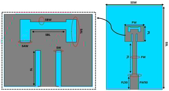
Figure 1.
Single element of the proposed system.
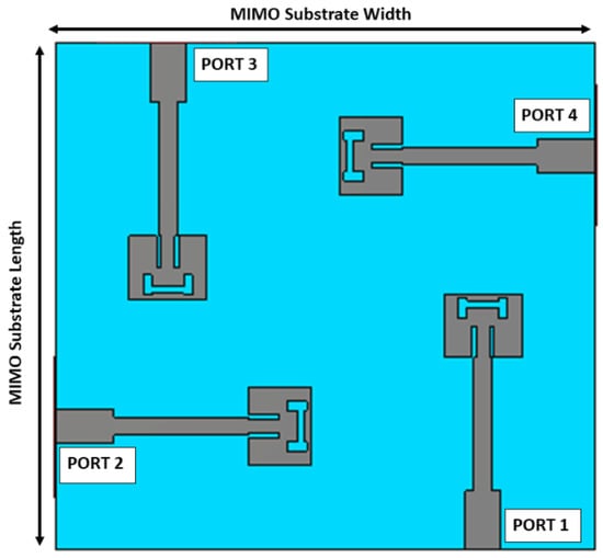
Figure 2.
Proposed four-port MIMO antenna configuration.

Table 1.
Design parameters of the system.
3. Results and Discussions
Mutual coupling between antenna elements not only degrades the system’s performance but also affects sub-systems. There are several techniques available in the literature to overcome mutual coupling. However, here, we have used a simple technique, i.e., we have arranged the antenna elements orthogonally as shown in Figure 2. The main purpose of such configuration is to enhance isolation without deploying traditional decoupling structures.
Figure 3 shows the simulated scattering parameters of the proposed system. Figure 3 illustrates the reflection coefficient and isolation between the ports of the proposed antenna, respectively. It can be seen that the antenna is radiating in two different mmwave frequencies, i.e., 28 GHz and 38 GHz, with 840 MHz and 1280 MHz bandwidth, respectively. Moreover, the proposed antenna has reflection coefficients of −18 and −20 GHz dB at 28 and 38 GHz respectively.
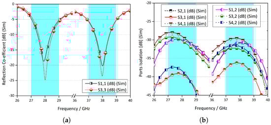
Figure 3.
Scattering parameters (a) reflections at the ports. (b) Coupling among the ports.
Parametric Analysis
One of the aims of this work is to resonate with the system at two different frequencies, i.e., 28 GHz and 38 GHz. To achieve this, a detailed analysis was structured to understand the behavior of width, length, and position of each slot on a patch. Here, we are presenting one of those studies where parametric adjustment of the slots are studied to get the desired resonance. Figure 4 shows the change in reflection coefficient of the antenna-1, when the length and width of the H-shaped slot are varied. In Figure 4a, the width of slot A is varied between 0.3 mm to 0.5 mm with a step size of 0.05 mm. Similarly, in Figure 4b, the length of slot B is changed from 0.2 mm to 0.4 mm with an increase of 0.05 mm. It can be observed from Figure 4 that by changing or varying the width of the vertical slot, the resonant frequency shifted left and as a result desired resonance is lost. In summary, the response of the antenna is sensitive to the width and length of the slot. It is observed that the second resonance is more sensitive as compared to the first resonance.
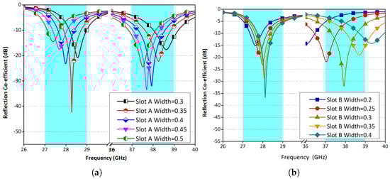
Figure 4.
Reflection Coefficient against frequency (a) SAW (b) SBW.
4. Fabrication and Measurement
The proposed system is designed and simulated in a full-wave electromagnetic wave software Computer Simulation Technology (CST), fabricated using LPKF D104 milling machine, and measured using R&SZNA67 vector network analyzer. Figure 5 and Figure 6 show the fabricated prototype and measurement setup for the proposed system. Please note that, to measure different scattering parameters at a port, other ports are terminated with a 50 match load. The radiation characteristics of the system are measured in an anechoic chamber for various azimuthal and elevation angles as shown in Figure 6.
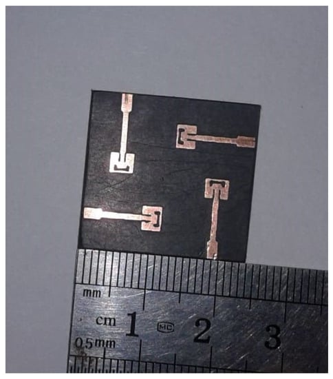
Figure 5.
Fabricated prototype of proposed MIMO antenna system.
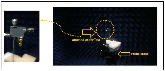
Figure 6.
Antenna measurement setup.
The measured s-parameters are shown in Figure 7. In Figure 7a, reflections at ports 1 and 3 are shown, while coupling among different ports is illustrated in Figure 7b. It is observed that the minimum isolation between the radiating elements is around 28 dB. Moreover, very good coherence and agreement are observed between the experimental and the simulated computed results.
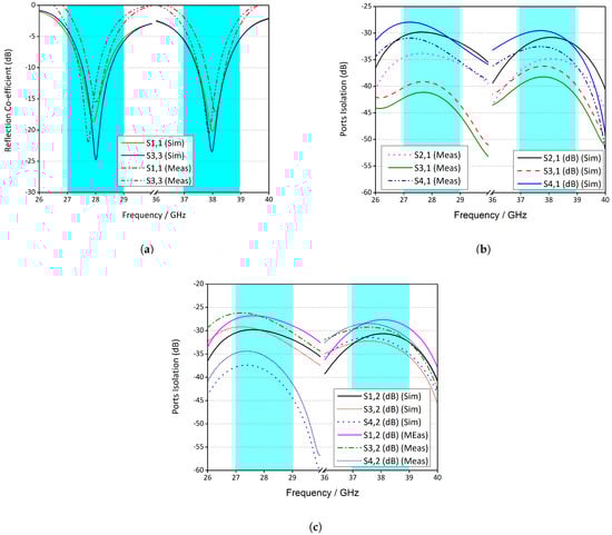
Figure 7.
Measured and simulated S-parameters of proposed antenna (a) reflection coefficient (b) ports isolation Ant 1. (c) ports isolation Ant 2.
4.1. Radiation Patterns
The far-field characteristics of the proposed system are illustrated in Figure 8. It is observed that for both bands, fields at and are highly directive and focused. It is also noted that both simulated and measured results are in good agreement with slight variations which can be attributed to human errors during fabrication and cable losses. The main lobe direction of antenna 1 for both resonating frequencies are at around for . On the other hand, for the same antenna, for , the 28 GHz has the main lobe in the and for 38 GHz, the main lobe is also in the same direction with a side lobe of comparable magnitude in . Similar, conclusions can be made for antenna 3 as well.
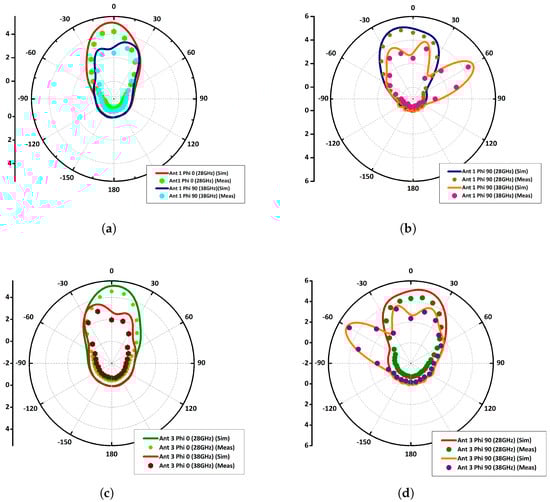
Figure 8.
Radiation patterns of proposed dual band antenna: (a) Ant 1 (b) Ant 1 (c) Ant 3 (d) Ant 3 .
4.2. MIMO Parameters
The maximum gain obtained from the proposed MIMO antenna was 6.9 dBi and 7.5 dBi at 28 GHz and 38 GHz, respectively. The measured and simulated gain obtained in Figure 9a shows that the proposed MIMO antenna may be a potential candidate for mmwave systems. The ECC levels of the antenna are very low as shown in Figure 9b which were obtained through S-parameters using Equation (1). Please note that, low ECC levels indicate that the antennas are well isolated and therefore, we can easily conclude that our proposed dual-band mmwave MIMO antenna system is highly isolated without using any decoupling structure and/or any other traditional techniques.
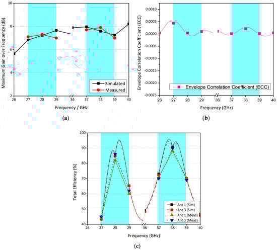
Figure 9.
MIMO Performance Parameters of the proposed MIMO antenna: (a) gain over frequency (b) ECC (c) antenna efficiencies.
The simulated and measured efficiencies are also presented and it is found that the efficiencies at the resonance frequencies are 84% and 85% at 28 GHz and 88% and 89% at 38 GHz for antenna 1 and antenna 3, respectively as shown in Figure 9c. It is reasonable to say that the ECC levels were low, therefore high efficiencies are obtained. Table 2 below shows the performance comparison of the proposed system with state-of-the-art published literature and/or other systems. From comparison, one can conclude that the proposed antenna has more advantages and better performance characteristics overall as compared to the other available candidates.
Table 2.
Performance comparison of the proposed MIMO antenna system.
5. Conclusions
In this paper, a self-decoupled compact dual-band mmave MIMO antenna system is presented. This system is consists of four radiating elements, resonating at 28 GHz and 38 GHz. Without using the traditional decoupling structures and/or techniques, we have obtained isolation of more than 28 dB among the elements. Moreover, our method simplifies the system design as well. Results obtained from simulations and experiments have very good agreement. The system results in better total efficiencies of greater than 80%. The simulated and measured values of the envelope correlation coefficient between the antenna elements are below 0.001, which can also be validated from its radiation patterns. Thus, the proposed MIMO design can be a better candidate for future next-generation mm-wave wireless applications with the additional advantages of better isolation, simple structure, compactness, and better radiation characteristics along with diversity performances.
Author Contributions
Conceptualization, K.R. and S.H.K.; methodology, D.A.S. and K.R.; software, S.H.K.; validation, A.W., F.T. and R.R.; formal analysis, D.A.S.; investigation, S.H.K.; resources, A.A.; data curation, A.A.; writing—original draft preparation, K.R., A.A. and S.H.K.; writing—review and editing, A.W. and D.A.S.; visualization, K.R.; supervision, A.W.; project administration, R.R.; funding acquisition, F.T. All authors have read and agreed to the published version of the manuscript.
Funding
This work received no external funding.
Data Availability Statement
All the data are included in the article.
Conflicts of Interest
The authors declare no conflict of interest.
References
- Yang, Q.; Gao, S.; Luo, Q.; Wen, L.; Ban, Y.L.; Ren, X.; Wu, J.; Yang, X.; Liu, Y. Millimeter-wave dual-polarized differentially fed 2-D multibeam patch antenna array. IEEE Trans. Antennas Propag. 2020, 68, 7007–7016. [Google Scholar] [CrossRef]
- Park, S.J.; Shin, D.H.; Park, S.O. Low side-lobe substrate-integrated-waveguide antenna array using broadband unequal feeding network for millimeter-wave handset device. IEEE Trans. Antennas Propag. 2015, 64, 923–932. [Google Scholar] [CrossRef]
- Sun, L.; Li, Y.; Zhang, Z.; Feng, Z. Wideband 5G MIMO antenna with integrated orthogonal-mode dual-antenna pairs for metal-rimmed smartphones. IEEE Trans. Antennas Propag. 2019, 68, 2494–2503. [Google Scholar] [CrossRef]
- Abdullah, M.; Kiani, S.H.; Iqbal, A. Eight element multiple-input multiple-output (MIMO) antenna for 5G mobile applications. IEEE Access 2019, 7, 134488–134495. [Google Scholar] [CrossRef]
- Wang, F.; Duan, Z.; Wang, X.; Zhou, Q.; Gong, Y. High isolation millimeter-wave wideband MIMO antenna for 5G communication. Int. J. Antennas Propag. 2019, 2019. [Google Scholar] [CrossRef]
- Kiani, S.H.; Altaf, A.; Abdullah, M.; Muhammad, F.; Shoaib, N.; Anjum, M.R.; Damaševičius, R.; Blažauskas, T. Eight element side edged framed MIMO antenna array for future 5G smart phones. Micromachines 2020, 11, 956. [Google Scholar] [CrossRef] [PubMed]
- Guo, J.; Cui, L.; Li, C.; Sun, B. Side-edge frame printed eight-port dual-band antenna array for 5G smartphone applications. IEEE Trans. Antennas Propag. 2018, 66, 7412–7417. [Google Scholar] [CrossRef]
- Zhu, Q.; Ng, K.B.; Chan, C.H.; Luk, K.M. Substrate-integrated-waveguide-fed array antenna covering 57–71 GHz band for 5G applications. IEEE Trans. Antennas Propag. 2017, 65, 6298–6306. [Google Scholar] [CrossRef]
- Ullah, H.; Tahir, F.A. A broadband wire hexagon antenna array for future 5G communications in 28 GHz band. Microw. Opt. Technol. Lett. 2019, 61, 696–701. [Google Scholar] [CrossRef]
- Ullah, H.; Tahir, F.A. A Novel Snowflake Fractal Antenna for Dual-Beam Applications in 28 GHz Band. IEEE Access 2020, 8, 19873–19879. [Google Scholar] [CrossRef]
- Alsariera, H.; Zakaria, Z.; Isa, A.A.M. A broadband p-shaped circularly polarized monopole antenna with a single parasitic strip. IEEE Antennas Wirel. Propag. Lett. 2019, 18, 2194–2198. [Google Scholar] [CrossRef]
- Yang, B.; Yu, Z.; Dong, Y.; Zhou, J.; Hong, W. Compact tapered slot antenna array for 5G millimeter-wave massive MIMO systems. IEEE Trans. Antennas Propag. 2017, 65, 6721–6727. [Google Scholar] [CrossRef]
- Kumar, C.; Pasha, M.I.; Guha, D. Defected ground structure integrated microstrip array antenna for improved radiation properties. IEEE Antennas Wirel. Propag. Lett. 2016, 16, 310–312. [Google Scholar] [CrossRef]
- Ren, Z.; Zhao, A. Dual-band MIMO antenna with compact self-decoupled antenna pairs for 5G mobile applications. IEEE Access 2019, 7, 82288–82296. [Google Scholar] [CrossRef]
- Sui, J.; Wu, K.L. A Self-Decoupled Antenna Array Using Inductive and Capacitive Couplings Cancellation. IEEE Trans. Antennas Propag. 2020, 68, 5289–5296. [Google Scholar] [CrossRef]
- Khalily, M.; Tafazolli, R.; Rahman, T.; Kamarudin, M. Design of phased arrays of series-fed patch antennas with reduced number of the controllers for 28-GHz mm-wave applications. IEEE Antennas Wirel. Propag. Lett. 2015, 15, 1305–1308. [Google Scholar] [CrossRef]
- Saleem, R.; Bilal, M.; Bajwa, K.; Shafique, M. Eight-element UWB-MIMO array with three distinct isolation mechanisms. Electron. Lett. 2015, 51, 311–313. [Google Scholar] [CrossRef]
- Jiang, W.; Liu, B.; Cui, Y.; Hu, W. High-isolation eight-element MIMO array for 5G smartphone applications. IEEE Access 2019, 7, 34104–34112. [Google Scholar] [CrossRef]
- Soltani, S.; Murch, R.D. A compact planar printed MIMO antenna design. IEEE Trans. Antennas Propag. 2015, 63, 1140–1149. [Google Scholar] [CrossRef]
- Wong, K.L.; Lu, J.Y. 3.6-GHz 10-antenna array for MIMO operation in the smartphone. Microw. Opt. Technol. Lett. 2015, 57, 1699–1704. [Google Scholar] [CrossRef]
- Li, M.Y.; Ban, Y.L.; Xu, Z.Q.; Wu, G.; Kang, K.; Yu, Z.F. Eight-port orthogonally dual-polarized antenna array for 5G smartphone applications. IEEE Trans. Antennas Propag. 2016, 64, 3820–3830. [Google Scholar] [CrossRef]
- Wang, H.; Liu, L.; Zhang, Z.; Feng, Z. Wideband tri-port MIMO antenna with compact size and directional radiation pattern. Electron. Lett. 2014, 50, 1261–1262. [Google Scholar] [CrossRef]
- Wang, H.; Liu, L.; Zhang, Z.; Li, Y.; Feng, Z. Ultra-compact three-port MIMO antenna with high isolation and directional radiation patterns. IEEE Antennas Wirel. Propag. Lett. 2014, 13, 1545–1548. [Google Scholar] [CrossRef]
- Al Abbas, E.; Ikram, M.; Mobashsher, A.T.; Abbosh, A. MIMO antenna system for multi-band millimeter-wave 5G and wideband 4G mobile communications. IEEE Access 2019, 7, 181916–181923. [Google Scholar] [CrossRef]
- Khalid, M.; Iffat Naqvi, S.; Hussain, N.; Rahman, M.; Mirjavadi, S.S.; Khan, M.J.; Amin, Y. 4-Port MIMO antenna with defected ground structure for 5G millimeter wave applications. Electronics 2020, 9, 71. [Google Scholar] [CrossRef]
- Rahman, S.; Ren, X.C.; Altaf, A.; Irfan, M.; Abdullah, M.; Muhammad, F.; Anjum, M.R.; Mursal, S.N.F.; AlKahtani, F.S. Nature inspired MIMO antenna system for future mmWave technologies. Micromachines 2020, 11, 1083. [Google Scholar] [CrossRef] [PubMed]
- Kamal, M.M.; Yang, S.; Ren, X.C.; Altaf, A.; Kiani, S.H.; Anjum, M.R.; Iqbal, A.; Asif, M.; Saeed, S.I. Infinity Shell Shaped MIMO Antenna Array for mm-Wave 5G Applications. Electronics 2021, 10, 165. [Google Scholar] [CrossRef]
Publisher’s Note: MDPI stays neutral with regard to jurisdictional claims in published maps and institutional affiliations. |
© 2021 by the authors. Licensee MDPI, Basel, Switzerland. This article is an open access article distributed under the terms and conditions of the Creative Commons Attribution (CC BY) license (https://creativecommons.org/licenses/by/4.0/).