Article

Further Improvement of Customized Vibration Generator for Machine–Human Feedbacks with the Help of Resonant Networks

Institute of Industrial Electronics and Electrical Engineering, Riga Technical University, LV-1048 Riga, Latvia
*
Authors to whom correspondence should be addressed.
Electronics 2021, 10(8), 962; https://doi.org/10.3390/electronics10080962
Submission received: 1 December 2020 / Revised: 12 April 2021 / Accepted: 13 April 2021 / Published: 17 April 2021
(This article belongs to the Section Circuit and Signal Processing)

Abstract

:
Modern industrial, household and other equipment include sophisticated power mechanisms and complicated control solutions and require tighter human–machine–human interaction, forming the structures known as cyber–physical–human systems. Their significant parts are human–machine command links and machine–human feedbacks. Such systems are found in medicine, for example, in orthopedics, where they are important for operation and functional abilities of orthopedic devices—smart wheelchairs, verticalizers, prosthesis, rehabilitation units, etc. The mentioned feedbacks may be implemented based on the haptic perceptions that require vibration actuators. In orthopedics, such actuators can also be used for diagnostic purposes. This research brings forward the idea of the use of resonant operation of the driver of vibration actuator. The corresponding driver has been built and experimentally tested. It has been found that (1) the point of maximal current is actually defined by the resonant frequency, (2) change of the capacitance allows shifting of the point of maximal current output and (3) damping factors make the above-described effect less obvious. Further development of the proposed idea requires a comprehensive comparison of four-quadrant and two-quadrant schemes in this application and development of a real-time programmable capacitor pack consisting of several binary weighted capacitors and a commutating circuit, which is installable to these schemes.

1. Introduction

Nowadays, the interaction of more and more sophisticated power mechanisms, rapidly developing control solutions and human beings through advanced communications has become incredibly tight, forming structures known as cyber–physical–human systems [1], which are a kind of cyber–physical system in general, with the systems linking the physical and computer worlds [2]. Quite a lot of the examples can be mentioned, where this interaction allows telepresence—doing distant work in complicated conditions. For example, the authors of [3] describe an operation hazard dangerous environment, where the telepresence system is used to control the robot submarine in order to study the shelf of the Arctic Ocean. The authors of [4] present an application with a harmful environment, and describe the experience of using various telepresence systems in the nuclear industry. One more example of such systems [5] is operation in conditions of obstructed visibility, for instance, also telepresence systems for underwater vehicle control. In this example, the data, acquired from the system, assist the formation of augmented reality in order to avoid objects collisions. Alternatively, telepresence allows for magnifying motion or torque amplitude, as it is done in [6] for the purpose of assembling complex heavy mechanisms. Finally, an example opposite to the previous one has to be mentioned [7]. In this example, the telepresence allows for making very accurate micro-movements for microsurgery, manipulative methods that reduce such side effects such as hand tremor, erroneous sudden movements, etc.

1.1. Human–Machine and Machine–Human Interaction

Each human–machine–human system has a number of information links between its components. An example of human–machine–human interaction from the medical field is a smart wheelchair with an assisting function. The concept of such an assisting-powered wheelchair is described in [8,9,10]. An assisting-powered wheelchair consists of an electrical drive (which consists of electrical machine and battery and electrical machine interface converter), battery pack, battery charger, control system, sensors, wheelchair control interface and also some kind of feedback to the user (that can be represented as visual, audible signals and also as haptic signals). In this case, the control system of the powered wheelchair, sensors, wheelchair control interface and feedback will form the human–machine–human system, or, in other words, the human-in-the-loop system. When the wheelchair user gives a command to the wheelchair control system about the start of movement, the signal from the control interface (which can be not only the most commonly used joystick, but also voice recognition systems, accelerometer control interface [11] and electroencephalography (EEG)) goes to the wheelchair control system, which coordinates the movement of the wheelchair. Additionally, the control system gathers information from various sensors, and it is needed for the system to inspect the quality of the road surface, the conditions of the wheelchair itself and the user’s condition. The wheelchair user receives feedback from the system, and this information is sent to the user via vision and hearing channels, however some amount of information can be delivered using pseudo-bionic feedback.
Figure 1 presents another example of this interaction from the medical field—a verticalizer for orthopedic and rehabilitation purposes. In this figure, the internal machine control loop, containing power actuators (in Figure 1, electrical drive—green), parameter and safety sensors (in Figure 1, proximity sensors—blue) and control system are linked with blue and green arrows. In turn, the human–machine–human interaction is shown with red and yellow arrows. This figure shows that, in general, the complete version of the human–machine–human interaction is bidirectional. Each system that includes human beings and a machine part, besides the purely internal machine regulation loops with references and parameter feedback, includes two information flows. The first evident flow that conducts information from the human-operator to the machine part provides a reference or command for the machine operation (red arrow in Figure 1). In turn, the second information flow lets the human-operator know what happens with the machine (yellow solid arrow in Figure 1). Historically, the human–machine interaction is a direct active one. It is based on simple motions (muscle force) to activate control elements—typically simple mechanical elements (joysticks, keyboards, pushbuttons, switches, etc.). The corresponding machine–human interaction utilizes the most informative human perception senses—vision and hearing. So, the elements of the machine–human link are indicators, displays, sound alarms, etc.
It must be noted that both parts are equally important for successful operation of the human–machine–human system. However, the direct machine–human information flow is not always explicit. They may look apparently absent while the situation is implicitly evaluated visually or acoustically.
The direct human–machine–human interaction requires significant attention from the operator side that retracts attention from the actual environment (yellow dashed arrow in Figure 1). It is not convenient in certain applications and, sometimes, even not possible. As an example of such application, the field of medical applications has to be mentioned. In particular, during surgery treatments, the surgeon must focus his attention on the treatment itself, rather than on the supporting equipment.
Nowadays, such kind of indirect human–machine interaction, regarded as pseudo-bionic interaction with pseudo-bionic reference means and pseudo-bionic haptic feedback, is used in various applications. The authors of [12] present their use in robotics, where the device for tele-control of heavy robots for the demolition of buildings is described. The device is equipped with a haptic feedback system for force. In [13], the use of pseudo-bionic feedback in industry is presented, where the use of haptic feedback in telecontrol systems is described for operators managing systems assembling miniature devices. The authors of [14] present the use of pseudo-bionic interaction in medicine, where an improved endoscope is used for micro-invasive surgeries on a human heart. The endoscope is equipped with a haptic force feedback system and a Cartesian manipulator.
In contrast to human–machine–human interaction, in the previously mentioned occasions, the various feedback are not mandatory. However, they dramatically improve the functional properties of the applications. For example, the authors of [15] show how the use of vibrotactile haptic feedback adds perception functions in teleoperated robotic surgery application.
It must also be noted that the definition “pseudo-bionic” lexically refers to another, more recent kind of human–machine–human interaction—purely bionic interaction—which assumes immediate reading and generation of signals from/to the central neural system. Although this approach promises the most natural “like a limb” control of the machines (including artificial limbs or prosthesis), currently, it remains at the laboratory level of research [16]. Besides, due to mandatory neurosurgery treatments (to access the neural system), the use of this approach is most reasonable in the case of prosthetics. In [17,18], the use of tactile feedback for prosthetics is described.
The considerations mentioned above allow for drawing the conclusion that nowadays, the pseudo-bionic human–machine–human interaction is the most realistic for use in various areas. In turn, the pseudo-bionic feedback is a significant part of this interaction and may be implemented based on the haptic perceptions sense.

1.2. Kinds of Haptic Perceptions Sense

There are four different sensory cell types in glabrous skin and two additional sensory cell types in hairy skin. The location of these cells is in the top 2 mm of the skin. The sensory cells in glabrous skin are named after their discoverers, while the additional cells in hairy skin have functional names [19]. The human body has a very complex mechanical structure that includes bones, soft tissues and skin. This combination makes the assessment of the external tactile impact challenging. The skin needs to recognize different types of effects on it: pressure, vibration, compression, distribution, etc. To solve this problem, there are different types of cells that perceive different types of impact. In general, sensory cells near the skin surface will react only to adjacently applied stimulations, while cells that are localized more deeply will also react to stimulations that are not applied adjacently.
The classification of a mechanoreceptor is based on the size of the receptive fields and the adaptation behavior of the receptor when a constant pressure stimulus is applied. The receptive field denotes the area on the skin on which an external mechanical stimulus will evoke a nervous impulse on a single nerve fiber. The size of the receptive field depends on the number of sensory cells that are connected to the investigated nerve fiber. Tactile mechanoreceptors exhibit either small (normally indicated with I) or large receptive fields (indicated with II). The adaptation behavior is classified as slowly adapting (SA) or rapidly adapting (RA). With these declarations, four mechanoreceptors can be defined, which are shown in Table 1. This nomenclature is based on a biological view. Further, nerve fiber is designated as a channel for which a signal enters the brain where the nervous system recognizes it. In Figure 2, the path of the vibratory stimulus from the skin to the central nervous system is shown.
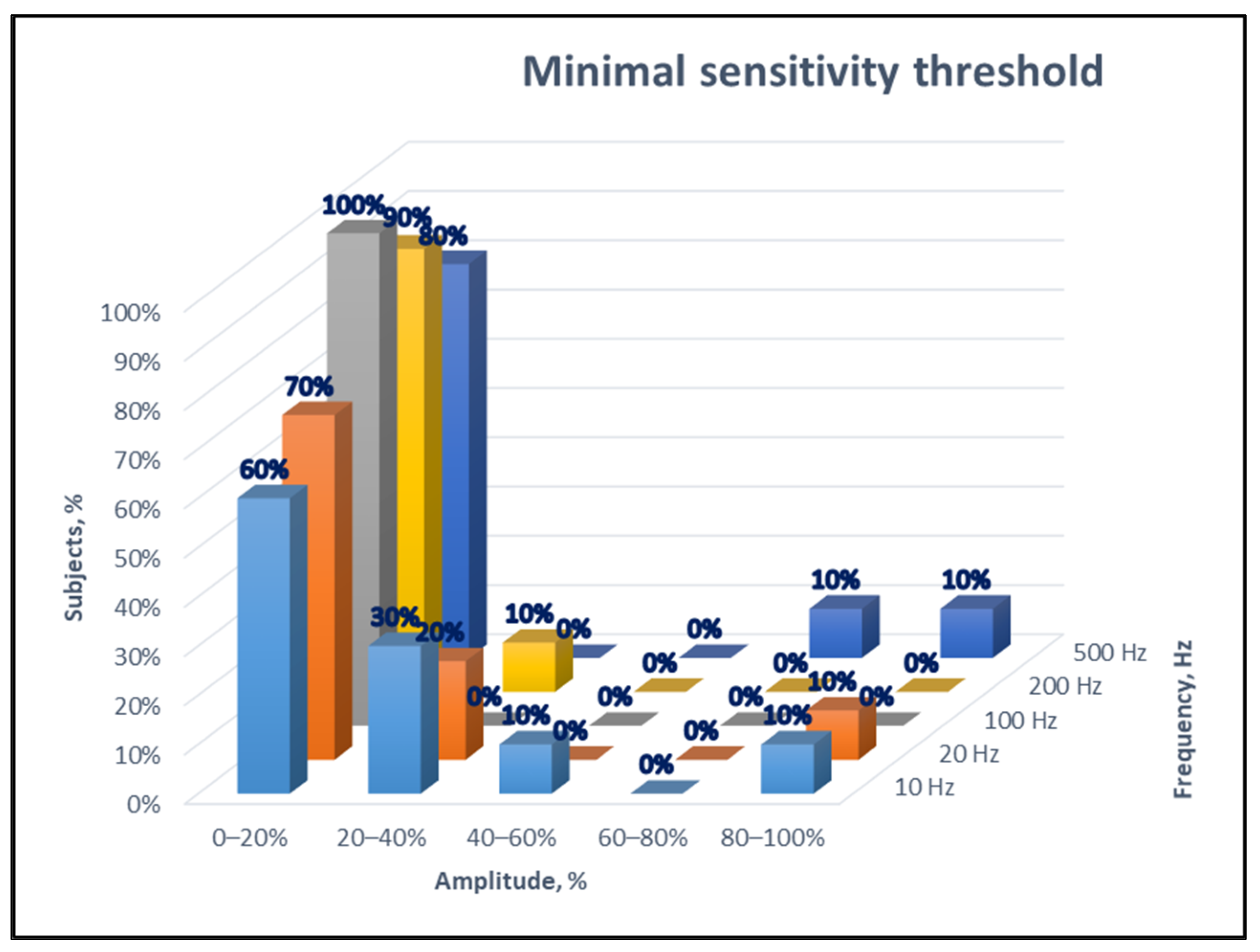
In [21], the tests of sensing the vibrations among several people aged from 20 to 40 years are presented. The minimal sensitivity threshold and the threshold of discomfort were defined for the participants of the experiment by changing the frequency and amplitude of the vibrations. Figure 3 and Figure 4 show the results of these tests, and it can be said that the sensing intensity of different people varies. Also, it can be said that with age, tactile sensing of people decreases.
The above-mentioned results lead to the conclusion that human beings are most sensitive to the vibration kind of haptic perception. In most of the occasions, it is possible to train each particular person to perceive, recognize and interpret the information coming through vibrations. However, successful implementation of this approach requires individualization of the corresponding vibration actuators.

1.3. Kinds of Vibration Actuators

The sources of vibration are mechanical movements of various objects. In the case of electrical supply, these objects are either rotary motors that drive unbalanced loads (eccentric motors) or different kinds of linear motors—electromechanical or piezoelectric.
  • Eccentric rotating mass vibration motor (ERM motor): Any motor (usually a DC motor) with a non-symmetric mass attached to the shaft [22]. The only parameter that affects both frequency and amplitude is input voltage, so the regulation of such a motor is limited.
  • Piezoelectric motors (rotating and linear) directly convert voltage oscillations into mechanical vibrations and then, due to the mechanical contact of the piezoceramic material and moving parts, into the mechanical motion. However, these motors are regarded as low-speed/voltage, high-torque/force/current motors [23,24]. Additionally, these motors need high voltage to operate at higher frequencies.
  • Voice coil motors: One challenge can be that these types of actuators usually have low active resistance (for example, 4 or 8 Ω). Therefore, lower supply voltage can be used to operate such a device. These vibration actuators are easier to regulate—the amplitude and frequency are dependent on amplitude and frequency of input voltage and can be controlled simultaneously.
  • Linear resonant actuator: these actuators have movable mass, magnet, spring and coil. Connecting the coil to the sinusoidal voltage source, it produces a magnetic field, which forces the magnet with attached mass to move, and the spring makes it move in the opposite direction. These actuators are most efficient at resonant frequencies, when mechanical resonance appears, and the efficiency critically decreases when they are working in non-resonant frequencies. Therefore, it is impossible to regulate them in a wide frequency range.
So, after the above analysis of vibration actuators, it becomes obvious that most of the existing actuators do not comply with the requirement of individualization and are rather expensive and not efficient, except for voice coil motors. Only voice coil motors have the ability to be controlled in a wide frequency region and only by using voice coil motors is it possible to regulate the amplitude of vibration.

2. Initial Proposal

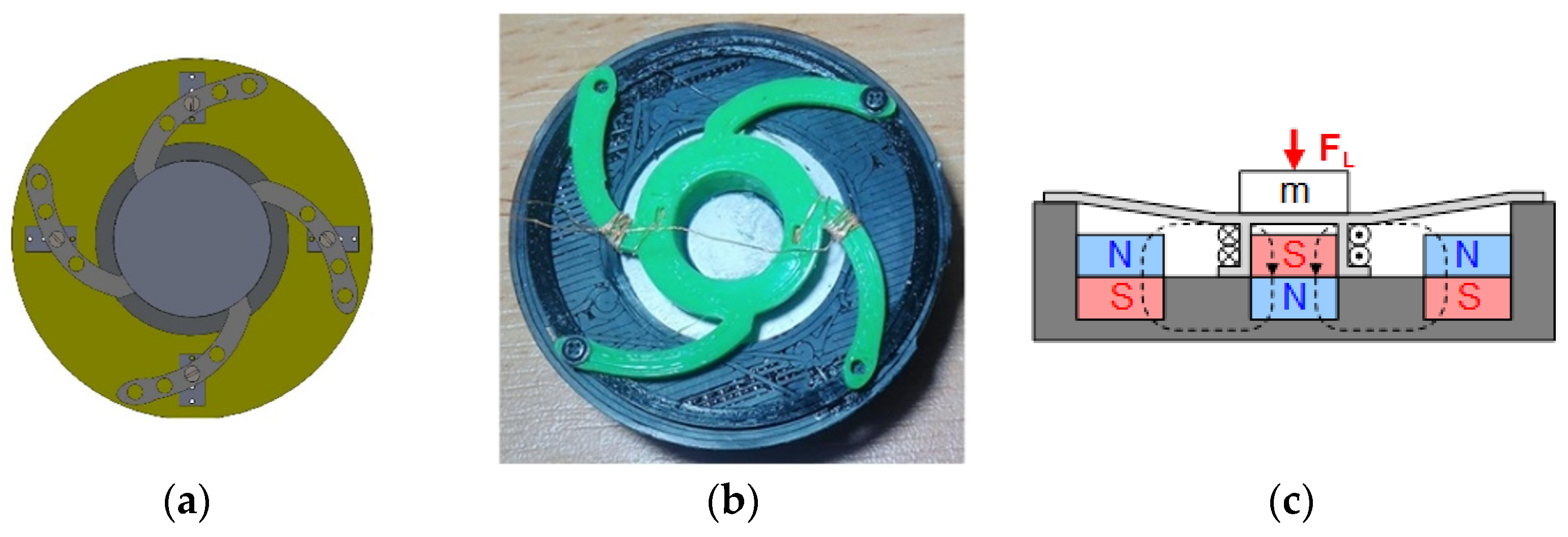
Initially, various kinds of vibration actuators were described, as reported in [18]. The proposed design (similar to the industrial voice coil motor but using non-magnetic materials and permanent magnets) is shown in Figure 5.
Figure 5a shows the structure of the initially proposed vibration generator. The variation of flexibility of membrane is important, as the mechanical parameters affect the resonant frequency—these two factors are stiffness of membrane and stiffness of the object (i.e., where the actuator is attached). It is difficult to predict the stiffness of the object, however the stiffness of the membrane can be adjusted by changing the fixation points of the membrane. Figure 5b shows the designed vibration actuator. Figure 5c shows that when applying a positive current to the coil, the coil with attached mass is attracted by Lorentz force closer to the stationary part of the vibration generator. When applying different polarity current to the coil, the Lorentz force will be pushing the coil with attached mass outside.

3. Hypotheses, Methods and Technical Assumptions

3.1. Hypotheses

As it follows from the above sections, it is reasonable to build the machine–human pseudo-bionic feedback based on haptic perceptions, in particular utilizing vibrations. On the other hand, the use of the vibration actuators that are available on the market makes the elaboration of such feedback much faster. However, the modification and optimization of their parameters is not possible. These actuators must be used as they are.
As it was previously concluded, the actuators that are available on the market and comply with the requirement of simultaneous frequency and amplitude regulation are the voice coil motors (VCM). They were originally designed for audio applications as a part of a loudspeaker, for which the membrane is supplied separately. In such applications, they operate with rather low current (corresponding to lower forces) and rather high voltage (corresponding to larger strokes). The excitation coil of these devices is wound with thinner wire and a larger number of turns, which leads to larger resistance and inductance. Besides, the active resistance of such actuators is usually standardized to 4 or 8 Ω.
This research is based on the hypothesis that the use of series resonance allows partial compensation of high impedance of VCM that, in turn, increases their power factor. In practice, it means that such actuators in the proposed operation mode will produce forces sufficient for use in pseudo-bionic feedback. In such conditions, generating vibrations at different frequencies requires moving the resonance to another point that, in turn, requires a capacitor of variable capacitance. The hypothesis, studied in this research, assumes that such capacitor can be built as a specific programmable electronic driver.

3.2. Mathemathical Considerations

The input voltage of the discussed actuator is distributed according to the following equation, representing Kirchhoff’s voltage law for the winding of the actuator:
v i n ( t ) = v R ( t ) + v L ( t ) + e ( t )
where vIN(t) is the input excitation voltage, applied to the actuator, vR(t) is voltage drop over equivalent active resistance, vL(t) is dynamic voltage add-on due to inductive inertia and e(t) is electromotive force. The first component represents real energy losses in electrical parts of the actuator, the second is the current damping element and the third represents the energy, spent in the mechanical part of the actuator or actual energy producing vibrations. Equation (1) can be presented in the space of complex numbers:
V ¯ I N = V ¯ R + V ¯ L + E ¯ = I ¯ R + I ¯ j X L + E ¯
where X L = 2 π f L and E = B l v .
Here, R is the equivalent resistance of the actuator, L is its inductance, l is the length of winding, v is the velocity of vertical movement of the winding/coil and B is the density of magnetic flux generated by permanent magnets, installed in the actuator. The parameter Bl, or force factor expressing the number of Newtons per one Ampere, is known for a particular device. The Equations (1) and (2) correspond to an equivalent circuit, shown in Figure 6a.
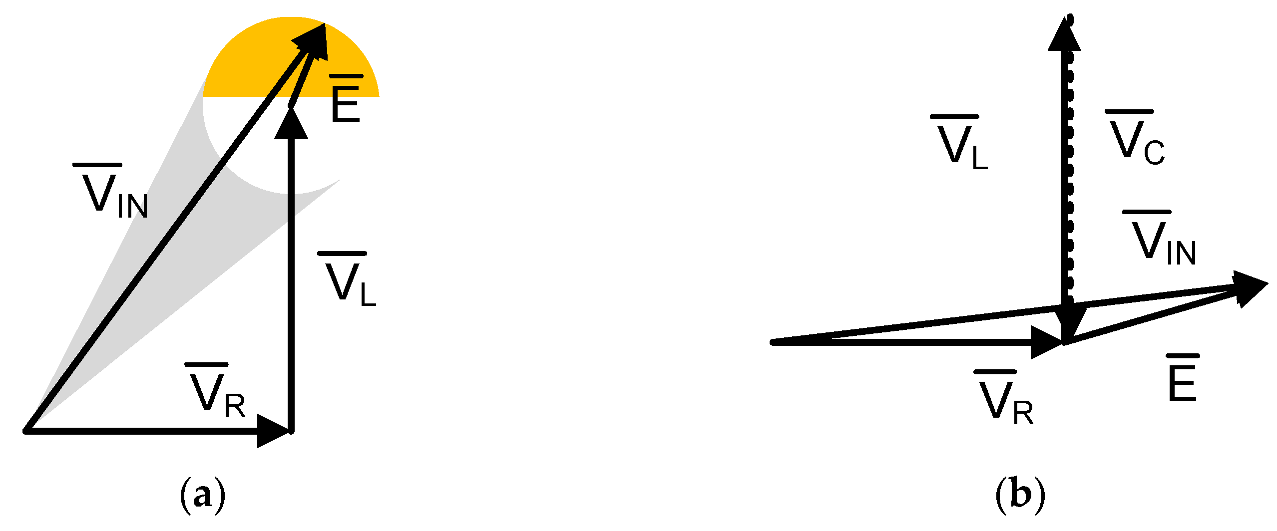
When VCM operates in an original “acoustic” mode, the distribution of voltage between the equivalent elements is unevenly shifted to the equivalent resistance and equivalent inductance. The contribution of electromotive force, E, is rather low—yellow area in Figure 6a. At such conditions, it is possible to rewrite (2) in scalar form:
V I N I Z + E = I R 2 + X L 2 + E
o r I = V I N E Z = V I N E R 2 + X L 2
Then, the Lorentz force, that is the main source of the vibrations, can be expressed as:
F L = B l I = B l V I N R 2 + X L 2 ( B l ) 2 ν R 2 + X L 2
Adding a capacitor in series with VCM, as in Figure 6b, turns Equation (1) into:
v I N ( t ) = v R ( t ) + v L ( t ) + v C ( t ) + e ( t )
Which can be expressed in the form of:
v I N ( t ) = R i ( t ) + L d i ( t ) d t + 1 C i ( t ) d t + B l v ( t )
Taking into account that for a capacitor i ( t ) = d q ( t ) d t , Equation (7) can be rewritten as:
v I N ( t ) = R i ( t ) + L d i ( t ) d t + q ( t ) C + B l v ( t )
L d i ( t ) d t + R i ( t ) = v I N q ( t ) C B l v ( t )
Capacitor added in series transforms Formula (5) into the following:
F L = B l I = B l V I N R 2 + ( X L X C ) 2 ( B l ) 2 v R 2 + ( X L X C ) 2
At the resonant frequency, f0, XL = XC, and
F L = B l I = B l V I N R ( B l ) 2 v R
Equations (10) and (11) show that in the resonant mode of the actuator, it is possible to reduce its current-limiting elements so that the force, developed by the actuator, increases (Figure 7b).

3.3. Technical Considerations

Running the actuator in the resonant mode assumes the fulfillment of several assumptions:
(I)
The resonance allows increasing the apparent power and force developed by the VCM actuator.
(II)
Since the inductance of the actuator is constant the resonance is to be achieved at different values of capacitance that require an adjustable capacitor.
(III)
As a part of the machine–human feedback or diagnostic system, the actuator must react quickly to new operation conditions that require not only an adjustable, but also a real-time programmable capacitor.
(IV)
The real-time programmable capacitor can be implemented on the basis of capacitor bank and commutation unit, capable of operating at high frequency and integrating into switch-mode driver of the actuator. The generalized structure of such scheme is shown in Figure 5c.
(V)
It is reasonable to distribute the capacitance between the capacitors of the bank according to the binary weighted principle.
A generalized structure of a driver for a voice coil motor with a real-time programmable capacitor is shown in Figure 6c. Generally, it is a simple H-bridge, where the half-bridges on the right-hand side of Figure 6c can be changed, and therefore, this changes the capacitor connected in series with R and L (VCM), from a non-connected capacitor to C1, then C2 and then C3. Taking into account that capacitors have different capacitances, this makes it possible to achieve different resonant frequencies in real-time without turning off the device and changing the connected capacitor.

4. Test Bench Development

In order to validate the hypothesis, a test bench was developed. A small voice coil motor (with the impedance Z = 4.63 Ω and inductance L = 0.00057 H at frequency 1 kHz) and a large voice coil motor (with impedance Z = 4.49 Ω and inductance L = 0.00029 H at frequency 1 kHz) were taken as vibration sources. In order to run the voice coil motor, a Class-D amplifier was used (PAM8403), from Diodes Incorporated. To operate the amplifier, the Analog Discovery Kit (ADK) from Digilent (National Instruments Company) was used, which is an oscilloscope and logic analyzer. ADK was connected to the PC using the UART (Universal Asynchronous Receiver-Transmitter) interface. Taking into account that during series resonance the impedance of the circuit is the lowest, then the current should have the highest value, so the main evaluation parameter is current in the resonant circuit. Additionally, taking into account that current is proportional to Lorentz force, it was awaited that the highest force that is produced by VCM will be when the frequency of the applied voltage is equal to the resonant frequency. Resonant frequency can be changed with the value of the capacitor connected in series with VCM. Additional active resistance (R = 4 Ω) was added in order to limit the current in the circuit and also to measure the current. In order to measure the acceleration of the moving part of voice coil motors, the analogue accelerometer ADXL335 was used. The schematic of the whole setup is shown in Figure 8a.
Using ADK, it is possible to generate a sinewave, which is the input signal of the amplifier, and to perform frequency analysis of the current in the resonant circuit. Figure 8b shows the setup for measurement with a small voice coil motor.
Acceleration of the moving part of VCMs was measured to calculate the Lorentz force. The output of accelerometer is voltage, so, first of all, acceleration should be calculated from measured voltage, which can be performed using Equation (12):
a s e n s = V s e n s k g
where a s e n s is acceleration, V s e n s is measured voltage, k is scale factor of accelerometer ( k = 300 mV/g) and g is gravitational constant ( g = 9.81 m/s2).
When acceleration is calculated, it is possible to calculate Lorentz force, which in this case can be calculated using Newton’s second law:
F = m a s e n s
where m is mass of the moving part of VCM. Mass of the moving part for a small VCM is 7 g (0.007 kg), and for a large VCM, is 14 g (0.014 kg).

5. Results

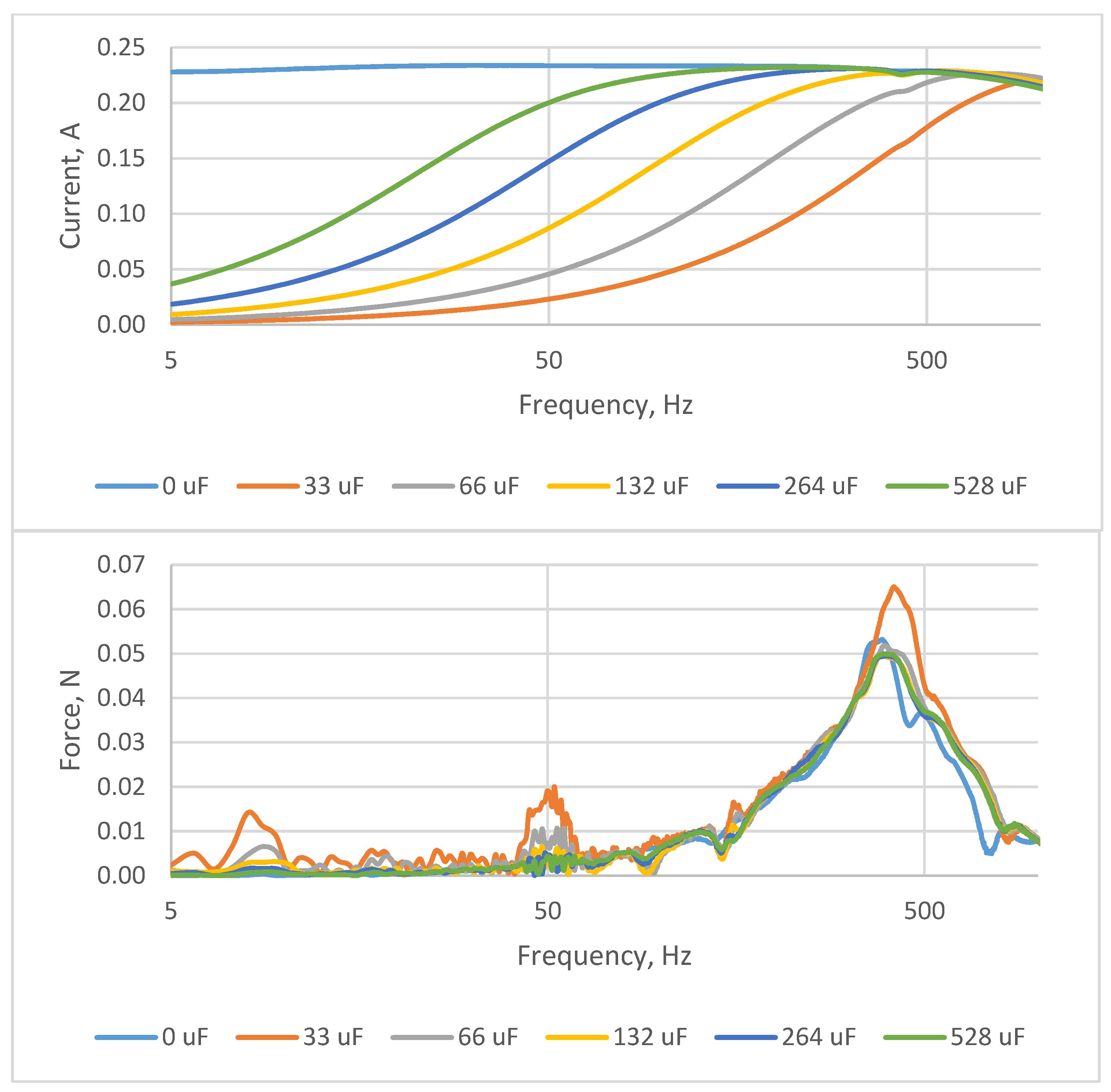
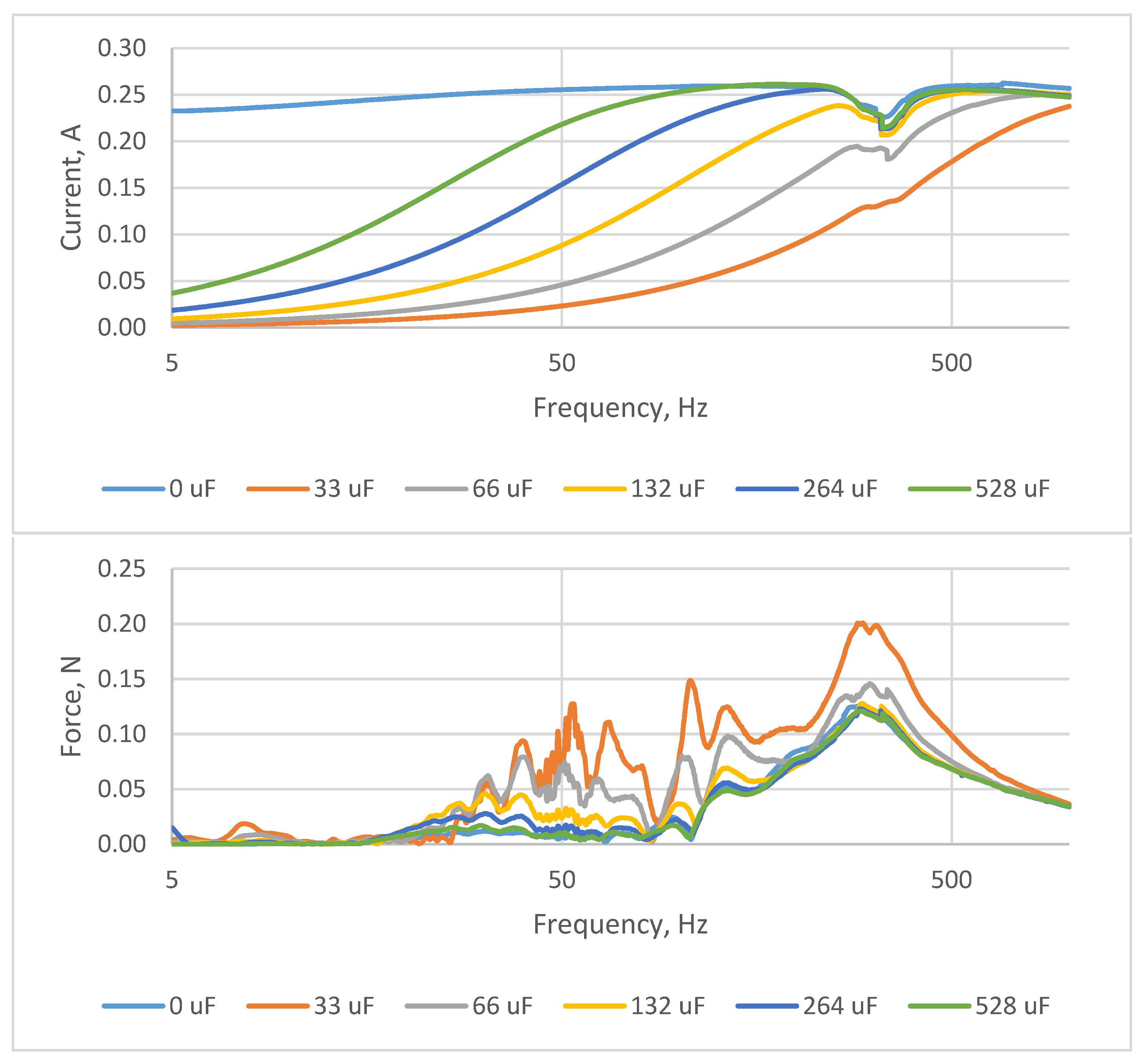
Series resonance with several capacitors with different values in a circuit with a voice coil motor was examined. The capacitances that were used were 33, 66, 132, 264 and 528 µF in order to receive different current waveforms. By adding different capacitors in series, it is possible to receive current peaks at different resonant frequencies. All capacitors were taken as ceramic, because ceramic capacitors are unipolar. Additionally, the current was measured without series capacitance in order to show the operation of VCM in the observed frequency range. The current in the resonant circuit was measured according to frequency. Modulation frequency was changed from 5 Hz to 1 kHz, with the input voltage equal to 5 V. The generalized results are shown in Figure 9 (rms current waveforms and force waveforms) for a small vibration actuator and Figure 10 (rms current waveforms and force waveforms) for a large vibration actuator.
In Figure 9 and Figure 10, the dependency between current and frequency and between force and frequency during operation of the vibration actuator (VCM) in resonant mode are shown. It can be said that the higher the value of capacitance is, the lower the resonant frequency, which can be seen from the point of maximal current. It was important to evaluate the work of VCM in resonant mode with different values of series connected capacitances because with different values of capacitance, the resonance frequency (when the inductance value is not changing) is dependent on capacitance, and therefore maximal current peaks are received at different capacitances.
However, by measuring the acceleration of vibrations of VCM during operation in resonant frequencies, the increase of current during resonance did not show any obvious advantages—it can be explained by the electrical damping factor (active resistance) and mechanical damping factor of the VCM. Despite adding different capacitances in series with VCM, the largest force is achieved at approximately one frequency (approximately 350 Hz for small VCM and approximately 300 Hz for large VCM).
In addition, there was a decrease in current in the case with a large VCM at a frequency of 345 Hz, and it is seen with all capacitances connected (less pronounced in the case with 33 µF), and can be explained by an additional resonant point that appeared because of parasitic elements, as well as because of mechanical damping factors of the large VCM.
Taking into account that in order to provide such large capacitances, as were used in the experimental section, and that in order to achieve resonance, ceramic capacitors have to be used, the idea of operating VCM in resonant mode seems to be less practically implementable.

6. Discussion and Conclusions

The data measured during experimental verification of the above hypothesis of resonant operation with different values of series capacitance generally confirmed the idea of maximal current output at resonant frequency. It is possible to split this generalized conclusion into several, more particular, statements:
(1)
The point of maximal current output is defined by the resonant frequency that occurs at equality of inductive resistance of the actuator and capacitive resistance of the attached capacitor unit XL = XC.
(2)
Changing of the capacitance of the capacitor connected in series with the actuator allows shifting of the point of maximal current output.
(3)
The electrical damping factor (active resistance) and the mechanical damping factor of the actuator make the above-described effect less obvious, but do not reduce its importance.
(4)
The capacitances of the applied capacitors are significant, which makes the hypothesis less practically implementable.
(5)
A comprehensive comparison of four-quadrant and two-quadrant schemes is required. The use of a four-quadrant converter (full transistor bridge) requires bipolar capacitors, as well as a higher number of transistors and their drivers; in turn, two-quadrant converters may require more powerful transistors and they may be less compatible with adjustable capacitors packs.
Future works can be concentrated on:
(1)
Development of a two-quadrant converter with bipolar current and unipolar voltage that would allow the use of electrolytic capacitors that would facilitate the development of the driver.
(2)
Development of a real-time programmable capacitor pack that consists of several binary weighted capacitors and a commutating circuit and its integration into the previously developed two-quadrant converter.

Author Contributions

Conceptualization, A.B., I.G. and M.V.; Methodology, A.B., I.G. and M.V.; Software, M.V.; Validation, A.B.; Formal Analysis, A.B., I.G. and M.V.; Investigation, A.B.; Resources, A.B., I.G. and M.V.; Data Curation, A.B.; Writing-Original Draft Preparation, A.B., I.G. and M.V.; Writing-Review & Editing, A.B.; Visualization, A.B. and M.V.; Supervision, I.G.; Project Administration, I.G.; Funding Acquisition, I.G. All authors have read and agreed to the published version of the manuscript.

Funding

This publication was supported by the European Regional Development Fund (ERDF) within the contract Nr. 1.1.1.1/16/A/147 “Research and Development of Electrical, Information and Material Technologies for Low-Speed Rehabilitation Vehicles for Disabled People”, in association with Cross-Platform Research Program 2020 of Riga Technical University within the contract ZI-2020/2 “Development of Orthopedic Rehabilitation Power-Assist Vehicles and Research of their Cyber-Physical Models”, and the joint found of Riga Technical University and Riga Stradiņš University within the contract RTU/RSU-19 “Research and Development of Pseudo-Bionic Feedbacks and Diagnostics Systems for Prosthetic and Rehabilitation Devices”.

Conflicts of Interest

The authors declare no conflict of interest

References

  1. Sowe, S.K.; Simmon, E.; Zettsu, K.; De Vaulx, F.; Bojanova, I. Cyber-Physical-Human Systems: Putting People in the Loop. IT Prof. 2016, 18, 10–13. [Google Scholar] [CrossRef] [PubMed] [Green Version]
  2. Serpanos, D. The Cyber-Physical Systems Revolution. Computer 2018, 51, 70–73. [Google Scholar] [CrossRef]
  3. Stoker, C.; Burch, D.; Hine, B.; Barry, J. Antarctic undersea exploration using a robotic submarine with a telepresence user interface. IEEE Expert 1995, 10, 14–23. [Google Scholar] [CrossRef]
  4. Iborra, A.; Pastor, J.; Alvarez, B.; Fernandez, C.; Merono, J.F. Robots in radioactive environments. IEEE Robot. Autom. Mag. 2003, 10, 12–22. [Google Scholar] [CrossRef]
  5. Utsumi, M.; Hirabayashi, T.; Yoshie, M. Development for teleoperation underwater grasping system in unclear environment. In Proceedings of the 2002 Interntional Symposium on Underwater Technology (Cat. No.02EX556), Tokyo, Japan, 19 April 2002; pp. 349–353. [Google Scholar]
  6. Radi, M.; Nitsch, V. Telepresence in Industrial Applications: Implementation Issues for Assembly Tasks. Presence Teleoperators Virtual Environ. 2010, 19, 415–429. [Google Scholar] [CrossRef]
  7. Hagn, U.; Ortmaier, T.; Konietschke, R.; Kubler, B.; Seibold, U.; Tobergte, A.; Nickl, M.; Jorg, S.; Hirzinger, G. Telemanipulator for remote minimally invasive surgery. IEEE Robot. Autom. Mag. 2008, 15, 28–38. [Google Scholar] [CrossRef]
  8. Vorobyov, M.; Galkin, I. Concept of cost-effective power-assisted wheelchair: Human-in-the-loop subsystem. In Proceedings of the 2017 5th IEEE Workshop on Advances in Information, Electronic and Electrical Engineering (AIEEE), Riga, Latvia, 24–25 November 2017. [Google Scholar]
  9. Vitols, K.; Podgornovs, A. Concept of cost-effective power-assist wheelchair’s electrical subsystem. In Proceedings of the 2017 5th IEEE Workshop on Advances in Information, Electronic and Electrical Engineering (AIEEE), Riga, Latvia, 24–25 November 2017. [Google Scholar]
  10. Galkin, I.; Podgornovs, A.; Blinov, A.; Vitols, K.; Vorobyov, M.; Kosenko, R. Consideretions on Cost effective power assisted wheelchair subsystems. Electr. Control Commun. Eng. 2018, 14, 71–80. [Google Scholar] [CrossRef] [Green Version]
  11. Bubovich, A.; Vorobyov, M.; Nikonorov, D.; Galkin, I. Evaluation of Accelerometer Control Interface with Powered Wheelchair. In Proceedings of the 2018 20th European Conference on Power Electronics and Applications (EPE’18 ECCE Europe), Riga, Latvia, 17–21 September 2018; pp. P.1–P.9. [Google Scholar]
  12. Jacinto-Villegas, J.M.; Satler, M.; Filippeschi, A.; Bergamasco, M.; Ragaglia, M.; Argiolas, A.; Niccolini, M.; Avizzano, C.A. A Novel Wearable Haptic Controller for Teleoperating Robotic Platforms. IEEE Robot. Autom. Lett. 2017, 2, 2072–2079. [Google Scholar] [CrossRef]
  13. Bolopion, A.; Régnier, S. A Review of Haptic Feedback Teleoperation Systems for Micromanipulation and Microassembly. IEEE Trans. Autom. Sci. Eng. 2013, 10, 496–502. [Google Scholar] [CrossRef] [Green Version]
  14. Mayer, H.; Nagy, I.; Knoll, A.; Braun, E.U.; Bauernschmitt, R.; Lange, R. Haptic Feedback in a Telepresence System for Endoscopic Heart Surgery. Presence: Teleoperators Virtual Environ. 2007, 16, 459–470. [Google Scholar] [CrossRef] [Green Version]
  15. Pacchierotti, C.; Prattichizzo, D.; Kuchenbecker, K.J. Cutaneous Feedback of Fingertip Deformation and Vibration for Palpation in Robotic Surgery. IEEE Trans. Biomed. Eng. 2015, 63, 278–287. [Google Scholar] [CrossRef] [PubMed]
  16. Edwards, J. Signal Processing Powers Next-Generation Prosthetics: Researchers Investigate Techniques That Enable Artificial Limbs to Behave More Like Their Natural Counterparts [Special Reports]. IEEE Signal Process. Mag. 2018, 35, 13–16. [Google Scholar] [CrossRef]
  17. Stephens-Fripp, B.; Mutlu, R.; Alici, G. Using Vibration Motors to Create Tactile Apparent Movement for Transradial Prosthetic Sensory Feedback. In Proceedings of the 2018 7th IEEE International Conference on Biomedical Robotics and Biomechatronics (Biorob), Enschede, The Netherlands, 26–29 August 2018; Volume 2018, pp. 213–218. [Google Scholar]
  18. Galkin, I.; Vorobyov, M.; Gainutdinovs, O.; Studers, P. Customized Vibration Generator for State of Health Monitoring of Prosthetic Implants and Pseudo-Bionic Machine–Human Feedbacks. Electronics 2019, 8, 810. [Google Scholar] [CrossRef] [Green Version]
  19. Cholewiak, R.W.; Collins, A.A. Sensory and physiological bases of touch. In Psychology of Touch; Heller, M.A., Schiff, W., Eds.; Lawrence Erlbaum: London, UK, 1991; pp. 23–60. ISBN 0805807500. [Google Scholar]
  20. Vinet, L.; Zhedanov, A. Engineering Haptic Devices; Springer: London, UK, 2014; Volume 44. [Google Scholar]
  21. Vorobyov, M.; Bubovich, A.; Galkin, I. Initial in-the-field evaluation of wheelchair’s machine-to-human haptic feedback with 3D printed vibration actuator. In Proceedings of the 2018 IEEE Industrial Cyber-Physical Systems (ICPS), St. Petersburg, Russia, 15–18 May 2018; pp. 579–584. [Google Scholar] [CrossRef]
  22. AB-004: Understanding ERM Vibration Motor Characteristics—Precision Microdrives. Available online: https://www.precisionmicrodrives.com/content/ab-004-understanding-erm-vibration-motor-characteristics/ (accessed on 18 March 2019).
  23. Belly, C.; Porchez, T.; Bagot, M.; Claeyssen, F. Improvement of Linear and Rotative Stepping Piezo Actuators using design and control. In Proceedings of the ACTUATOR2012, 13th International Conference on New Actuators, Bremen, Germany, 18–20 June 2012; pp. 246–249. [Google Scholar]
  24. Uchino, K. Piezoelectric ultrasonic motors: Overview. Smart Mater. Struct. 1998, 7, 273–285. [Google Scholar] [CrossRef]
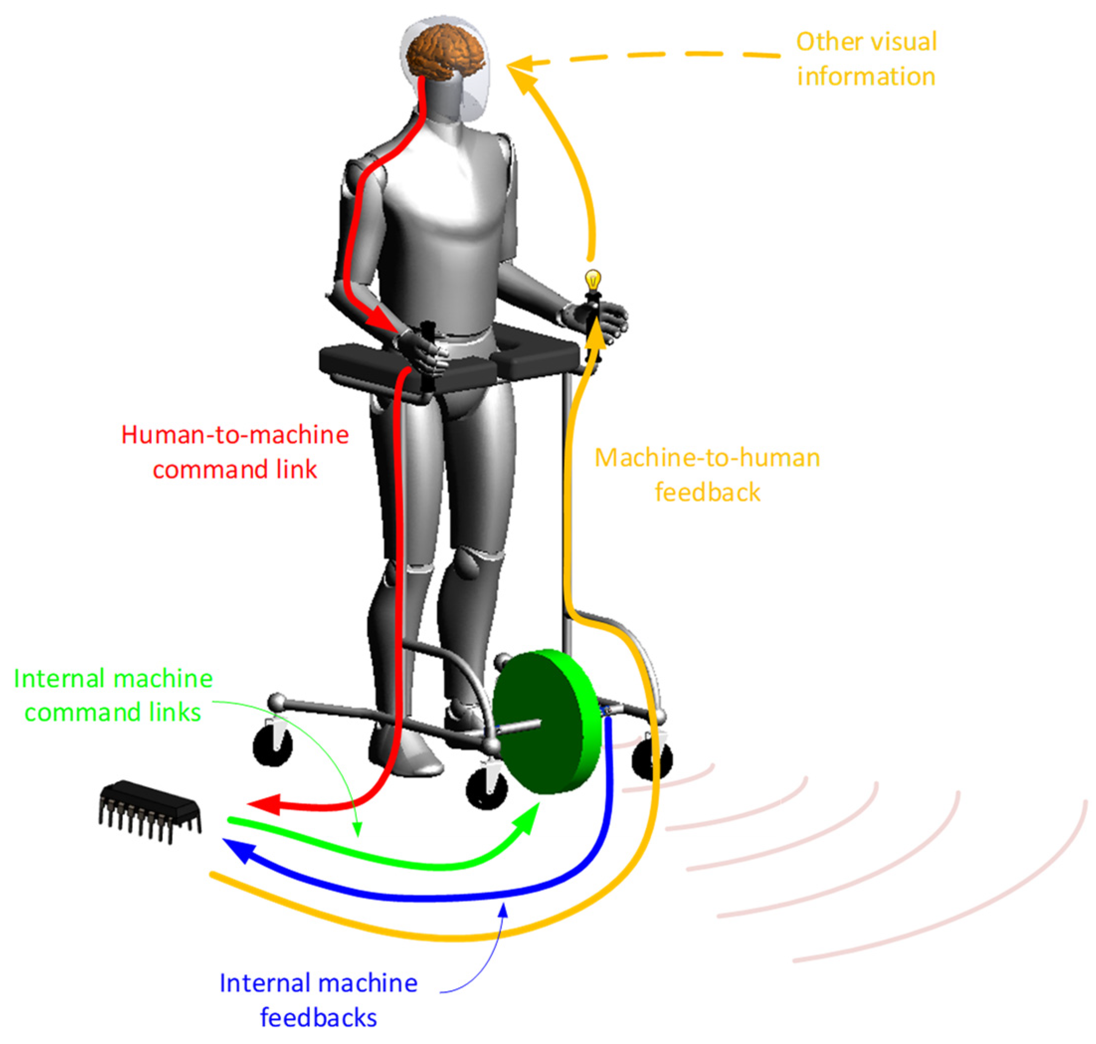
Figure 1. Human–machine–human and internal machine information flows.
Electronics 10 00962 g001
Figure 2. Block diagram of signal path.
Electronics 10 00962 g002
Figure 3. Variation of sensing intensity of various people: minimal sensitivity threshold.
Electronics 10 00962 g003
Figure 4. Variation of sensing intensity of various people: discomfort threshold.
Electronics 10 00962 g004
Figure 5. Initially proposed design of vibration actuator: (a) structure of proposed vibration generator with average flexibility, (b) design of large vibration actuator, (c) diagram of proposed vibration generator—attracting Lorentz force.
Electronics 10 00962 g005
Figure 6. Structure of the proposed driver for the vibration generator: (a) equivalent circuit, (b) equivalent resonant circuit, (c) generalized driver.
Electronics 10 00962 g006aElectronics 10 00962 g006b
Figure 7. Vector diagrams: (a) original actuator mode, (b) resonant mode.
Electronics 10 00962 g007
Figure 8. Test bench for small voice coil motor testing: (a) schematic, (b) setup for measurement with small coil motor.
Electronics 10 00962 g008
Figure 9. Measured current and force in resonant circuit depending on frequency with different capacitors with a small VCM.
Electronics 10 00962 g009
Figure 10. Measured current and force in resonant circuit depending on frequency with different capacitors with the large VCM.
Electronics 10 00962 g010
Table 1. Tactile mechanoreceptors [20].
Receptor TypeSensory CellSize (mm2)BoundaryVibration
FreQuency Filling Gap
SA-IMerkel disk7–12DistinctSteady state–20 Hz
SA-IIRuffini endings50–75DiffuseSteady state–50 Hz
RA-IMeissner corpuscle7–19Distinct10–50 Hz
RA-IIPacinian corpuscle100–300Diffuse40–1000 Hz
Publisher’s Note: MDPI stays neutral with regard to jurisdictional claims in published maps and institutional affiliations.