Abstract
Multiphase motors have multiple control planes, and harmonics are decoupled in different planes. Multiphase motors can improve magnetic field distribution, power density and core utilization by injecting certain harmonic currents into the harmonic planes. In the harmonic plane control process, due to the switching frequency of the inverter being limited, the ratio of the switching frequency to the current frequency (the carrier ratio) of the harmonic plane is low, the digital control delay increases, and the inverter output current contains more harmonics, which makes it difficult for the proportional-integral (PI) current controller to effectively control the d-axis and q-axis currents of the harmonic plane and thus unable to track the given values stably. Moreover, the PI current controller is relatively dependent on the motor parameters. For these reasons, a model predictive current control method with predictive error compensation is proposed. Taking a nine-phase induction motor as an example, the control voltage is calculated by the cost function and corrected by the current predictive error, which realizes the current control method at a low carrier ratio. Additionally, the robustness of the control method is analyzed after the parameters of the multiphase motor have large errors. The experimental results show that the proposed method can control the current of the harmonic plane at low carrier ratio, accurately track the harmonic current commands and attain strong robustness for the motor parameters.
1. Introduction
Due to its own characteristics, multiphase motors () mostly use a concentrated full-pitch winding structure. Higher stator harmonic current injection can improve the power density and core utilization of the multiphase motor and increase the output torque [1,2]. Hence, multiphase motor drive systems have become a feasible solution for high-power applications in recent years and are widely used in electrified traffic and energy production.
In order to ensure the rapidity and stability of the current control, the multiphase motor drive system usually uses a higher switching frequency to make the carrier ratio high enough. In this situation, the traditional PI current controller can already satisfy the control requirements. However, in high-power applications, limited by inverter switching losses and a temperature rise, the system switching frequency is often low [3]. For multiphase motors, the current frequency of the harmonic plane is a corresponding multiple of the fundamental plane. Therefore, at low switching frequencies, although the carrier ratio of the fundamental plane is sufficiently high, the carrier ratio of the harmonic plane is low. When the carrier ratio is low, the system control delay and the harmonic content of the inverter output current increase, and the current control bandwidth will also be limited, which will cause the dynamic, steady-state performance and stability of the current loop to deteriorate [4,5]. Therefore, compensation measures are required.
For the current control problems at a low carrier ratio, analysis of the stability of the current loop using a PI controller was conducted in [4], and a compensation method to increase the stable operation range of the system was proposed. Not only was the stability of the current loop at a low carrier ratio analyzed in [5], but the sampling error was also studied, and an error estimator to compensate for the sampling error was designed. However, the above two methods are relatively dependent on motor parameters. Based on the idea of zero-pole cancellation of the system, a complex vector current controller was presented in [6,7] which improved the dynamic performance of the current loop at a low switching frequency and reduced the controller’s sensitivity to the motor parameters. However, the structure of the controller was complicated, and digital realization was difficult. In [8], the three aspects of current loop decoupling, one-step time delay and parameter sensitivity were analyzed to propose a digital current regulator with active damping terms. The regulator could improve the stability of the current loop at a low carrier ratio and was less sensitive to the motor parameters, but the currents had a high ripple in the steady state.
On the other hand, due to the advantages of a simple concept, strong robustness and easy handling of multivariable control problems [9,10], predictive control has been widely used in industrial control in recent years. The work in [11,12] combined big data and deep learning technology for predictive maintenance and achieved the expected results. Therefore, model predictive control (MPC) provides another possibility to solve the current loop control problem of multiphase motors at a low carrier ratio. The more commonly used method in motor control is finite control set model predictive control (FCS-MPC) [13,14,15,16,17]. In [13,14], the normal FCS-MPC used an enumeration method to traverse the voltage vector and only selected one voltage vector as the optimal one within each control period. Although this method could improve the dynamic performance of the current in the control process, it led to a higher steady-state ripple and required a fast sampling rate. Double-vector-based and multi-vector-based schemes to improve the steady-state performance of FCS-MPC were proposed in [15,16]. However, they were more complicated in selecting voltage vectors and still required a fast sampling rate. The multiphase motor has a large number of voltage vectors, and the sampling rate at a low carrier ratio is also very low. Therefore, it is not suitable for multiphase motors, nor for low carrier ratios.
Considering the factor that there are more voltage vectors in multiphase motors, continuous control set model predictive control (CCS-MPC) is an excellent choice [18,19,20,21,22]. In [18,19,20], the normal CCS-MPC ignored the rotor position change during the control period when establishing the MPC discrete model, predicted the stator current in the future control period and calculated the optimal control voltage through the cost function, finally realizing the improvement of the dynamic and steady performance of the currents. Since the calculation of the optimal control voltage had no relation to the number of voltage vectors of the motor, [21,22] used CCS-MPC to improve the current control performance of a five-phase motor. However, none of the above CCS-MPC methods are suitable for low carrier ratios. When the carrier ratio of the harmonic plane is relatively low, the rotor position of the multiphase motor changes greatly in one control period, so the stator voltages of the harmonic plane change greatly in one control period [23], which makes it difficult for the CCS-MPC to accurately calculate the optimal control voltage, and the current control performance of the harmonic plane decreases.
This paper uses a symmetrical nine-phase induction motor as the research object. A novel general MPC method is proposed to solve the problem of deteriorated current control performance when the harmonic planes are at a low carrier ratio. Considering that it is difficult for the existing normal MPC methods to accurately calculate the optimal control voltage at a low carrier ratio, a scheme for correcting the control voltage using current prediction error is proposed. Moreover, the performance of normal PI controllers is affected by the accuracy of the motor parameters. In order to reflect the advantages in this respect, the parameter robustness of the proposed MPC method is analyzed. The innovations include a prediction error compensation scheme, robustness of the proposed MPC method for the motor parameters and application to the symmetrical nine-phase induction motor, which are meaningful to solve the current loop control problem of multiphase motors at low carrier ratios.
This study is organized into five sections. Section 2 gives the general model of the multiphase motor. Section 3 establishes the MPC discrete model with predictive error compensation. Section 4 presents the experimental setup and results. Finally, the discussion and conclusions are summarized in Section 5.
2. General Model of Multiphase Motors
The symmetrical nine-phase induction motor in this paper was fed by a two-level voltage source inverter (VSI) as shown in Figure 1, where the stator phase windings were evenly distributed in the spatial position and the two adjacent phase windings differed in space by 40 degrees in their electrical angles.
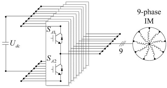
Figure 1.
Symmetrical nine-phase induction motor supplied from a two-level voltage source inverter (VSI).
Multiphase motors can be modeled as several subplanes, and different subplanes are orthogonal to each other. Taking the symmetrical nine-phase induction motor as an example, the subplanes can be represented as , , and , where is also called the fundamental plane. The Park transformation matrix T of the nine-phase induction motor can be expressed as [24]
where θ is the angle of the rotor flux, .
The nine-phase induction motor can decouple the system control variables to different subplanes by Equation (1). Hence, the voltage and torque equations of the nine-phase induction motor in can be expressed as [24,25]
where v = 1, 3, 5 and 7 for the fundamental, third, fifth and seventh harmonic planes, respectively, and are the stator voltages in , is the stator resistance, and are the stator currents in , p is the differential operator, is the synchronous angular velocity in , and are the mutual inductance and rotor inductance, respectively, is the stator inductance, , , is the electromagnetic torque, is the number of pole pairs and is the rotor flux.
The nine-phase induction motor can improve the core utilization and torque density by injecting the third, fifth and seventh harmonic currents [26]. When the switching frequency is low, since the current frequency of is v times the fundamental plane, the carrier ratio of the harmonic plane will be lower, and the PI controller can no longer effectively control the harmonic current.
When solving this problem from the perspective of MPC, take the injection of the third harmonic current as an example for analysis. The phase currents are decoupled to and by Equation (1), and MPC models need to be established in and , respectively.
3. MPC Algorithm at a Low Carrier Ratio
When the harmonic plane of the multiphase motor is at a low carrier ratio, it is difficult to achieve stable tracking of the harmonic plane currents using PI control. To solve this problem, based on the traditional MPC algorithm, a model predictive current control method of a multiphase motor with predictive error compensation is proposed. As mentioned in Section 2, when the nine-phase induction motor only injects the third harmonic current, the MPC model needs to be established in and .
3.1. Model Predivtive Current Control Discrete Model
Taking the fundamental plane as an example, when v = 1 in Equation (2), the voltage equation under the synchronous rotating coordinate system can be expressed as
In order to simplify the calculation, the coupling term between the d-axis and q-axis is treated as the forward disturbance, and the model of the d- and q-axis currents can be obtained as follows:
The forward disturbance term can be written as
where and represent the d-axis and q-axis forward disturbance in , respectively.
Using the forward Euler method to discretize Equation (5), the d-axis and q-axis currents of the next control step can be obtained as follows:
It can be seen from Equation (7) that the current models of the d-axis and q-axis have the same form. The incremental processing and state expansion of Equation (7) are rewritten into vector form [27]:
On the fundamental plane, where is the stator current in the synchronous rotating coordinate system at time k, is the current predictive value vector at the time k + 1 according to the current vector at time k, is the variation of the stator current at time k, is the current predictive variation at time k + 1 according to the current variation at time k and is the variation of the stator voltage at time k.
Using Equation (8) to predict the stator current in the next three control periods, we have
where is the current predictive value vector at time k + i, according to the current predictive value vector at time k:
.
MPC usually uses a quadratic cost function to achieve rolling optimization:
Converting the cost function into a vector form [28] yields
where
Without considering the constraints, using the cost function to solve the partial derivative of , the optimal control voltage increment can be expressed as
where .
In the actual control process, MPC calculates the optimal control voltage through the rolling horizon as follows:
where is the optimal control voltage at time k.
The expression of Equation (13) in the form of reference values and state variables is
It can be seen from Equation (14) that without considering the constraints, the optimal control voltage of the incrementally processed MPC model is obtained by multiplying the coefficient matrix KMPC1 and the integral of the prediction error. Hence, the MPC model of incremental processing is essentially feedback integral control.
Similarly, the MPC model of the third harmonic plane can be derived.
3.2. Prediction Error Compensation Scheme
In the aforementioned derivation process, the coupling terms between the d-axis and q-axis in Equation (6) are treated as forward disturbances. When the third harmonic plane of the nine-phase induction motor is in the low carrier ratio condition, the system delay is large, and the relationship between the synchronous electrical angular velocity of the third harmonic plane and the fundamental wave plane is , which leads to a large forward disturbance of Equation (6) on the third harmonic plane, the prediction error of the MPC algorithm and the calculated control voltage error increase. Therefore, it is difficult to control the currents of the third harmonic plane to track the given values. In addition, at a low carrier ratio, the number of pulse width modulation (PWM) pulses in one modulation wave period is reduced, and the inverter output current contains more harmonics, which will also cause errors in the MPC model.
In order to reduce the influence of the above factors on solving the optimal control voltage (Equation (13)) at a low carrier ratio and improve the robustness of the algorithm, the following prediction error compensation scheme was adopted.
- Correction of the optimal control voltage value
Taking the kth control period as an example, the control voltage compensation can be calculated as
where is the control voltage compensation at time k and is the compensation coefficient .
- Correction of the optimal control voltage value
The control voltage is corrected by adding the optimal control voltage obtained by Equation (13) and the control voltage compensation amount obtained by Equation (15). The corrected optimal control voltage will be used as the output of the MPC:
where is the corrected optimal control voltage at time k.
Similarly, the derivation process of the prediction error compensation scheme for the third harmonic plane is consistent with the fundamental plane.
Taking the q-axis current control in the fundamental plane as an example, the established model predictive current control block diagram is shown in Figure 2.
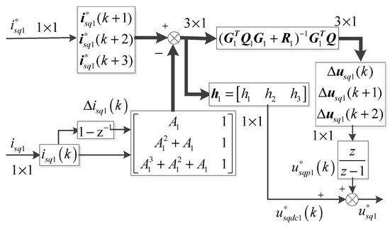
Figure 2.
Model predictive control (MPC) principle with a prediction error compensation scheme.
4. Experimental Results
In order to verify the effectiveness of the proposed algorithm, the built experimental platform is shown in Figure 3, and the experimental control block diagram is shown in Figure 4. The parameters of the nine-phase induction motor with concentrated full-pitch winding used in the experiment are shown in Table 1.
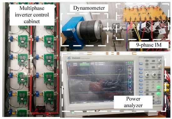
Figure 3.
Nine-phase induction motor experimental platform.
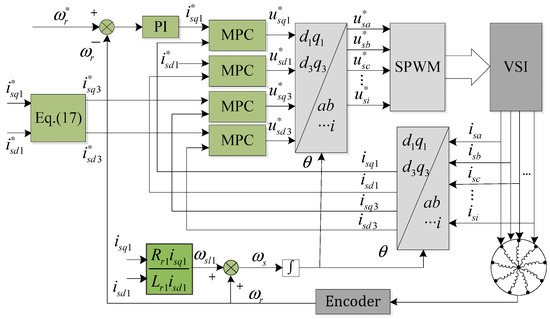
Figure 4.
Control block diagram of the nine-phase induction motor based on MPC.

Table 1.
Parameters of the nine-phase induction motor.
The inverter of the experimental platform was based on the insulated gate bipolar transistor (IGBT) module. The load was composed of a hysteresis dynamometer. The controller used TI’s TMS320F28377D signal processor. The sampling frequency and switching frequency were set to 2 kHz. As shown in Figure 4, when the nine-phase induction motor only injected the third harmonic current, the phase current could be decoupled to and through coordinate transformation for independent control. The motor torque density could be increased when the third harmonic currents were given as [29]
In the experiment, MPC used a three-step prediction horizon, and the parameters used in the algorithm were as follows:
4.1. Feasibility Experiment
In order to verify the feasibility of the proposed MPC algorithm, based on the field-oriented control (FOC) system, the control mode of MPC+FOC was adopted to make the nine-phase induction motor run at 300 r/min and 1200 r/min, respectively, and load torques of 4 Nm and 10 Nm were applied sequentially during operation. The waveforms obtained from the two experiments are shown in Figure 5 and Figure 6.
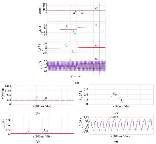
Figure 5.
Experimental waveform of model predictive control and field-oriented control (MPC+FOC) system at 300 r/min, showing (a) the whole process; (b) the speed n; (c) the current ; (d) the current ; and (e) the phase current .
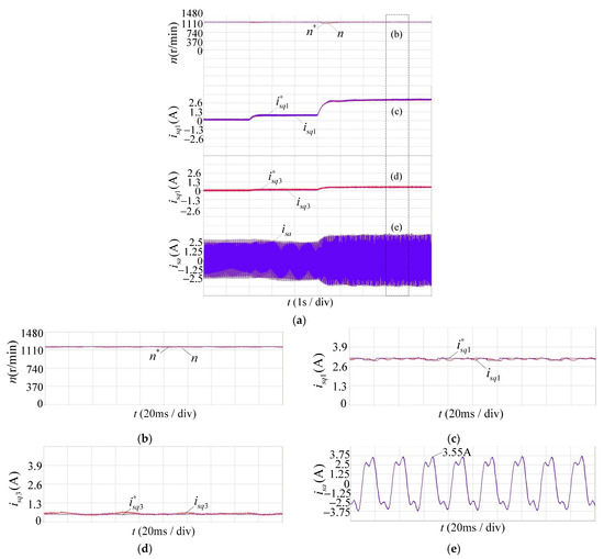
Figure 6.
Experimental waveform of the MPC + FOC system at 1200 r/min, showing (a) the whole process; (b) the speed n; (c) the current ; (d) the current ; and (e) the current .
In the figure, and n represent the given speed and actual speed, respectively, and represent the given value and actual value of the q-axis current of the fundamental wave plane, respectively, and represent the given value and actual value of the q-axis current of the third harmonic plane, respectively, and represents the phase A current.
It can be seen from Figure 5a and Figure 6a that when different load torques were applied to the motor at the two speeds, the motor speed, the currents in the fundamental plane and the harmonic plane could all track the given values without static errors. When the motor speed was at 300 r/min, the A-phase current frequency was 10.5 Hz, and the third harmonic phase current frequency was 31.5 Hz, so the fundamental plane and the third harmonic plane of the nine-phase induction motor were both at a normal carrier ratio. When the motor speed was at 1200 r/min, the A-phase current frequency was 41.1 Hz, and the third harmonic phase current frequency was 123.3 Hz, so the fundamental plane of the nine-phase induction motor was at a normal carrier ratio (48.7), and the third harmonic plane was at a low carrier ratio (16.2). These indicate that the proposed MPC algorithm could control the currents both in the fundamental plane and the harmonic plane whether at a normal carrier ratio or a low carrier ratio and track the given values without static errors.
4.2. Load Disturbance
In order to verify the control performance of the MPC algorithm in this paper at a low carrier ratio, the methods of MPC+FOC and PI+FOC were used to make the nine-phase induction motor run at 1200 r/min. In this context, the fundamental plane of the motor was at a normal carrier ratio, and the third harmonic plane was at a low carrier ratio (16.2). A load torque of 10 Nm was suddenly added during operation, and the experimental results are shown in Figure 7, Figure 8 and Figure 9.
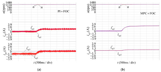
Figure 7.
Comparison of two control methods when load disturbance occurs: (a) n, and of PI+FOC; and (b) n, and of MPC+FOC.
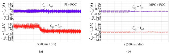
Figure 8.
Current tracking error of two control methods: (a) tracking error of and under PI+FOC; and (b) tracking error of and under MPC+FOC.
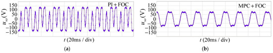
Figure 9.
Phase voltage after the filtering of two control methods with a load: (a) phase voltage under PI+FOC at a 2 KHz switching frequency; and (b) phase voltage under MPC+FOC at a 2 KHz switching frequency.
Figure 7 shows the waveforms of the speed n, fundamental plane q-axis current and third harmonic plane q-axis current when load disturbance occurred in the two control methods. Figure 8 shows the and tracking
errors when the load disturbance occurred in the two control methods.
It can be seen from Figure 7 and Figure 8 that the actual speed of both control methods could recover to the given value in a short time (0.8 s) after the disturbance occurred. When the third harmonic plane was at a low carrier ratio (16.2), the traditional PI current controller could not control to track stably due to the control delay and the decrease of the current loop control bandwidth. This effect was especially obvious when there was no load. The maximum tracking error of with no load was up to 2.17 A, and the maximum tracking error of with a load was up to 0.62 A. At the same time, the current runaway of the third harmonic plane affected the current control of the fundamental plane. Although could track the given value , there was a large oscillation and current ripple.
The proposed MPC algorithm considered the prediction error compensation, which could correct the control voltage. Under this control method, the calculation of the control voltage of the fundamental plane and the harmonic plane was more accurate, and the d-axis and q-axis currents could track the reference values. When load disturbance occurred, the actual q-axis current values of the fundamental plane and the harmonic plane could track the reference value quickly and without static error, and there was no overshoot or oscillation during the tracking process. It was shown that the current control performance of the proposed MPC algorithm at a low carrier ratio was significantly better than the traditional PI controller.
After the third harmonic currents were injected, the expected air gap flux density waveforms were a flat-top shape. Since the stator resistance and leakage reactance voltage drops were relatively small, the phase voltage waveforms and the back-EMF waveforms could be approximately regarded as the same. Additionally, since the back-EMF waveforms were the same as the air gap magnetic density waveforms, the distribution of the motor air gap flux density could be known from the phase voltage waveforms in Figure 9.
The air gap flux density was determined by the phase voltage. When no harmonics were injected, the fundamental voltage amplitude was 91 V. It can be seen from Figure 9b that after the third harmonic currents were injected through MPC, the fundamental voltage amplitude was 105 V, the phase voltage amplitude was 91.4 V, and the phase voltage was a uniform flat-top waveform. The same air gap flux density amplitude could have had a greater fundamental flux density component, thereby improving the power density and iron core utilization of the motor. However, the traditional PI controller could not control the third harmonic currents to track the given values at a low carrier ratio, resulting in distortion of the voltage and magnetic field, and the top of the phase voltage waveform in Figure 9a has a deep recess where the phase voltage amplitude is 148 V. This obviously led to the reduction of the fundamental magnetic density component at the same air gap flux density amplitude.
The quantitative comparison results are listed in Table 2, which also shows the superiority of the MPC+FOC method.
Table 2.
Quantitative comparisons between the two control methods.
Since the nine-phase induction motor injected the third harmonic current, the total harmonic distortion (THD) of MPC+FOC was 29.96%. The PI controller could not accurately control the current of the third harmonic plane, which caused the actual injected third harmonic current to be too large and much larger than the fundamental current, so the THD of PI+FOC was 187.24%. This also proves the improvement of THD using the proposed MPC method.
From the perspective of the multiphase motor system, the proposed MPC method only replaced the PI controller of the current loop in the FOC system. MPC is responsible for dealing with the current tracking problems of different subplanes in the multiphase motor system so that the output currents of the system can track the given currents without static error at a low carrier ratio and finally make the phase voltages and air gap magnetic density waveforms of the multiphase motor the expected flat-top waves. The power density and core utilization of the multiphase motor are improved.
4.3. Parameter Robustness
Traditional PI control relies on the motor parameters. When the motor parameters change, the poles of the controlled motor and the zeros of the PI controller cannot cancel each other, the PI coefficients need to be readjusted, and the motor parameter mismatch will further deteriorate the current control effect at a low carrier ratio. In order to verify the parameter robustness of the MPC algorithm at a low carrier ratio, the inductance and mutual inductance of the stator and rotor in the model were set to 0.8 times and 1.2 times the actual value, respectively. When the motor started at no load and ran stably at 1200 r/min, a load torque of 10 Nm was added suddenly. The experimental results are shown in Figure 10 and Figure 11.
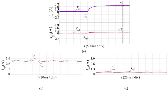
Figure 10.
The inductance is 0.8 times the actual value for (a) the whole process; (b) the current ; and (c) the current .
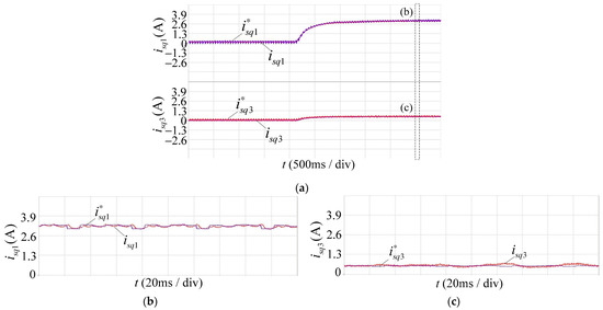
Figure 11.
The inductance is 1.2 times the actual value for (a) the whole process; (b) the current ; and (c) the current .
When the parameters had large errors, there would be errors in the calculation of the rotor flux angle, and the current prediction value would also be deviated. However, it can be seen from the experimental results that both the of the fundamental plane and the of the harmonic plane could track the given values without static errors and still have a good control effect, and there was no need to readjust the weight coefficients of the MPC algorithm. This was because the control voltage errors caused by the parameters mismatch were corrected by the prediction error compensation scheme. Therefore, the proposed MPC method had good parameter robustness at low carrier ratio conditions.
5. Discussion and Conclusions
This paper proposes a model predictive current control method for multiphase motors with predictive error compensation, which can improve the control performance of the current loop at a low carrier ratio. The MPC method is particularly suitable for high-power industrial applications where the switching frequency of inverters is limited, such as electrified traffic and energy production. We chose the three-step prediction horizon because it could greatly improve the accuracy of the cost function to calculate the optimal control voltage. Meanwhile, since the existing normal MPC method could not achieve accurate calculation of the optimal control voltage at a low carrier ratio, we proposed a solution to this problem by using current prediction errors to correct the optimal control voltage.
The experimental results showed that at different speeds of 300 r/min and 1200 r/min and different loads of 4 NM and 10 NM, the proposed MPC method could control all the currents to track the given values without static errors, showing that this MPC method could be used at a normal carrier ratio and a low carrier ratio, as well as different load conditions. When the third harmonic plane of the nine-phase induction motor was at a low carrier ratio of 16.2, the maximum static error of the third harmonic current tracking of the traditional PI controller without and with a load was 2.17 A and 0.62 A, respectively. The proposed MPC method could track the currents without static error, which fully showed that the current control performance at a low carrier ratio was significantly better than the traditional PI controller. Furthermore, our experimental results confirmed that the proposed MPC method could still have a good current control effect when the motor inductance parameters had 20% error and strong robustness to the motor parameters, which was another advantage over the PI controller. It is worth noting that the proposed MPC method does not have a good current control effect after the carrier ratio is lower than a certain value (about 16). This is because the disturbance of Equation (6) cannot be effectively compensated anymore. Therefore, how to make the MPC method effective at a lower carrier ratio is what we will study in the future, and how to quickly set the weight coefficients Q, R and h is also what we will study in the future.
Author Contributions
Conceptualization, Q.H.; methodology, Q.H.; software, Q.H. and M.K.; validation, Q.H. and M.K.; formal analysis, Q.H.; investigation, Q.H.; resources, M.K.; data curation, Q.H.; writing—original draft preparation, Q.H.; writing—review and editing, Q.H. and M.K.; visualization, Q.H. and M.K.; supervision, M.K.; project administration, M.K.; funding acquisition, M.K. All authors have read and agreed to the published version of the manuscript.
Funding
This research received no external funding.
Conflicts of Interest
The authors declare no conflict of interest.
References
- Levi, E. Multiphase Electric Machines for Variable-Speed Applications. IEEE Trans. Ind. Electron. 2008, 55, 1893–1909. [Google Scholar] [CrossRef]
- Levi, E.; Bojoi, R.; Profumo, F.; Toliyat, H.A.; Williamson, S. Multiphase induction motor drives—A technology status review. IET Elect. Power Appl. 2007, 1, 489–516. [Google Scholar] [CrossRef]
- Qi, X.; Holtz, J. Modeling and Control of Low Switching Frequency High-Performance Induction Motor Drives. IEEE Trans. Ind. Electron. 2020, 67, 4402–4410. [Google Scholar] [CrossRef]
- Altomare, A.; Guagnano, A.; Cupertino, F.; Naso, D. Discrete-Time Control of High-Speed Salient Machines. IEEE Trans. Ind. Appl. 2016, 52, 293–301. [Google Scholar] [CrossRef]
- Yim, J.; Sul, S.; Bae, B.; Patel, N.R.; Hiti, S. Modified Current Control Schemes for High-Performance Permanent-Magnet AC Drives with Low Sampling to Operating Frequency Ratio. IEEE Trans. Ind. Appl. 2009, 45, 763–771. [Google Scholar] [CrossRef]
- Bae, B.H.; Sul, S.K. A compensation method for time delay of full-digital synchronous frame current regulator of PWM AC drives. IEEE Trans. Ind. Appl. 2003, 39, 802–810. [Google Scholar] [CrossRef]
- Holtz, J.; Oikonomou, N. Fast Dynamic Control of Medium Voltage Drives Operating at Very Low Switching Frequency—An Overview. IEEE Trans. Ind. Electron. 2008, 55, 1005–1013. [Google Scholar] [CrossRef]
- Yu, A.; Wang, S.; Zhang, C.; Chai, X.; Kan, Z. Design of Digital Current Regulator for PMSM with Low Carrier Ratio. In Proceedings of the 2019 22nd International Conference on Electrical Machines and Systems (ICEMS), Harbin, China, 11–14 August 2019; pp. 1–7. [Google Scholar] [CrossRef]
- Vazquez, S.; Rodriguez, J.; Rivera, M.; Franquelo, L.G.; Norambuena, M. Model Predictive Control for Power Converters and Drives: Advances and Trends. IEEE Trans. Ind. Electron. 2017, 64, 935–947. [Google Scholar] [CrossRef]
- Sharma, S.; Aware, M.V.; Bhowate, A. Symmetrical Six-Phase Induction Motor-Based Integrated Driveline of Electric Vehicle with Predictive Control. IEEE Trans. Transp. Electrification. 2020, 6, 635–646. [Google Scholar] [CrossRef]
- De santo, A.; Galli, A.; Gravina, M.; Moscato, V.; Sperli, G. Deep Learning for HDD health assessment: An application based on LSTM. IEEE Trans. Comput. 2020, 1, 1. [Google Scholar] [CrossRef]
- Petrillo, A.; Picariello, A.; Santini, S.; Scarciello, B.; Sperlí, G. Model-based vehicular prognostics framework using Big Data architecture. Comput. Ind. 2020, 115, 103177. [Google Scholar] [CrossRef]
- Zhang, Y.; Xie, W. Low Complexity Model Predictive Control—Single Vector-Based Approach. IEEE Trans. Power Electron. 2014, 29, 5532–5541. [Google Scholar] [CrossRef]
- Vafaie, M.H.; Mirzaeian Dehkordi, B.; Moallem, P.; Kiyoumarsi, A. A New Predictive Direct Torque Control Method for Improving Both Steady-State and Transient-State Operations of the PMSM. IEEE Trans. Power Electron. 2016, 31, 3738–3753. [Google Scholar] [CrossRef]
- Zhang, Y.; Xu, D.; Huang, L. Generalized Multiple-Vector-Based Model Predictive Control for PMSM Drives. IEEE Trans. Ind. Electron. 2018, 65, 9356–9366. [Google Scholar] [CrossRef]
- Yuan, Q.; Ma, T.; Zhao, R.; Yang, Y. A General Double Vector-Based Model Predictive Current Control for the Dual Three-Phase Motors. Electronics 2020, 9, 2000. [Google Scholar] [CrossRef]
- González-Prieto, I.; Zoric, I.; Duran, M.J.; Levi, E. Constrained Model Predictive Control in Nine-Phase Induction Motor Drives. IEEE Trans. Energy Convers. 2019, 34, 1881–1889. [Google Scholar] [CrossRef]
- Zhiguo, W.; Zedong, Z.; Yongdong, L.; Guibin, L. Predictive Current Control for Three Phase Induction Machine Using Multi-Steps Prediction Horizon. Trans. China Electrotech. Soc. 2018, 33, 1975–1984. [Google Scholar]
- Favato, A.; Carlet, P.G.; Toso, F.; Bolognani, S. A Novel Formulation of Continuous Control Set MPC for Induction Motor Drives. In Proceedings of the 2019 IEEE International Electric Machines & Drives Conference (IEMDC), San Diego, CA, USA, 11–15 May 2019; pp. 2196–2202. [Google Scholar] [CrossRef]
- Li, J.; Zhang, L.; Niu, Y.; Ren, H. Model predictive control for extended Kalman filter based speed sensorless induction motor drives. In Proceedings of the 2016 IEEE Applied Power Electronics Conference and Exposition (APEC), Long Beach, CA, USA, 20–24 March 2016; pp. 2770–2775. [Google Scholar] [CrossRef]
- Martinez, J.L.R.; Arashloo, R.S.; Salehifar, M. Predictive current control of outer-rotor five-phase BLDC generators applicable for off-shore wind power plants. Electr. Power Syst. Res. 2015, 121, 260–269. [Google Scholar] [CrossRef]
- Xue, C.; Song, W.; Feng, X. Model predictive current control schemes for five-phase permanent-magnet synchronous machine based on SVPWM. In Proceedings of the 2016 IEEE 8th International Power Electronics and Motion Control Conference (IPEMC-ECCE Asia), Hefei, China, 22–26 May 2016; pp. 648–653. [Google Scholar] [CrossRef]
- Jarzebowicz, L. Impact of low switching-to-fundamental frequency ratio on predictive current control of PMSM: A simulation study. In Proceedings of the 2018 25th International Workshop on Electric Drives: Optimization in Control of Electric Drives (IWED), Moscow, Russia, 31 January–2 February 2018; pp. 1–5. [Google Scholar] [CrossRef]
- Liu, Z.; Zheng, Z.; Li, Y. Enhancing Fault-Tolerant Ability of a Nine-Phase Induction Motor Drive System Using Fuzzy Logic Current Controllers. IEEE Trans. Energy Convers. 2017, 32, 759–769. [Google Scholar] [CrossRef]
- Sun, J.; Liu, Z.; Zheng, Z.; Li, Y. An Online Global Fault-Tolerant Control Strategy for Symmetrical Multiphase Machines with Minimum Losses in Full Torque Production Range. IEEE Trans. Power Electron. 2020, 35, 2819–2830. [Google Scholar] [CrossRef]
- Da Silva, A.G.F.; de Freitas, I.S.; da Silva, S.A.; Melo, V.F.M.B.; da Paz, G.F. IFOC for a Nine-phase Induction Motor Drive with Current Harmonic Injection. In Proceedings of the 2019 IEEE 15th Brazilian Power Electronics Conference and 5th IEEE Southern Power Electronics Conference (COBEP/SPEC), Santos, Brazil, 1–4 December 2019; pp. 1–6. [Google Scholar] [CrossRef]
- Asad, B.; Hasan, K.M. Laguerre Function’s Based Model Predictive Control of Three Phase Induction Motor. Appl. Mech. Mater. 2012, 229–231, 961–967. [Google Scholar] [CrossRef]
- Wang, L. Model Predictive Control System Design and Implementation Using MATLAB®; Springer: London, UK, 2009. [Google Scholar]
- Lyra, R.O.C.; Lipo, T.A. Torque density improvement in a six-phase induction motor with third harmonic current injection. IEEE Trans. Ind. Appl. 2002, 38, 1351–1360. [Google Scholar] [CrossRef]
Publisher’s Note: MDPI stays neutral with regard to jurisdictional claims in published maps and institutional affiliations. |
© 2021 by the authors. Licensee MDPI, Basel, Switzerland. This article is an open access article distributed under the terms and conditions of the Creative Commons Attribution (CC BY) license (http://creativecommons.org/licenses/by/4.0/).