Article

Fuzzy-Based Distributed Cooperative Secondary Control with Stability Analysis for Microgrids

1
Faculty of Engineering and IT, University of Technology Sydney, Ultimo 2007, Australia
2
Faculty of Engineering, School of Electrical Engineering and Telecommunication, University of New South Wales, Sydney 2052, Australia
3
School of Electrical and Information Engineering, University of Sydney, Camperdown 2006, Australia
*
Authors to whom correspondence should be addressed.
Electronics 2021, 10(4), 399; https://doi.org/10.3390/electronics10040399
Submission received: 18 December 2020 / Revised: 2 February 2021 / Accepted: 3 February 2021 / Published: 7 February 2021
(This article belongs to the Section Power Electronics)

Abstract

:
This research suggests a novel distributed cooperative control methodology for a secondary controller in islanded microgrids (MGs). The proposed control technique not only brings back the frequency/voltage to its reference values, but also maintains precise active and reactive power-sharing among distributed generation (DG) units by means of a sparse communication system. Due to the dynamic behaviour of distributed secondary control (DSC), stability issues are a great concern for a networked MG. To address this issue, the stability analysis is undertaken systematically, utilizing the small-signal state-space linearized model of considering DSC loops and parameters. As the dynamic behaviour of DSC creates new oscillatory modes, an intelligent fuzzy logic-based parameter-tuner is proposed for enhancing the system stability. Accurate tuning of the DSC parameters can develop the functioning of the control system, which increases MG stability to a greater extent. Moreover, the performance of the offered control method is proved by conducting a widespread simulation considering several case scenarios in MATLAB/Simscape platform. The proposed control method addresses the dynamic nature of the MG by supporting the plug-and-play functionality, and working even in fault conditions. Finally, the convergence and comparison study of the offered control system is shown.

1. Introduction

A microgrid (MG) (containing of small-scale developing generators, loads, batteries and a regulatory element) is defined as a regulated small-scale power network, which can be functioned in an islanded and/or grid-connected operation mode assisting the requirement of complementary power and/or preserve a usual service [1]. Like the traditional power system, MG systems also follow the hierarchical control strategy for standardization of the MG operation and overall function. Generally, this hierarchical control system incorporates three levels, namely, primary, secondary and tertiary control layers. The traditional droop control technique considered as the most commonly used control at the primary control level because of its decentralized nature, which lessens the communication requirements [2]. However, the primary droop control shows some other shortcomings, including its frequency/voltage deviations according to load characteristics, inaccurate reactive power-sharing, and poor performance with nonlinear loads [3,4]. The secondary control level is thus introduced as a complement of primary control [2,5]. Limitations of centralized (single-point of failure) and decentralized (poor dynamic and steady-state response) control strategies have led to distributed control structures [3,6]. Recently, multiagent structures or consensus algorithms [7,8] have received increased attention for their simple control structure utilizing sparse communication systems, improved reliability and acceptable dynamic/steady-state performance [6,8,9,10]. Nevertheless, the dynamic response of the MG considering distributed secondary control (DSC) could be unexpected in regard to the system oscillation, reaction time, stability margins [10] and steady-state behaviour. Despite several advantages of distributed control, the limitations mentioned above are taken as key challenges for an islanded MG with DSC. The MG control system design should address these drawbacks in a proper way to maintain the stability and resilience of the whole network. In this light, the following issues should be considered in the design process.
There are many methods, studied for the development of the stability of the primary control [11,12,13]. Small-signal stability is now a significant issue in the reliable operation of an MG due to low-inertia and intermittent renewables [14]. Small-signal modelling is considered for the stability analysis for MGs with the decentralized droop control techniques at the primary level in most research works [11]. Authors in [15] succeeded in precise power sharing considering a consensus-based droop constant controller. Small-signal stability analysis considering DSC is studied in some recent works [7,8,10,13,16,17]. Additionally, the impact assessment of DSC parameters based on the dynamic model, the requirement of fine tuning of DSC parameters for stability enhancement, and the corresponding suitable solution (i.e., fuzzy-based controller) for that are not considered. Authors in [8] study the above issue of DSC for stability analysis but the detailed mechanism of choosing the DSC parameters for stability enhancement is not discussed. A detailed mechanism study for undesired dynamic behaviour and the probable oscillations introduced by DSC is reported in [10]. However, the use of an optimal controller for stability enhancement of the DSC leads to the system being more complex for control system design. Besides, in the majority of works, the power lines are considered to be purely inductive, which makes the models and proposed solutions inaccurate and impractical for a networked MG [18]. References [19,20,21] assume purely inductive grids used for dynamic studies of distributed secondary frequency controller (DSFC) [20] and the distributed secondary voltage controller (DSVC) [19,21]. Virtual impedance is mostly implemented into the droop control for converting the feeder impedance inductive, which will decouple the active and reactive power regulation [22,23,24,25,26,27]. Some researchers have suggested applying the virtual impedance as a means of employing precise reactive power in MGs [24,27]. Another approach in [24,28] proposed an adaptive virtual impedance for eliminating the impedance incompatibility in the feeders. Still the stability study is unresolved, and the DG units are taken into account by means of equal rating.
Apart from this, the conventional voltage-reactive power droop control results in inaccuracy in reactive power sharing with small feeder line impedances [18,29]. An improved droop control was suggested in [30], where incorrect reactive power sharing is yet noticed under clearly non-uniform line impedances. In addition, current secondary control approaches are categorized as centralized [31], decentralized [32,33,34] and distributed control [6,8,9,21,35]. This is somewhat motivated by the cooperative control concept for multiagent structures [6,8,9,32,33], letting all distributed energy resources (DERs) connect through their neighbours across local communication systems. Maximum distributed reactive power control (DRPC) techniques apply the voltage sensitivity analysis-based scheme [33,36] as per the literature for calculating the exact amount of reactive power, which each DER requires to add for confirming the system voltage maintained within allowable boundaries. Nevertheless, the sensitivity technique necessitates linearization of the power flow equations around the usual operating point, which can cause the wrong re-estimation of the necessary reactive power specifically for MG networks with low X/R ratio and high penetration of DERs. Therefore, the overall system losses are increased, which introduces a probable inconvenience on the primary distribution network including extreme requirement of reactive power.
However, another work, introduced in [37], applies predefined equal local voltage regulator functions designed for every DER in the network. This kind of method greatly suffers from one requirement, which necessitates a thorough procedure for finding optimal parameters by tuning and describing these functions. The voltage regulation may be useless or can affect an excessive quantity of reactive power flow in the scheme without accurate tuning [36]. To resolve this issue, suitable and efficient tuning is a prerequisite is significant to accomplish the system stability and have reliable operation against load change and large disturbance. Computational intelligence algorithms such as fuzzy logic (FL) [4,38,39], genetic algorithm (GA) [40,41] and particle swarm optimization (PSO) [13,42] have been commonly used to resolve difficulty of the power system. However, some deficiencies in GA performance such as the premature convergence have been recorded. On the other hand, PSO is a population based search technique deriving from models of insect swarm. In the existing works [43], intelligent techniques such as FL, PSO and GA are used to obtain optimal controller parameters. Authors proposed in [41] a non-linear and non-convex optimization problem, which too contains eigenvalues constraints. Thus, PSO is adopted to solve this problem to obtain the optimal distributed control parameters. When associated with more stochastic algorithms it has been realized that PSO necessitates less computational effort. Even though PSO has presented its potential on many aspects for resolving diverse optimization problems, it still needs significant execution time to get solutions for large-scale engineering problems [41].
Alternatively, the fuzzy logic controllers (FLCs) algorithms can tune the system constraints and outputs based on the information feed automatically to the system, which enhances the system’s simplicity and flexibility, and FLC can handle problems with imprecise and incomplete data and FLCs are cheaper to build. To reduce the complexity and enhance the controller flexibility, this paper proposed the FLC tuner for DSC. The authors in [44] introduce a DSC framework of islanded MGs. An intelligent FL based scheme is suggested for proper tuning of the consensus parameters, but only voltage regulation and reactive power sharing are taken into account [44]. Authors in [45] considered both voltage and frequency regulation of an islanded MG relied on a FLC structure. Dynamics of the scheme, i.e., plug-and-play capability, and fault occurrence, are not included. Authors in [4] proposed a novel scheme to control the reactive power nominal value of distributed generation (DG) components consistent with their involvement in reactive power sharing in islanded MG. According to the recommended method, FL is implemented to design the X/R ratio of the connecting power lines into the consensus signals in order for proper participation of DG units for precise active and reactive power sharing irrespective of the nature of feeder impedance. Although the proposed control can share the power accurately, the control level was studied for the primary control level only. In addition, the point of common coupling (PCC) bus voltage, reliant on the DSVC, essentially is being re-established to confirm nonstop action of sensitive loads. Authors in [46] offer critical bus voltage reestablishment; though, it does not concurrently preserve precise reactive power sharing among DG units. The conventional droop control technique exhibits some other limitations such as steady-state frequency deviation from the rated value, poor dynamic behaviour and high sensitivity to measurement noises [5,18,29]. Thus, conventional droop control cannot assure high accuracy of frequency control and power sharing. As a result, a secondary regulation system has been introduced to guarantee a steady frequency profile in the MG [5]. In the existing literature for frequency control and active power sharing, secondary control systems of MGs are generally classified into three groups: centralized [47], decentralized [32,48,49] and distributed [8,9,21,35,36,50,51]. The central controller for frequency restoration also faces the possibility of a single point of failure and could have trustworthiness and scalability concerns [2,8,25,31,49]. Recently, numerous DSC strategies have been stated in the literature. Most methods are based on consensus practice [4,8,9,50,51,52,53], where the agents achieve consensus by means of exchanging information over a sparse communication system. The control method described in [51] reports simply frequency restoration through a distributed averaging proportional-integral controller but requires a centralized communication configuration regardless of its decentralized execution. In [54], a DSFC scheme using linear input and output feedback was offered. The communication among neighbouring DG units is straightforward but power sharing is less focused. The authors in [21,49,52] proposed a DSC for frequency control and accurate active power sharing in islanded MGs where the voltage regulation is not taken into account. The distributed control methodologies referred to in [46,55] deal with both voltage and frequency restoration, but a comprehensive model of the MG system is a prerequisite. Authors in [56] addressed the issue of frequency restoration and active power sharing, but methods of choosing DSC parameters make the system more complex. On the other hand, DGs line, loads and MG structures are unfamiliar in reality, and the selection of controller gains are relied on the algebraic connectivity of the communication system.
However, centralized or DSC requires assistance from communication networks. Communication delay is an unavoidable and intrinsic matter for the period of the signal transmission procedure. A large communication delay can worsen the system’s dynamic behaviour, reduces the system stability margin and even causes an unstable structure [57]. Hence, it is essential to analyse the effect of communication delay on system stability, also examine the relating delay compensation technique to get a stable system [16,35]. Furthermore, inevitable noise disruptions from communication channels and the external surroundings (i.e., produced by environmental reasons, for example rain, etc.) could disturb MG’s dynamic behaviour [58]. Thus, to study the DSC problem for AC autonomous MG considering communication delay, communication link failure and noise is required. This has not been significantly or accurately reflected in a single control approach in prior research [8,21,33,35,45]. Extensive time-domain simulations considering different case studies like communication restriction, fault occurrence and plug-and-play capability considered at the same time are not taken into account in the previous research works to verify the robustness of the DSC (see all the references mentioned in this paper).
According to the literature review, it can be realized that DSC is more effective than the centralized one [3]. Due to the limited research undertaken so far, as mentioned in the literature review, a proper DSC is still needed that considers all the drawbacks in a single control strategy. To this end, motivated by the existing limitations, this paper proposes a new DSC, which has contributions from the following viewpoints:
  • A novel DSC is proposed for lossy MGs to restore frequency and voltage simultaneously while accurate active and reactive power sharing are preserved.
  • Unlike the existing consensus methods, the proposed method utilizes a proportional-integral (PI) controller at the output voltage of the inverter. Thus, voltage mismatches are reduced to a great extent.
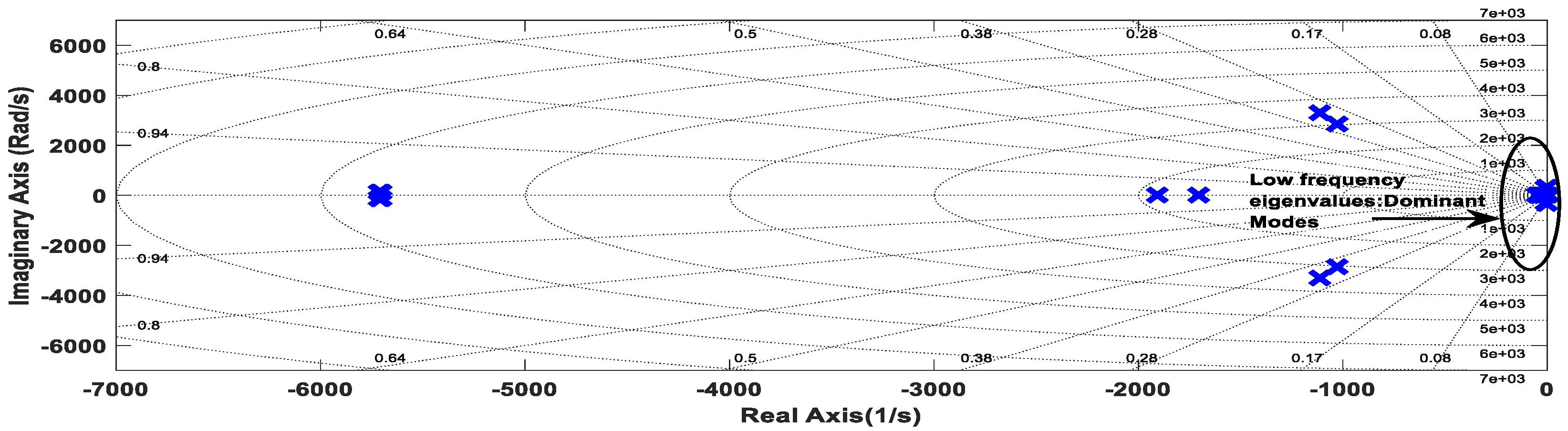
  • The small-signal stability analysis under the proposed DSC for the networked MG model is carried out in detail. Note that eigenvalue analysis for parallel-connected DGs in the MG was previously studied in many studies, but very few studies have addressed the small-signal stability analysis for a networked MG model considering DSC.
  • In most of the previous related works, other tuning methods/optimal controllers are used for finding DSC parameters. Utilizing the intelligent FL parameter-tuner in accordance with small-signal stability analysis for the networked MG model has been presented as a new solution. The FLC not only enhances the performance of the proposed DSC but also reduces the complexity of the DSC design.
The rest of this paper is structured as follows. Section 2 represents the specifics of the suggested DSC design. Section 3 introduces the small-signal dynamic model of MG. Section 4 shows the small-signal stability analysis, and 
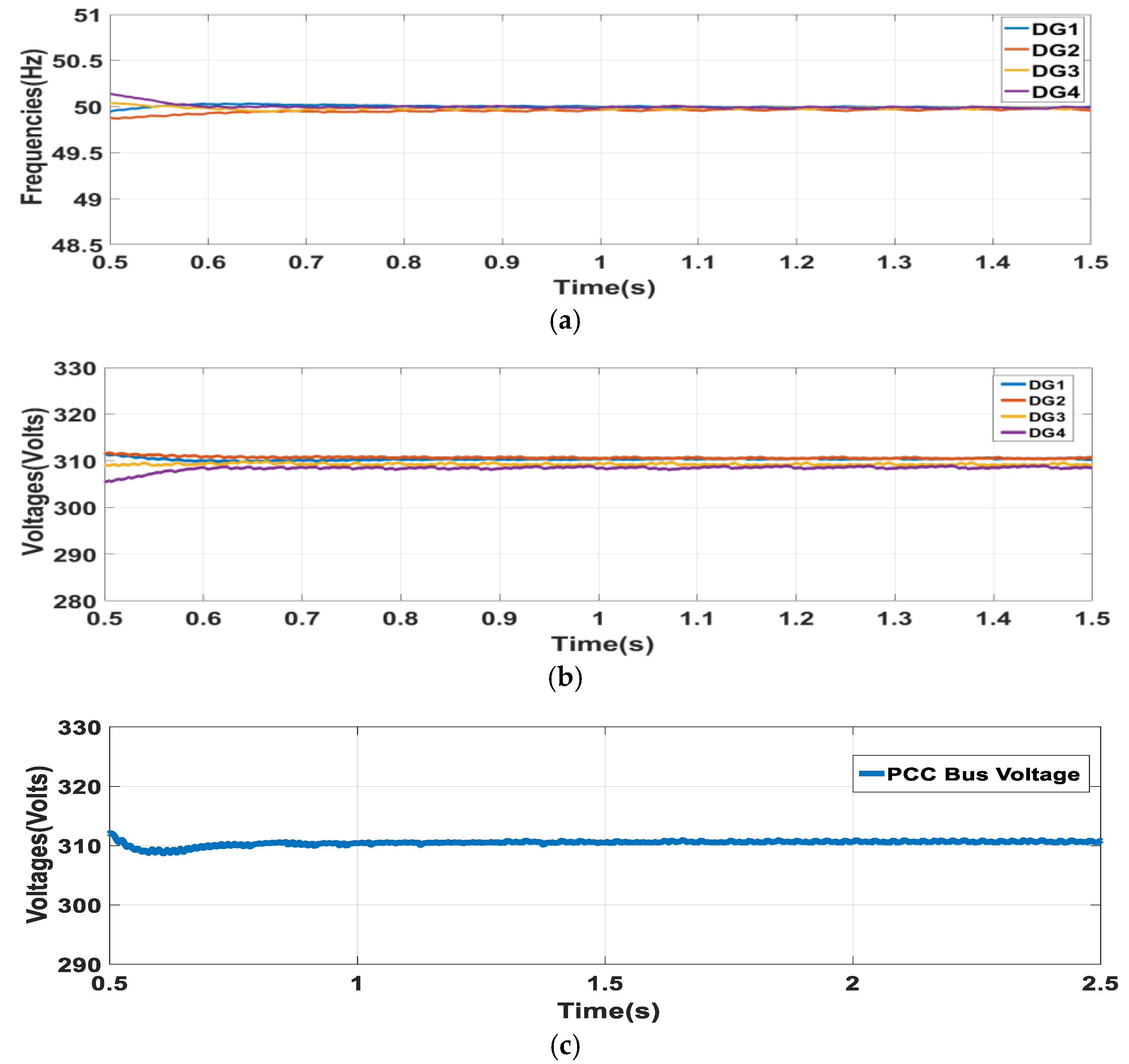
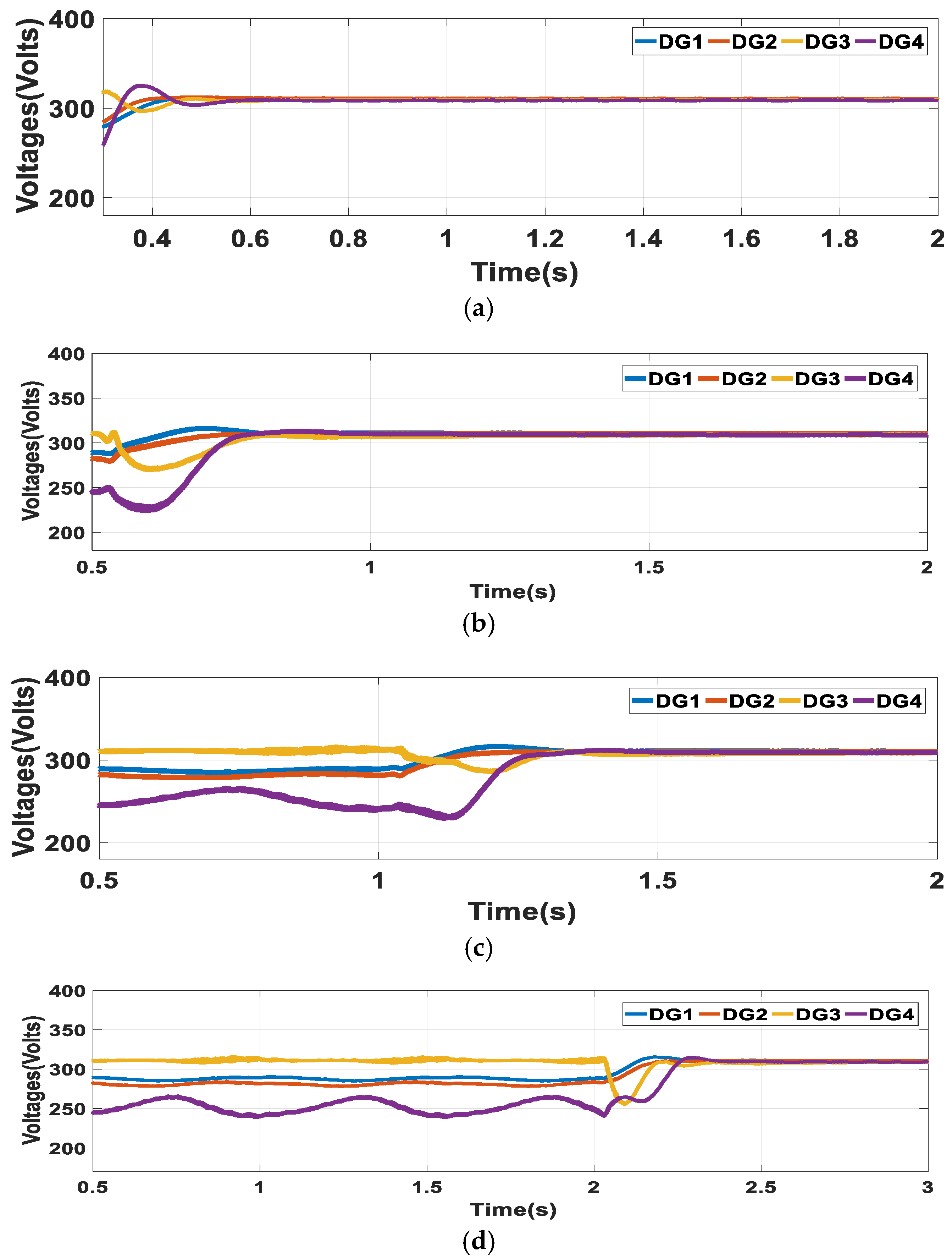
Section 5 discusses the time-domain simulation results. Conclusions along with future works are presented in Section 6.

2. The Proposed Distributed Secondary Controller

An autonomous MG consists of DG units, the power network, and local loads as depicted in Figure 1. In the test MG model, there are several nodes where some are associated with DG units and loads, and some are associated with only loads. The grid-forming voltage source inverters (VSIs) are essential in the islanded operation mode to form voltage and frequency within the MG. The control system of a droop controlled VSI, including inner voltage and current loops, is illustrated in Figure 1.

2.1. Traditional Droop Controller

The following equations represent the traditional droop controller of the ith DG for frequency control and voltage control to accomplish active and reactive power sharing, correspondingly:
f r e f i = f n k f i P i
{ v d r e f i = v n k v i Q i R v i r i i o d i + ω n L v i r i i o q i v q r e f i = R v i r i i o q i ω n L v i r i i o d i
where P i and Q i are the active and reactive powers of the ith DG units respectively, k f i and k v i are the frequency and voltage droop gains respectively, f n and v n are the nominal frequency and voltage respectively, v d r e f i and v q r e f i are the reference values for the direct-quadratic (dq) components of voltage magnitude in the synchronous reference frame, ω n denotes the nominal angular frequency, R v i r and L v i r are embedded to model the virtual resistance and virtual inductance, respectively, v o d i   and   v o q i are the dq components of the inverters output voltage and i o d i   and i o q i are the dq components of the inverters output current. Based on Equations (1) and (2), the frequency and voltage excursions would be established in the autonomous MG due to load variations.

2.2. Consensus-Based Distributed Secondary Control

The basics of the consensus algorithm and graph theory are described in [13] and thus not included here. In this research, a DSC system was applied locally by selecting the suitable control inputs g i and h i to adjust the frequency f r e f i and voltage magnitude v r e f i so that the frequency and voltage magnitude at MG nodes converge to the reference values f n and v n , respectively, while active and reactive power sharing are established. In the proposed DSC, as explained later, g i is related to frequency restoration and active power-sharing, h i and τ i are correlated to voltage restoration and reactive power-sharing respectively. Therefore, the proposed DSC signals, which give the reference values for the ith DG (synchronously including all the agents acting as a cluster) can be derived by the following equations.
Frequency restoration and active power-sharing: DSFC is used to re-establish the frequency and active power-sharing like this:
  f r e f i = f n k f i P i + g i
g i = D f i [ j N i a i j ( f r e f i f r e f j ) + b i ( f r e f i f n ) ] D P i [ j N i a i j ( k f i P i k f j P j ) ]
here D f i and D P i are all positive control gains and b i is the communication link indicator explained later. N i represents neighbouring nodes of node i and an adjacency matrix is defined as A G = [ a i j 0 ] R N × N where a i j = 1 if the ith node is coupled to the jth node and a i j = 0 otherwise [14].
Voltage restoration and reactive power-sharing: DSVC, which includes both the voltage controller and reactive power sharing controller, is chosen for the voltage regulation and reactive power sharing respectively, and can be designated by the following equations:
v r e f i = v n k v i Q i + ω n L v i r i   + h i + τ i
h i = D v i [ j N i a i j ( v d i f f i v d i f f j ) + b i ( v d i f f i v d i f f p c c ) ]
τ i = D Q i [ j N i a i j ( Q i Q i m a x Q j Q j m a x ) ]
where D v i and D Q i are all positive control gains and Q i m a x is the maximum reactive power of ith DG unit. v d i f f i and v d i f f p c c are designed through a PI controller such that both can restore to their reference values ( v n ) , where v d i f f p c c is calculated at the point of common coupling (PCC). v d i f f i and v d i f f p c c can be expressed by the following equations:
v d i f f i = K P ( v r e f v o i ) + K I ( v r e f v o i ) d t  
  v d i f f p c c = K P ( v r e f v p c c ) + K I ( v r e f v p c c ) d t
here, K P and K I are the proportional and integral control coefficients for the secondary controller. v o i = ( v o d i ) 2 + ( v o q i ) 2 is the output voltage of ith inverter as shown in Figure 1. v p c c = ( v p c c D ) 2 + ( v p c c Q ) 2 is the voltage at PCC. The subscripts d and q (D and Q) indicate the direct and quadrant component in the local (common) reference frame. In Equations (4) and (6), b i = 1 indicates the direct communication of the ith DG with the controller at PCC and otherwise b i = 0 .

3. Small-Signal Modelling

The small-signal state-space model for networked MG is obtained considering the small-signal modelling of VSIs, the power network and load dynamics. A systematic approach to obtaining the state-space equations of the network and loads is presented and combined with the inverters’ state-space equations. The reference frame of a given DG unit, preferably the biggest one (which has the smallest droop gain and thus less frequency variation to follow the slack bus concept in bulk power systems), is taken as a common reference frame. All other inverters were converted to this common reference frame utilizing the corresponding transformation, which is described in the following part. Here, the axis set ( D Q ) is the common reference frame rotating at a frequency ω c o m , whereas the axes ( d q ) i and ( d q ) j are the reference frame of the ith and jth inverters rotating at ω r e f i and ω r e f j , respectively. The transformation from the local reference frame to the common one is given as
[ f r e f i D Q ] = [ T i ] [ f r e f i d q ]
[ T i ] = [ c o s ( δ i ) s i n ( δ i ) s i n ( δ i ) c o s ( δ i ) ]
where δ i represents the phase angle difference of the ith inverter reference frame from the common reference frame. The details of the internal modelling of all these modules can be retrieved in [14] taking primary control into account. In this paper, the three-phase voltage and current are vector quantities presented in D Q frame while the other variables like frequency and power are scalar quantities.

3.1. Individual Inverter Modelling

Now, to derive the state-space model, in Equation (8) we had by defining σ i = ( v r e f v o i ) d t
Δ σ i ˙ = Δ v o i
Δ v o i = n d i Δ v o d i + n q i Δ v o q i
where, n d i = v o d i ( v o d i ) 2 + ( v o q i ) 2 ,   n q i = v o q i ( v o d i ) 2 + ( v o q i ) 2 .
Considering virtual impedances, the linearized inverter output voltage equations become
{ Δ v 0 d i = k v i Δ Q i + Δ h i + Δ τ i R v i r i Δ i 0 d i + X v i r i Δ i 0 q i Δ v 0 q i = R v i r i Δ i 0 q i X v i r i Δ i 0 d i
In reference to our proposed control strategy, the modelling of an individual inverter unit after linearization in the common reference frame considering only the primary control (droop control) can be written as follows:
[ Δ X ¯ i n v i ˙ ] = [ A ¯ i n v i ]   [ Δ X ¯ i n v i ] + [ B ¯ i n v i ]   [ Δ i 0 D Q i ] + [ C ¯ i n v i ]   [ Δ ω c o m ]
where Δ X ¯ i n v i = [ Δ δ i , Δ P i , Δ Q i ] T , and Δ i 0 D Q i = [ Δ i 0 D i ,   Δ i 0 Q i ] T represents the deviation of inverter output current in the DQ frame.
Consequently, the state-space model of an individual DG with DSC is obtained after linearization (around an operating point) and a combination of Equations (1)–(15) as follows:
{ [ Δ X i n v i ˙ ] = [ A 1 i n v i ] [ Δ X i n v i ] + [ A 2 i n v i ] [ Δ i 0 D Q i ] + [ A 3 i n v i ] [ Δ ω c o m ] + [ j ϵ N i A 4 i n v i j ] [ Δ X i n v j ] + [ A 5 i n v i ] [ Δ v d i f f p c c ] [ Δ ω r e f i Δ v 0 D Q i ] =   [ C i n v ω i M i n v i ] [ Δ X i n v i ] + [ 0 N i n v i ] [ Δ i 0 D Q i ]
where Δ X i n v i = [ Δ δ i , Δ P i , Δ Q i , Δ g i , Δ h i , Δ τ i , Δ σ i ] T .
In Equation (16), A 1 i n v i , A 2 i n v i , A 3 i n v i , A 4 i n v i j , A 5 i n v i , C i n v ω i , M i n v i and N i n v i are all the parameter matrices of the ith DG and given in Appendix A. A 4 i n v i j represents the correlations between D G i and the neighbor D G j provided by the DSC. Δ ω r e f i   and Δ ω c o m are the frequency deviations of the individual and common reference frame. Δ v 0 D Q i = [ Δ v 0 D i ,   Δ v 0 Q i ] T represents the deviations of inverter output voltage in the DQ frame.

3.2. Combined Model of All the Inverters

In this paper, four DGs were considered in the proposed MG model (Figure 2). Thus, by merging Equation (16) for four inverters, the combined model of all inverters in the linearized form can be written as:
{ [ Δ X i n v ˙ ] = [ A 1 i n v ] [ Δ X i n v ] + [ A 2 i n v ] [ Δ i 0 D Q ] + [ A 3 i n v ] [ Δ ω c o m ] + [ A 5 i n v ] [ Δ V d i f f p c c ] [ Δ v 0 D Q ] = [ M i n v ] [ Δ X i n v ] + [ N i n v ] [ Δ i 0 D Q ]
where
Δ X i n v = [ Δ X i n v 1   Δ X i n v 2   Δ X i n v 3   Δ X i n v 4 ] T , Δ i 0 D Q = [ Δ i 0 D Q 1 Δ i 0 D Q 2 Δ i 0 D Q 3 Δ i 0 D Q 4 ] T ,   [ Δ ω r e f i ] = [ Δ ω c o m ] Δ v 0 D Q = [ Δ v 0 D Q 1 Δ v 0 D Q 2 Δ v 0 D Q 3 Δ v 0 D Q 4 ] T , A 1 i n v = [ A 1 i n v 1 A 4 i n v 1 + A 3 i n v 2 · C i n v ω 2 0 A 4 i n v 2 A 4 i n v 3 A 4 i n v 2 + A 3 i n v 2 · C i n v ω 2 A 4 i n v 4 0 0 A 4 i n v 5 + A 3 i n v 2 · C i n v ω 2 A 1 i n v 3 A 4 i n v 6 A 4 i n v 7 A 3 i n v 2 · C i n v ω 2 A 4 i n v 8 A 1 i n v 4 ] , A 2 i n v = d i a g ( A 2 i n v 1 , A 2 i n v 2 , A 3 i n v 3 , A 4 i n v 4 ) , A 3 i n v =   [ 0   0   A 3 i n v 2   0 ] , A 5 i n v =   [ 0   0   A 5 i n v 2   0 ] , C i n v ω = [ 0 C i n v ω i 0 0 ] , M i n v   =   d i a g ( M i n v 1 , M i n v 2 , M i n v 3 , M i n v 4 ) , N i n v = d i a g ( N i n v 1 , N i n v 2 , N i n v 3 , N i n v 4 )
In this modelling technique, all the individual DG inverters are modelled separately and then combined, which will be finally integrated with the network and load models.

3.3. Network and Load Model

The network and load models were obtained by linearizing the node voltage equations considering Figure 2. There were no incoming currents in the network or load nodes. From the linearized node voltage equations, we got the following:
Y 1 Δ v 0 D Q + Y 2 Δ v n e t l o a d D Q = Δ i 0 D Q
Y 3 Δ v 0 D Q + Y 4 Δ v n e t l o a d D Q = 0
where Δ i 0 D Q   represents Δ i 0 D Q i of all the DG units, Δ v 0 D Q represents Δ v o D Q i of all the inverters and the voltage deviations of all the network and load nodes are represented by Δ v n e t l o a d D Q . Y 1 ,   Y 2 ,   Y 3 and Y 4 are the submatrices of the nodal admittance matrix Y, i.e., Y = [ Y 1 Y 2 Y 3 Y 4 ] . By eliminating Δ v n e t l o a d D Q , we had
Δ v 0 D Q = ( Y 1 Y 2 Y 4 1 Y 3 ) 1 Δ i 0 D Q
Substituting Equation (19) into Equation (17), we can write
Δ i 0 D Q = ( ( Y 1 Y 2 Y 4 1 Y 3 ) 1 N i n v ) 1     M i n v   Δ X i n v
Δ v d i f f is defined in terms of Δ i 0 D Q as follows:
Δ v d i f f D Q = I M P p c c Δ i 0 D Q
where I M P p c c is the impedance matrix and can be calculated from the nodal admittance matrix Y of node voltage equations.

3.4. Complete Small-Signal Model

Similarly to define v p c c considering Equation (9) and letting = ( v r e f v p c c ) d t , we had
Δ ˙ = Δ v p c c
Δ v d i f f p c c = K P Δ v p c c + K I Δ
here, Δ v p c c = m D Δ v p c c D + m Q Δ v p c c Q where, m D = v p c c D ( v p c c D ) 2 + ( v p c c Q ) 2 ,   m Q = v p c c Q ( v p c c D ) 2 + ( v p c c Q ) 2 .
The complete MG dynamic model in the linearized form can be formulated by combining Equations (17)–(22) as follows.
[ Δ X i n v ˙ Δ ˙ ] = A s y s t e m [ X i n v Δ ]
The detailed stability analysis includes the mechanism of the unwanted dynamic behaviour, along with the oscillations can be accomplished utilizing the eigen-arrangement of the system’s state matrix, A s y s t e m   as given in the next section.

4. Stability Analysis

Single line drawing of the experimental MG model including four inverter-based DG units, local loads and feeder lines is shown in Figure 2. The MG considered here was a 311 V and 50 Hz system and was simulated in MATLAB. The MG functioned in the autonomous mode. Here, every load was considered as a 3-phase series RL load and every feeder line was a 3-phase series RL branch. Figure 2 also shows the sparse communication link (blue dashed lines) of the MG system, and its related adjacency matrix was A G = [aij], where the DG2 outputs were considered as the nominal values and the pinning gain b2 in Equations (3) and (5) was set as b2 = 1.

4.1. Eigenvalue Analysis

System dynamic behaviour and the outcomes from the stability analysis for the test MG under the suggested DSC were discussed in this section. In line with the stated linearized model in the prior section, the subsequent eigenvalues including DSC were presented in Figure 3 for stable operation. As the eigenvalues of high and intermediate frequency modes had insignificant influences on system stability [14], this paper mainly put an emphasis on the analysis of the low-frequency modes. There were nine less damped modes, among which four were introduced by the proposed DSC, i.e., modes 6–9. It was assumed that the communications among the DG units are followed by the directed graph as in Figure 2 (blue dashed line).
Participation Factor: The participation factor was employed to find the relationship between the state variables and the modes and is the multiplication of corresponding quantity in the right and left eigenvectors of the state matrix [14]. For the primary droop control, the low-frequency modes are primarily affected by the states of the active power droop controller (1), i.e., Δδi and ΔPi recommended by participation factors in [4]. Figure 4 shows the relation of the participation factors of the system state variables associated with the modes 6–9 considering the proposed DSC in action. Participation factors related to modes 1–5 were mainly for the primary droop control, and this was the same as the case when only primary droop control was functional to the system, which was not the main concern in this paper. Thus, only the effects of proposed DSC in the modal analysis were discussed and those of modes 1–5 are not shown. A brief description of the outcomes (Figure 4) is given as follows.
Figure 4a indicates that Δ δ i , Δ P i and Δ g i of every DG unit actively participated in the oscillation caused by mode 6, revealing the direct participation of these states of all the DG units in the stability. As Δ g i is the state variable for the DSC as in Equation (3) it is remarkably affected by the secondary controller gains D f i   and D P i and thus affects the stability of the system.
Figure 4b illustrates that the states Δ Q i , Δ h i and Δ τ i of the proposed DSC for voltage control and reactive power-sharing considerably contributed to creating modes 7 and 8 and were strongly affected by the controller gain D Q i . DSC gain D v i had less of an effect on stability.
Figure 4c revealed that mode 9 was caused by the states Δ Q i and Δ . The states Δ and Δ Q i   were strongly associated with DSC proportional control gain ( K P ), integral control gain ( K I ) and virtual reactance ( X v i r i ), respectively.
The detailed effects of the controller parameters K P , K I , D f i ,     D v i ,     D P i , D Q i   and virtual impedance values Z v i r i on the less damped modes were analysed in detail in the following section.

4.2. Relationship between System Stability and DSC Parameters

Sensitivity of the system stability to the distributed control parameters was analysed with the help of stability margin. The traces of low-frequency modes of the system as functions of K I , K P ,   D f i , D P i , D Q i and Z v i r i (which includes R v i r i and X v i r i ) were taken into account to determine the effect on stability. Figure 5 presents the traces of less damped modes as the function of X v i r i , K I , K P , D Q i , D f i and D P i . The traces of low-frequency modes as functions of R v i r i were similar to X v i r i , and those of K P were similar to K I , which are not shown here. Note that the variation of D v i had comparatively less effect on system stability, and thus it is not shown here. Figure 5a shows the changes in the damping of mode 9 when K I varied from 5 to 40. These variations mainly affected the least damped mode 9.
Figure 5b shows variation in the damping of the modes 7 and 8 when X v i r i varied from 0.01 to 0.1 Ω, and D Q i varied from 10 to 40, respectively. From this, it is clear that increasing the value of X v i r i and D Q i had the opposite effects on system stability. Figure 5c shows that D f i and D P i   also had reverse effects on the oscillation. Table 1 gives a summary of the above analysis. On the other hand, finding suitable values for DSC parameters was difficult by traditional approaches, e.g., trial and error scheme and from the traces of low-frequency modes for stability improvement. Accordingly, intelligent fuzzy logic was used for proper tuning of controller parameters for stability improvement in terms of fast response, appropriate damping and satisfactory stability margin.

4.3. Tuning the DSC Parameters Based on Fuzzy-Logic

This paper presents a fuzzy logic-based tuner for regulating the DSC parameters and virtual impedance used in the consensus-based DSC framework. Membership function, fuzzy logic operators and if-then rules are the usual elements of a fuzzy inference system. These elements were used to calculate the mapping from the input values to the output values, and it involved three subprocesses: fuzzification, aggregation and defuzzification. Here, the Mamdani fuzzy inference scheme was applied. The goal was to determine the DSC parameters K I , K P ,     D f i , D P i ,     D Q i and virtual impedance values R v i r i and X v i r i related to the fuzzy logic system as in Figure 6. A set of fuzzy rules containing 16 rules was taken for tuning the controller parameters. The triangular membership function (MF) was employed for arranging the fuzzy rules, which is the most popular one. The input rules were collected by using the AND operator. The training arrangement is presented as follows.
Fuzzifier: The inputs, outputs and their ranges were identified in this step. The membership functions for inputs and outputs were organized as: not stable (NOTS), very low stability (VLS), low stability (LS) and normal stability (NS). Figure 7 displays the MFs for input and output constraints of every input and output. In this paper, frequency stability margin and voltage stability margin were considered as inputs, while DSC parameters and virtual impedance were considered as outputs.
Aggregation: The knowledge base for the fuzzy logic system is a group of fuzzy if-then rules as expressed in the following formula, e.g., rule 10 from Table 2 describes the following:
  • R 10 : I f   f r e f   i s   ¥ f r e f ( L S )   a n d   v r e f   i s   ¥ v r e f ( V L S ) ,   t h e n   D p i   i s   ¥ D p i ( L S )   ,
  • D v i   i s   ¥ D v i ( L S ) , D Q i   i s   ¥ D Q i ( L S ) ,     R v i r i   i s   ¥ R v i r i ( L S ) ,     a n d   X v i r i   i s   ¥ X v i r ( L S ) .
According to this rule, if the degree of MFs (¥) for frequency stability region is LS and for voltage stability region is VLS, the outcomes for all outputs are LS. The rules are summarized in Table A1 (Appendix A).
Defuzzifier: The fuzzy outputs were transformed to non-fuzzy values in this step. Thus, the centre average defuzzification principle based on triangular was applied to measure the crisp outputs, i.e., DSC parameters.
Based on the above rules, the estimated values for DSC parameters and virtual impedance were determined and given in Table 3. In this study, we assumed that the DSC is activated from the beginning with the droop control (primary control). The importance of parameters X v i r i and D Q i was designated in accordance with voltage and reactive power. The value of X v i r i was less than 0.22 Ω, which indicates that, for values bigger than 0.22 Ω, the system might be unstable. Similarly, the suitable values of K I ,     K P , D f i ,     D P i ,     D Q i and R v i r i were found to utilize the fuzzy logic tuner. These values were also verified by the time-domain simulation results. The following sections give detailed explanations with the simulation results. Figure 8 shows the 3-dimensional representations of outputs Dfi and X v i r i with inputs. The eigenvalue spectrum of dominant modes is presented in Figure 9, which confirms the usefulness of the fuzzy logic tuner for system stability improvement.

5. Time-Domain Simulation Results

An MG test model as in Figure 2 was considered to validate the effectiveness of the offered DSC scheme. Matlab/Simscape software was used for simulation of the test MG model. The MG, load and line parameters used in the simulations are given in Table A2, Table A3 and Table A4 (Appendix A). All the DSC gains were considered to be the same for all the DGs.

5.1. Case Studies

First, the simulation results could be categorized into the following two groups:
  • Group 1: Results with proposed DSC with initial parameters (without tuning).
  • Group 2: Results with proposed DSC with the tuned parameters by the fuzzy logic tuner.
In group 1, the proposed DSC performs with not-tuned parameter values as shown in Figure 10. The simulation results of the frequency and voltage restoration are shown in Figure 10. From the results, it can be seen that the initial DSC parameters produced transient oscillations, which was also verified by the eigenvalue analysis. For group 1, convergence time for frequencies were 1.1 s and for voltages were 1.2–1.5 s. As we want to verify several case studies (case 1–case 7) to show the robustness of our proposed DSC, we considered the tuned parameters for those case studies due to space limit. However, to get better performance, the fuzzy-logic tuner was used for tuning the DSC parameters and virtual impedance values. The simulations from group 2 ere conducted with the following six case studies.
  • Case 1: Voltage and Frequency Restoration
The simulation outcomes of case 1 are given in Figure 11.
When our proposed DSC was employed, the restoration process of both voltage and frequency to their reference values respectively ( v r e f = 311   V , f r e f = 50   Hz ) was very fast with less oscillation as compared with Figure 10. Thus, the fuzzy tuner could improve (convergence time improved for frequencies from 1.1 to 0.6 s and for voltages from 1.2–1.5 s to 0.7–0.8 s) the performance of DSC.
  • Case 2: Load Changing after Reaching the Steady State
In this case, several scenarios were analysed in the simulations according to the power flow and loading condition at each DG after reaching the steady-state (Figure 12) as follows.
According to our proposed DSC, power sharing was in proportion to the capacities of DGs (ratio of capacities is DG1:DG2:DG3:DG4 = 2:2:1:1) as shown in Figure 12. At t = 3 s, Load #3 was disconnected from DG3, and at t = 5 s, Load #3 was again connected to DG3. At t = 6 s, Load #2 was increased by including an additional load equivalent to Load #5 and at t = 8 s, the additional load was removed from Load #2.
The simulation results from Figure 12 for load change show that the proposed DSC could accurately share active and reactive powers according to their capacities under the load disturbances.
  • Case 3: Occurrence of Communication Delay
In this case study, communication delay on the proposed DSC scheme was conducted with four scenarios, i.e., fixed communication delay of 0.1 s, 0.5 s, 1 s and 2 s in the MG. The proposed DSC was commenced from the beginning. For easiness, simply the voltage responses for the DG units were given for the four scenarios as shown in Figure 13. It can be realized from Figure 13a,b that the controller performed properly with small time delays of 0.1 s and 0.5 s. Figure 13c,d shows that, with the increase of the time delay to 1–2 s, the voltage was restored with minor deviations, but with increased convergence times. Thus, it could be concluded that the proposed DSC can still help the system with restoration under the communication latency.
  • Case 4: Loss of the Communication Link
Communication link failure is a common phenomenon in real-world applications. The MG system still needs to be stable in such conditions. In this case study, the simulation is done with the following scenarios.
  • Stage 1: There is no loss of communication link when t ≤ 2.6 s, and the MG system rapidly reaches the steady state.
  • Stage 2: The MG system experiences a loss of communication link from DG4 to DG1 when t > 2.6 s.
The simulation results are given in Figure 14, showing that the proposed DSC technique could deal well with the conditions of communication link failure, though there was transient oscillation that occurred for the loss of the communication link.
  • Case 5: Effects on Different Communication Topologies
The effects of diverse communication topologies (line, ring and mesh) as shown in Figure 15 on the proposed model were analysed in this case. Convergence time with different topologies is summarized in Table 3. Table 3 reveals that the system dynamic behaviour changed with different communication topologies. A low amount of communication links (line) increased the convergence time, while a high number of communication links (mesh) raised the complexity of the communication network and also the system implementation cost.
  • Case 6: Plug-and-Play Capability
Once synchronizing and reaching steady-state condition by the DSC, the plug-and-play capability of the controllers was assessed in this case study by disconnecting DG3 at t = 10 s and connecting it at t = 14 s. The following observations were made from the simulation results, (i) disconnection of a DG unit indicates the failure of all the communication links associated with that DG unit, (ii) the lost communication links are retrieved after reconnecting the DG unit and (iii) a synchronization procedure was required to coordinate DG3 with the remaining MG before reconnection. Figure 16 shows the performance of DSC with plug-and-play operation. According to Figure 16, it could be concluded that reconnection (at t = 14 s) of DG produced more oscillation than the disconnection/sudden loss (t = 10 s) of any DG unit.
  • Case 7: MG with Fault Conditions
To study the dynamic performance of the MG model with the proposed DSC, performances of voltage and frequency and power-sharing are observed under the maximum fault condition. After reaching the steady-state condition, a three-phase to ground fault occurred at bus 1 at t = 3 s and the fault was cleared at t = 4 s. Figure 17 shows the controller performance under that fault condition, and it can be understood that the voltage and frequency controllers had the ability of preserving the system stability afterwards the fault clearance. Moreover, accurate power-sharing was achieved within a very short time after the fault clearance. It can be said that the proposed DSC was robust in maintaining the system stability under the sudden fault condition.

5.2. Convergence Time

As stated in the literature review, inadequate studies were stated that consider both the voltage and frequency restoration problems in a distributed way. In comparison with the most relevant works, as in [59], Table 3 reveals that the proposed control approach required less time to drive the frequencies to the steady-state values, which were 0.56 s, compared to 1.9 s in [59]. Additionally, the proposed control strategy performed well even though changes occurred in load, communication topology and loss of DG and even in fault conditions, which means by the proposed DSC the dynamics of the underlying system could quickly converge to the reference values under different disturbing conditions.

6. Conclusions

A noble cooperative DSC for islanded AC MG has been established taking the lossy-line network into account, which similarly preserves the precise active and reactive power-sharing while keeping PCC bus voltage at its reference value at the same time. State-space modelling and small-signal stability analysis for the networked MG have shown that new less-damped modes are the consequences of the DSC. Intelligent fuzzy-based parameter-tuner is applied to improve system stability. One of the main advantages of using a fuzzy-logic tuner is its low computational complexity in comparison to other existing methods. Theoretical analysis and time-domain simulation case scenarios of a test MG system have been explained to show the robust performance of the suggested DSC scheme. Under the proposed control method, the networked MG model can reach a steady state after different disturbances (even after fault condition) without significant transients in the system frequency, voltage and active and reactive power-sharing. The proposed DSC shows a fast response to achieve consensus and indicates better robust characteristics in terms of controller establishment, structure design and the variation of loads compared with most related existing work on DSC, which is also discussed in the simulation section.
However, as communication is the major part of the secondary control level, cyber security is of primary importance to the assurance safe task of cyber-physical systems, which has obtained growing attention in the control community. To prevent our presented scheme in Figure 2 from malicious activities like “Replay Attack” or “False Data Injection” [60,61], we will consider it as a future work of this paper.

Author Contributions

Data curation, M.B.; formal analysis, M.B. and M.E.; investigation, M.B.; methodology, M.B. and M.E.; software, M.B. and M.A.; supervision, M.B., L.L. and J.Z.; validation, M.B. and M.E.; visualization, M.B.; writing—original draft, M.B.; Writing—review and editing, L.L. and M.E. All authors have read and agreed to the published version of the manuscript.

Funding

This research received no external funding.

Data Availability Statement

No new data were created or analyzed in this study. Data sharing is not applicable to this article.

Conflicts of Interest

The authors declare no conflict of interest.

Appendix A

Table A1. Fuzzy rule set for inputs and outputs.
RuleFuzzy Parameters
f r e f v r e f D f i D P i D Q i X v i r i
1NOTSNOTSNOTSNOTSNOTSNOTS
2NOTSVLSNOTSVLSVLSVLS
3NOTSLSNOTSLSLSLS
4NOTSNSLSLSLSLS
5VLSNOTSNOTSVLSVLSVLS
6VLSVLSNOTSVLSVLSVLS
7VLSLSLSLSLSLS
8VLSNSLSLSLSLS
9LSNOTSNOTSVLSVLSVLS
10LSVLSLSLSLSLS
11LSLSLSLSLSLS
12LSNSLSLSLSLS
13NSNOTSNOTSVLSVLSVLS
14NSVLSVLSLSVLSVLS
15NSLSNSNSLSNS
16NSNSNSNSNSNS
Table A2. Specifications for test system.
Names of ParametersSymbolValueUnit
Microgrid Test Model Parameters
DC Voltage Value V d c 700V
Nominal Voltage v r e f 311V
Nominal Frequency f r e f 50Hz
Filter Inductor Resistance R f 0.1Ω
Filter Inductor Inductance L f 1.35mH
Filter Inductor Capacitance C f 50µF
Coupling Inductor Resistance R c 0.03Ω
Coupling Inductor Inductance L C 0.1mH
Voltage Controller Specifications
Proportional Gain K p v 0.05-
Integral Gain K i v 390-
Feed Forward GainF0.75-
Current Controller Specifications
Proportional Gain K p c 10.2-
Integral Gain K i c 16 × 103-
Power Controller Specifications
Frequency Droop Gain k f i ( i = 1 ,   2 ) 3.33 × 10⁻⁵-
k f i ( i = 3 ,   4 ) 6.67 × 10⁻⁵-
Voltage Droop Gain k v i ( i = 1 ,   2 ) 2.5 × 10⁻⁴-
k v i ( i = 3 ,   4 ) 5 × 10⁻⁴-
Table A3. Line data used in the test system.
Line Data
No.R (Ω)L (µH)No.R (Ω)L (µH)
Line 1,20.23312Line 5,60.12312
Line 3,40.30318Line 7,80.21316
Table A4. Load data used in the test system.
Line Data
No.R (Ω)L (mH)No.R (Ω)L (mH)
Load 1,23050Load 5,62012
Load 3,44020Load 7,81850
A 1 i n v i = [ 0 k f i 0 0 0 0 0 V b D sin ( δ 0 ) + V b Q cos ( δ 0 ) ω c ω c I o d k v i 0 ω c I o d ω c I o d 0 V b D cos ( δ 0 ) V b Q sin ( δ 0 ) 0 ω c + ω c I o d k v i 0 ω c I o q ω c I o q 0 0 2 k f i ( D f i D p i ) 0 2 D f i 0 0 0 0 0 2 D v i K P n d i k v i 0 2 D v i K P n d i 2 D v i K P n d i 2 D v i K I 0 0 2 D Q i Q i m a x 0 0 0 0 0 0 n d i k v i 0 n d i n d i 0 ]
A 2 i n v i = [ 0 0 ω c I o d R v i r i + ω c I o d X v i r i ω c V o d ω c I o d R v i r i + ω c I o d X v i r i ω c V o d ω c I o q R v i r i ω c I o d X v i r i + ω c V o q ω c I o d R v i r i + ω c I o d X v i r i ω c V o d 0 0 2 D v i K p ( n d i R v i r i + n q i X v i r i ) 2 D v i K p ( n q i R v i r i n d i X v i r i ) 0 0 n d i R v i r i + n q i X v i r i n q i R v i r i n d i X v i r i ] · [ cos ( δ 0 ) sin ( δ 0 ) sin ( δ 0 ) cos ( δ 0 ) ] ,   A 3 i n v i = [ 1 0 0 0 0 0 0 ]
A 4 i n v i j = [ 0 0 0 0 0 0 0 0 0 0 0 0 0 0 0 0 0 0 0 0 0 0 j N i k f j ( D P j D f j ) 0 j N i D f j 0 0 0 0 0 j N i D v j K P n d j k v j 0 j N i D v j K P n d j j N i D v j K P n d j j N i D v j K I 0 0 j N i D Q j Q j m a x 0 0 0 0 0 0 0 0 0 0 0 ] ,   A 5 i n v i = [ 0 0 0 0 D v i b i 0 0 ]
M i n v i = [ 0 0 k v i 0 1 1 0 0 0 0 0 0 0 0 ] ,   N i n v i = [ R v i r i X v i r X v i r R v i r i ] ,   C i n v w i = [ 0 k f i b i 0 0 0 0 0 ]
A s y s = [ A 1 A 2 A 3 A 4 ] ,   where   A 1 = A 1 i n v + A 2 i n v ( ( Y 1 Y 2 Y 4 1 Y 3 ) 1 N i n v ) 1       M i n v + A 3 i n v   C i n v ω + A 5 i n v A p c c K P i I M P p c c ( ( Y 1 Y 2 Y 4 1 Y 3 ) 1 N i n v ) 1       M i n v
A 2 = A 5 i n v K I ,     A 3 = A p c c I M P p c c ( ( Y 1 Y 2 Y 4 1 Y 3 ) 1 N i n v ) 1       M i n v ,   A 4 = 0 ,   where   A p c c = [ 0   M p c c   0   0 ]

References

  1. Hossain, M.A.; Pota, H.R.; Hossain, M.J.; Blaabjerg, F. Evolution of microgrids with converter-interfaced generations: Challenges and opportunities. Int. J. Electr. Power Energy Syst. 2019, 109, 160–186. [Google Scholar] [CrossRef]
  2. Bidram, A.; Davoudi, A. Hierarchical Structure of Microgrids Control System. IEEE Trans. Smart Grid 2012, 3, 1963–1976. [Google Scholar] [CrossRef]
  3. Espina, E.; Llanos, J.; Burgos-Mellado, C.; Cardenas, R.; Martinez-Gomez, M.; Sáez, D. Distributed Control Strategies for Microgrids: An Overview. IEEE Access 2020, 8, 1. [Google Scholar] [CrossRef]
  4. Eskandari, M.; Li, L.; Moradi, M. Improving power sharing in islanded networked microgrids using fuzzy-based consensus control. Sustain. Energy Grids Netw. 2018, 16, 259–269. [Google Scholar] [CrossRef]
  5. Guerrero, J.M.; Vasquez, J.C.; Matas, J.; De Vicuna, L.G.; Castilla, M. Hierarchical Control of Droop-Controlled AC and DC Microgrids—A General Approach Toward Standardization. IEEE Trans. Ind. Electron. 2011, 58, 158–172. [Google Scholar] [CrossRef]
  6. Begum, M.; Abuhilaleh, M.; Li, L.; Zhu, J. Distributed secondary voltage regulation for autonomous microgrid. In Proceedings of the 2017 20th International Conference on Electrical Machines and Systems (ICEMS), Dhaka, Bangladesh, 21–23 December 2017; pp. 1–6. [Google Scholar]
  7. Llanos, J.; Olivares, D.E.; Simpson-Porco, J.W.; Kazerani, M.; Sáez, D. A Novel Distributed Control Strategy for Optimal Dispatch of Isolated Microgrids Considering Congestion. IEEE Trans. Smart Grid 2019, 10, 6595–6606. [Google Scholar] [CrossRef]
  8. Wu, X.; Shen, C.; Iravani, R. A Distributed, Cooperative Frequency and Voltage Control for Microgrids. IEEE Trans. Smart Grid 2016, 9, 2764–2776. [Google Scholar] [CrossRef]
  9. Begum, M.; Li, L.; Zhu, J. Distributed control techniques for autonomous AC Microgrid-A brief review. In Proceedings of the 2017 IEEE Region 10 Humanitarian Technology Conference (R10-HTC), Dhaka, Bangladesh, 21–23 December 2017; pp. 357–362. [Google Scholar]
  10. Wu, X.; Shen, C. Distributed Optimal Control for Stability Enhancement of Microgrids With Multiple Distributed Generators. IEEE Trans. Power Syst. 2017, 32, 4045–4059. [Google Scholar] [CrossRef]
  11. Machado, S.d.J.M.; Olivieira da Silva, S.A.; Boffino de Almeida Monteiro, J.R.; Albano de Oliveira, A. Network Modeling Influence on Small-Signal. Reduced-Order Models of Inverter-Based AC Microgrids Considering Virtual Impedance. IEEE Trans. Smart Grid 2021, 12, 79–92. [Google Scholar] [CrossRef]
  12. Rahman, A.; Syed, I.; Ullah, M. Small-Signal. Stability Criteria in AC Distribution Systems—A Review. Electronics 2019, 8, 216. [Google Scholar] [CrossRef] [Green Version]
  13. Begum, M.; Li, L.; Zhu, J.; Li, Z. State-Space Modeling and Stability Analysis for Microgrids with Distributed Secondary Control. In Proceedings of the 2018 IEEE 27th International Symposium on Industrial Electronics (ISIE), Cairns, Australia, 13–15 June 2018; pp. 1201–1206. [Google Scholar]
  14. Pogaku, N.; Prodanovic, M.; Green, T.C. Modeling, Analysis and Testing of Autonomous Operation of an Inverter-Based Microgrid. IEEE Trans. Power Electron. 2007, 22, 613–625. [Google Scholar] [CrossRef] [Green Version]
  15. Shafiee, Q.; Nasirian, V.; Vasquez, J.C.; Guerrero, J.; Davoudi, A. A Multi-Functional Fully Distributed Control Framework for AC Microgrids. IEEE Trans. Smart Grid 2018, 9, 3247–3258. [Google Scholar] [CrossRef] [Green Version]
  16. Ahumada, C.; Cardenas, R.; Saez, D.; Guerrero, J.M. Secondary Control. Strategies for Frequency Restoration in Islanded Microgrids With Consideration of Communication Delays. IEEE Trans. Smart Grid 2016, 7, 1430–1441. [Google Scholar] [CrossRef] [Green Version]
  17. Morstyn, T.; Hredzak, B.; Agelidis, V.G. Distributed Cooperative Control of Microgrid Storage. IEEE Trans. Power Syst. 2015, 30, 2780–2789. [Google Scholar] [CrossRef]
  18. Golsorkhi, M.S.; Lu, D.D.C. A Control Method for Inverter-Based Islanded Microgrids Based on V-I Droop Characteristics. IEEE Trans. Power Deliv. 2015, 30, 1196–1204. [Google Scholar] [CrossRef]
  19. Schiffer, J.; Seel, T.; Raisch, J.; Sezi, T. Voltage Stability and Reactive Power Sharing in Inverter-Based Microgrids With Consensus-Based Distributed Voltage Control. IEEE Trans. Control. Syst. Technol. 2016, 24, 96–109. [Google Scholar] [CrossRef] [Green Version]
  20. Simpson-Porco, J.W.; Dörfler, F.; Bullo, F. Synchronization and power sharing for droop-controlled inverters in islanded microgrids. Automatica 2013, 49, 2603–2611. [Google Scholar] [CrossRef] [Green Version]
  21. Simpson-Porco, J.W.; Shafiee, Q.; Dorfler, F.; Vasquez, J.C.; Guerrero, J.M.; Bullo, F. Secondary Frequency and Voltage Control of Islanded Microgrids via Distributed Averaging. IEEE Trans. Ind. Electron. 2015, 62, 7025–7038. [Google Scholar] [CrossRef]
  22. Deng, W.; Dai, N.; Lao, K.-W.; Guerrero, J.M. A Virtual-Impedance Droop Control for Accurate Active Power Control and Reactive Power Sharing Using Capacitive-Coupling Inverters. IEEE Trans. Ind. Appl. 2020, 56, 1. [Google Scholar] [CrossRef]
  23. Eskandari, M.; Li, L. Microgrid operation improvement by adaptive virtual impedance. IET Renew. Power Gener. 2019, 13, 296–307. [Google Scholar] [CrossRef]
  24. Hou, S.; Fan, Z.; Fang, L.; Chen, J. Accurate Reactive Power Sharing for Microgrid Using Distributed Adaptive Virtual Impedance. In Proceedings of the 2020 IEEE 29th International Symposium on Industrial Electronics (ISIE), Delft, The Netherlands, 17–19 June 2020; pp. 624–629. [Google Scholar]
  25. Razi, R.; Iman-Eini, H.; Hamzeh, M.; Bacha, S. A Novel Extended Impedance-Power Droop for Accurate Active and Reactive Power Sharing in a Multi-Bus Microgrid With Complex Impedances. IEEE Trans. Smart Grid 2020, 11, 3795–3804. [Google Scholar] [CrossRef]
  26. Wu, X.; Shen, C.; Iravani, R. Feasible Range and Optimal Value of the Virtual Impedance for Droop-Based Control of Microgrids. IEEE Trans. Smart Grid 2017, 8, 1242–1251. [Google Scholar] [CrossRef]
  27. Xu, H.; Yu, C.; Liu, C.; Wang, Q.; Liu, F.; Li, F. An Improved Virtual Capacitor Algorithm for Reactive Power Sharing in Multi-Paralleled Distributed Generators. IEEE Trans. Power Electron. 2019, 34, 10786–10795. [Google Scholar] [CrossRef]
  28. Alsafran, A.S.; Daniels, M.W. Adaptive Virtual Impedance Consensus Control for Reactive Power Sharing. In Proceedings of the 2020 IEEE Kansas Power and Energy Conference (KPEC), Manhattan, KS, USA, 13–14 July 2020; pp. 1–6. [Google Scholar]
  29. De Brabandere, K.; Bolsens, B.; Keybus, J.V.D.; Woyte, A.; Driesen, J.; Belmans, R.; Leuven, K. A voltage and frequency droop control method for parallel inverters. IEEE Trans. Power Electr. 2007, 22, 1107–1115. [Google Scholar] [CrossRef]
  30. Lee, C.-T.; Chu, C.-C.; Cheng, P.-T. A New Droop Control Method for the Autonomous Operation of Distributed Energy Resource Interface Converters. IEEE Trans. Power Electron. 2013, 28, 1980–1993. [Google Scholar] [CrossRef]
  31. Vovos, P.N.; Kiprakis, A.E.; Wallace, A.R.; Harrison, G.P. Centralized and Distributed Voltage Control: Impact on Distributed Generation Penetration. IEEE Trans. Power Syst. 2007, 22, 476–483. [Google Scholar] [CrossRef] [Green Version]
  32. Li, Q.; Chen, F.; Chen, M.; Guerrero, J.M.; Abbott, D. Agent-Based Decentralized Control Method for Islanded Microgrids. IEEE Trans. Smart Grid 2015, 7, 1. [Google Scholar] [CrossRef] [Green Version]
  33. Liu, W.; Gu, W.; Sheng, W.; Meng, X.; Wu, Z.; Chen, W. Decentralized Multi-Agent System-Based Cooperative Frequency Control for Autonomous Microgrids With Communication Constraints. IEEE Trans. Sustain. Energy 2014, 5, 446–456. [Google Scholar] [CrossRef]
  34. Vaccaro, A.; Velotto, G.; Zobaa, A.F. A Decentralized and Cooperative Architecture for Optimal Voltage Regulation in Smart Grids. IEEE Trans. Ind. Electron. 2011, 58, 4593–4602. [Google Scholar] [CrossRef]
  35. Lai, J.; Zhou, H.; Lu, X.; Yu, X.; Hu, W. Droop-Based Distributed Cooperative Control for Microgrids With Time-Varying Delays. IEEE Trans. Smart Grid 2016, 7, 1775–1789. [Google Scholar] [CrossRef]
  36. Nasirian, V.; Shafiee, Q.; Guerrero, J.M.; Lewis, F.L.; Davoudi, A. Droop-Free Distributed Control for AC Microgrids. IEEE Trans. Power Electron. 2016, 31, 1600–1617. [Google Scholar] [CrossRef] [Green Version]
  37. Turitsyn, K.; Sulc, P.; Backhaus, S.; Chertkov, M. Options for Control of Reactive Power by Distributed Photovoltaic Generators. Proc. IEEE 2011, 99, 1063–1073. [Google Scholar] [CrossRef] [Green Version]
  38. Teo, T.T.; Logenthiran, T.; Woo, W.L.; Abidi, K.; John, T.; Wade, N.S.; Greenwood, D.M.; Patsios, C.; Taylor, P.C. Optimization of Fuzzy Energy-Management System for Grid-Connected Microgrid Using NSGA-II. IEEE Trans. Cybern. 2020, 1–12. [Google Scholar] [CrossRef] [PubMed]
  39. Fekry, H.M.; Eldesouky, A.A.; Kassem, A.M.; Abdelaziz, A.Y. Power Management Strategy Based on Adaptive Neuro Fuzzy Inference System for AC Microgrid. IEEE Access 2020, 8, 1. [Google Scholar] [CrossRef]
  40. Xiaoting, D.; Fei, F. Optimal design of CCHP microgrid based on multi-objective genetic algorithm. In Proceedings of the 2020 5th International Conference on Automation, Control and Robotics Engineering (CACRE), Dalian, China, 19–20 September 2020; pp. 478–482. [Google Scholar]
  41. Yu, K.; Ai, Q.; Wang, S.; Ni, J.; Lv, T. Analysis and Optimization of Droop Controller for Microgrid System Based on Small-Signal Dynamic Model. IEEE Trans. Smart Grid 2015, 7, 1–11. [Google Scholar] [CrossRef]
  42. Zhang, L.; Zheng, H.; Hu, Q.; Su, B.; Lyu, L. An Adaptive Droop Control Strategy for Islanded Microgrid Based on Improved Particle Swarm Optimization. IEEE Access 2020, 8, 3579–3593. [Google Scholar] [CrossRef]
  43. Hannan, M.A.; Faisal, M.; Ker, P.J.; Begum, R.A.; Dong, Z.Y.; Zhang, C. Review of optimal methods and algorithms for sizing energy storage systems to achieve decarbonization in microgrid applications. Renew. Sustain. Energy Rev. 2020, 131, 110022. [Google Scholar] [CrossRef]
  44. Ahmadi, S.; Nazarpour, D.; Shafiee, Q.; Bevrani, H. A fuzzy inference model for distributed secondary control of islanded microgrids. In Proceedings of the 2016 24th Iranian Conference on Electrical Engineering (ICEE), Shiraz, Iran, 10–12 May 2016; pp. 1233–1238. [Google Scholar]
  45. Roudbari, E.S.; Beheshti, M.T.H.; Rakhtala, S.M. Voltage and frequency regulation in an islanded microgrid with PEM fuel cell based on a fuzzy logic voltage control and adaptive droop control. IET Power Electron. 2020, 13, 78–85. [Google Scholar] [CrossRef]
  46. Bidram, A.; Davoudi, A.; Lewis, F.L. A Multiobjective Distributed Control Framework for Islanded AC Microgrids. IEEE Trans. Ind. Inform. 2014, 10, 1785–1798. [Google Scholar] [CrossRef]
  47. Tan, K.T.; Peng, X.Y.; So, P.L.; Chu, Y.C.; Chen, M.Z.Q. Centralized Control for Parallel Operation of Distributed Generation Inverters in Microgrids. IEEE Trans. Smart Grid 2012, 3, 1977–1987. [Google Scholar] [CrossRef] [Green Version]
  48. Guerrero, J.M.; Matas, J.; Garcia de Vicuna, L.; Castilla, M.; Miret, J. Decentralized Control. for Parallel Operation of Distributed Generation Inverters Using Resistive Output Impedance. IEEE Trans. Ind. Electr. 2007, 54, 994–1004. [Google Scholar] [CrossRef]
  49. Khayat, Y.; Naderi, M.; Shafiee, Q.; Batmani, Y.; Fathi, M.; Guerrero, J.M.; Bevrani, H. Decentralized Optimal Frequency Control in Autonomous Microgrids. IEEE Trans. Power Syst. 2019, 34, 2345–2353. [Google Scholar] [CrossRef]
  50. Eskandari, M.; Li, L.; Moradi, M.; Wang, F.; Blaabjerg, F. A Control System for Stable Operation of Autonomous Networked Microgrids. IEEE Trans. Power Deliv. 2019, 35, 1633–1647. [Google Scholar] [CrossRef]
  51. Simpson-Porco, J.W.; Dorfler, F.; Bullo, F.; Shafiee, Q.; Guerrero, J.M. Stability, power sharing, & distributed secondary control in droop-controlled microgrids. In Proceedings of the 2013 IEEE International Conference on Smart Grid Communications (SmartGridComm), Vancouver, BC, Canada, 21–24 October 2013; pp. 672–677. [Google Scholar]
  52. Ding, L.; Han, Q.; Zhang, X. Distributed Secondary Control for Active Power Sharing and Frequency Regulation in Islanded Microgrids Using an Event-Triggered Communication Mechanism. IEEE Trans. Ind. Inform. 2019, 15, 3910–3922. [Google Scholar] [CrossRef]
  53. He, J.; Li, Y.W. Analysis, Design, and Implementation of Virtual Impedance for Power Electronics Interfaced Distributed Generation. IEEE Trans. Ind. Appl. 2011, 47, 2525–2538. [Google Scholar] [CrossRef]
  54. Bidram, A.; Davoudi, A.; Lewis, F.L.; Guerrero, J.M. Distributed Cooperative Secondary Control of Microgrids Using Feedback Linearization. IEEE Trans. Power Syst. 2013, 28, 3462–3470. [Google Scholar] [CrossRef] [Green Version]
  55. Guo, F.; Wen, C.; Mao, J.; Song, Y.-D. Distributed Secondary Voltage and Frequency Restoration Control of Droop-Controlled Inverter-Based Microgrids. IEEE Trans. Ind. Electron. 2015, 62, 4355–4364. [Google Scholar] [CrossRef]
  56. Eskandari, M.; Li, L.; Moradi, M.; Siano, P.; Blaabjerg, F. Active Power Sharing and Frequency Restoration in an Autonomous Networked Microgrid. IEEE Trans. Power Syst. 2019, 34, 4706–4717. [Google Scholar] [CrossRef]
  57. Ning, B.; Han, Q.-L.; Ding, L. Distributed Finite-Time Secondary Frequency and Voltage Control for Islanded Microgrids With Communication Delays and Switching Topologies. IEEE Trans. Cybern. 2020, 1–12. [Google Scholar] [CrossRef]
  58. Lai, J.; Lu, X. Nonlinear Mean-Square Power Sharing Control for AC Microgrids under Distributed Event Detection. IEEE Trans. Ind. Inform. 2020, 1. [Google Scholar] [CrossRef]
  59. Lu, X.; Yu, X.; Lai, J.; Wang, Y.; Guerrero, J. A Novel Distributed Secondary Coordination Control Approach for Islanded Microgrids. IEEE Trans. Smart Grid 2018, 9, 2726–2740. [Google Scholar] [CrossRef] [Green Version]
  60. Hosseinzadeh, M.; Sinopoli, B.; Garone, E. Feasibility and Detection of Replay Attack in Networked Constrained Cyber-Physical Systems. In Proceedings of the 2019 57th Annual Allerton Conference on Communication, Control, and Computing (Allerton), Monticello, IL, USA, 24–27 September 2019; pp. 712–717. [Google Scholar]
  61. Franze, G.; Tedesco, F.; Lucia, W. Resilient Control for Cyber-Physical Systems Subject to Replay Attacks. IEEE Control. Syst. Lett. 2019, 3, 984–989. [Google Scholar] [CrossRef]
Figure 1. Simplified block diagram for the distributed generation (DG) unit with primary and secondary controllers.
Electronics 10 00399 g001
Figure 2. Single line figure of the microgrid (MG) test model with the communication link.
Electronics 10 00399 g002
Figure 3. Eigenvalues of system matrix with distributed secondary control (DSC) for stable operation.
Electronics 10 00399 g003
Figure 4. Participation factors of modes 6–9. (a) Mode 6; (b) Modes 7 and 8 and (c) Mode 9.
Electronics 10 00399 g004
Figure 5. Traces of dominant modes 6–9. (a) Traces of dominant mode 9 when K P varies from 0.0001 to 0.1 and K I varies from 5 to 40; (b) traces of dominant modes 7 and 8 when X v i r i varies from 0.01 to 0.5 Ω and D Q i varies from 10 to 40 and (c) traces of dominant mode 6 when D f i varies from 100 to 400 and D P i varies from 100 to 400.
Electronics 10 00399 g005
Figure 6. Input–output relations of the proposed fuzzy logic tuner.
Electronics 10 00399 g006
Figure 7. Membership functions for (a) input1, frequency stability region; (b) input2, voltage stability region; (c) output1, active power gain, D P i and (d) output2, reactive power gain, D Q i .
Electronics 10 00399 g007
Figure 8. Output surface for stability. (a) Df and (b) X v i r .
Electronics 10 00399 g008aElectronics 10 00399 g008b
Figure 9. Comparison of dominant modes with before and after tuning of DSC for stable operation.
Electronics 10 00399 g009
Figure 10. Outputs of 4 DGs: (a) frequency and (b) voltage restoration for group 1.
Electronics 10 00399 g010
Figure 11. Outputs of 4 DGs: (a) frequency restoration; (b) voltage restoration and (c) point of common coupling (PCC) bus voltage restoration as in case 1.
Electronics 10 00399 g011
Figure 12. Output power of 4 DGs for random load change: (a) active power and (b) reactive power.
Electronics 10 00399 g012
Figure 13. Output results of 4 DGs for voltage restoration with time delays (a) 0.1 s; (b) 0.5 s; (c) 1 s and (d) 2 s as in case 3.
Electronics 10 00399 g013
Figure 14. Output results of 4 DGs for (a) frequency and (b) voltage restoration with communication link failure when t > 2.6 s in case 4.
Electronics 10 00399 g014
Figure 15. Various communication topologies for the test MG system: (a) mesh (b) ring and (c) line for case 5.
Electronics 10 00399 g015
Figure 16. Output results of 4 DGs: (a) frequencies (b) voltages and (c) active power and (d) reactive power for case 6.
Electronics 10 00399 g016
Figure 17. Output results of 4 DGs: (a) frequencies, (b) voltages and (c) active power and (d) reactive power for case 7.
Electronics 10 00399 g017
Table 1. System dynamics and stability analysis result.
Less Damped ModesMajor Participants (States)Major Participants (Controller Parameters)Effects on Damping/Stability
StabilityController Parameters
Modes 1–6 Δ δ i ,   Δ P i , Δ g i D f i D f i  
D P i D P i    
Modes 7 and 8ΔQi, Δ τ i D Q i D Q i  
X v i r i X v i r i
Mode 9Δ K I K I    
K P K P    
Table 2. Distributed secondary control (DSC) parameters with and without the fuzzy logic controller.
Controller ParametersValuesController ParametersValues
Before TuningAfter TuningBefore TuningAfter Tuning
K P 0.010.001 D V 100100
K I 1825 D Q 4026.7
D f 200333 R v i r 0.080.133
D P 400295 X v i r 0.20.329
Table 3. Convergence time for various communication topologies.
Communication TopologyMeshRingLine
Convergence Time (s)0.56 s0.59 s0.63 s
Publisher’s Note: MDPI stays neutral with regard to jurisdictional claims in published maps and institutional affiliations.

