
High-Security Image Encryption Based on a Novel Simple Fractional-Order Memristive Chaotic System with a Single Unstable Equilibrium Point

 ,
,  ,
,  and
and 
Abstract
:1. Introduction
2. Preliminaries
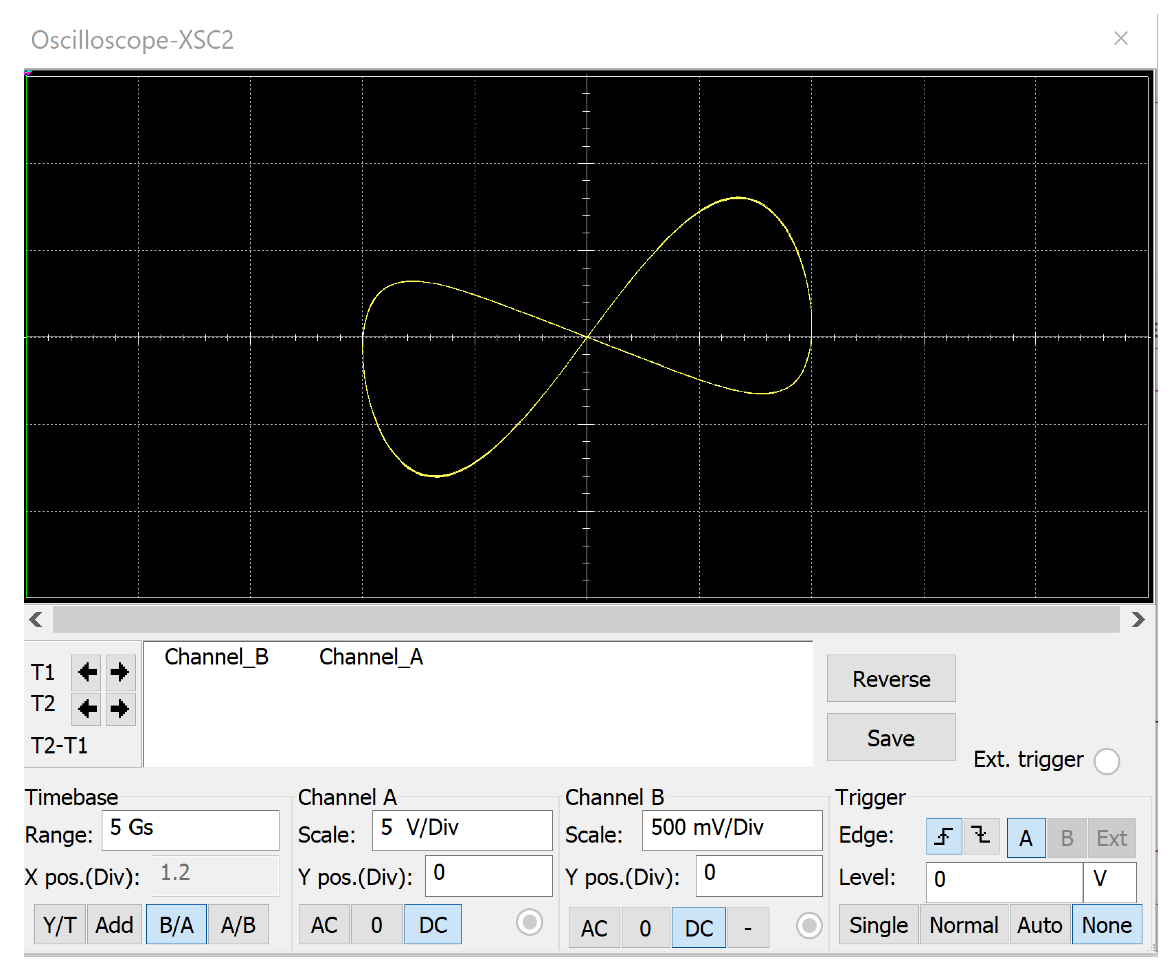
3. Memristor Model
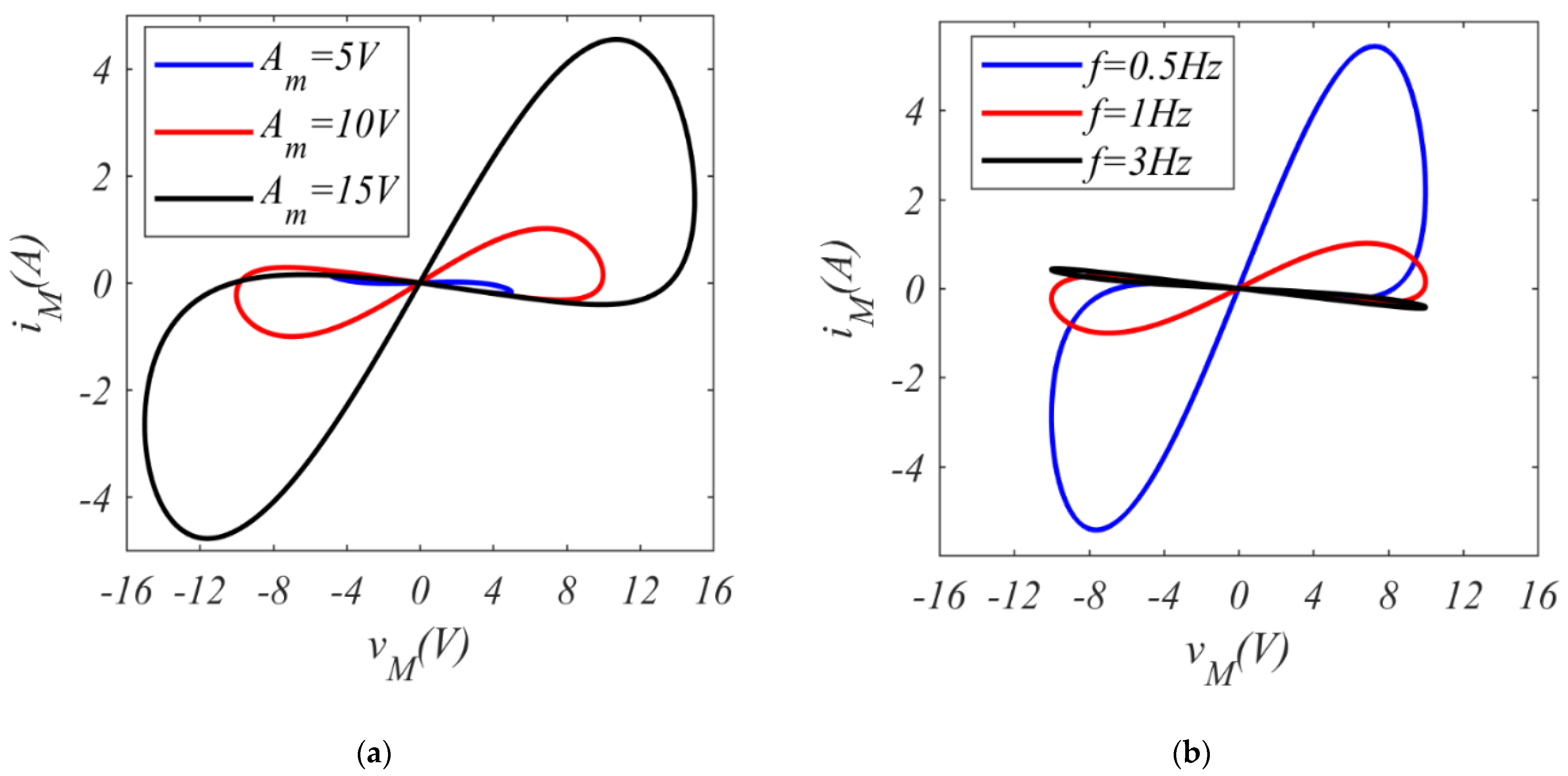
3.1. Integer-Order Case
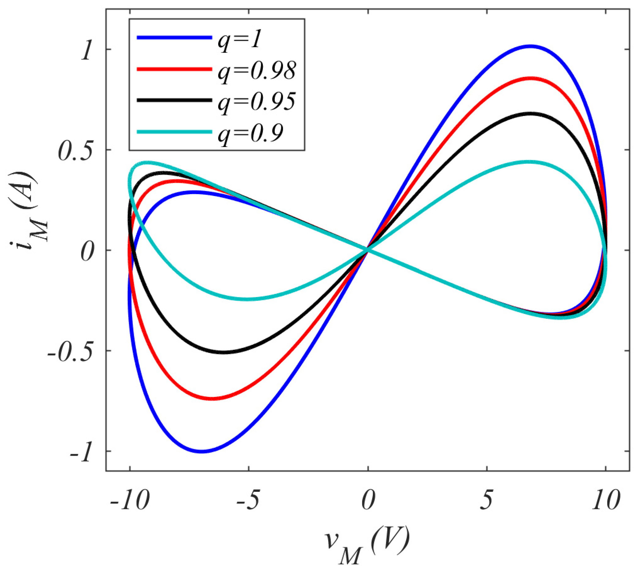
3.2. Fractional-Order Case
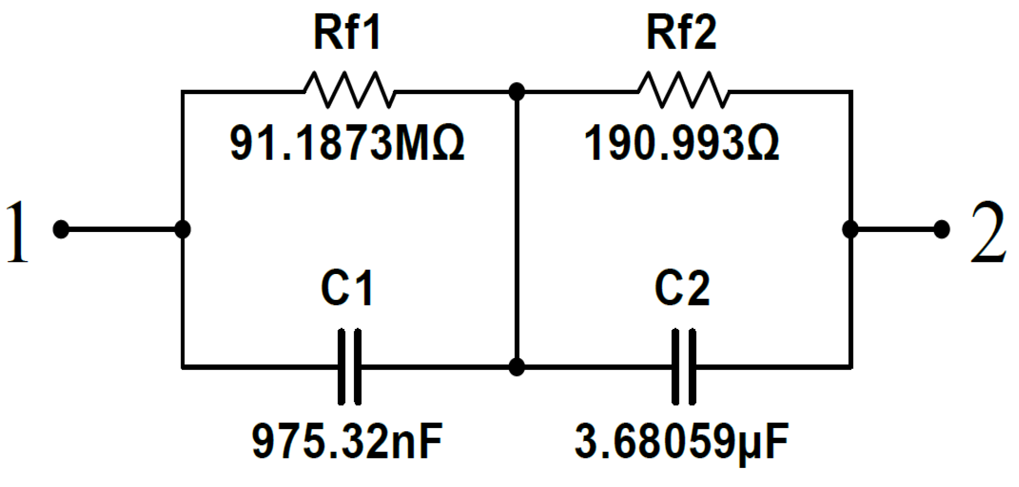
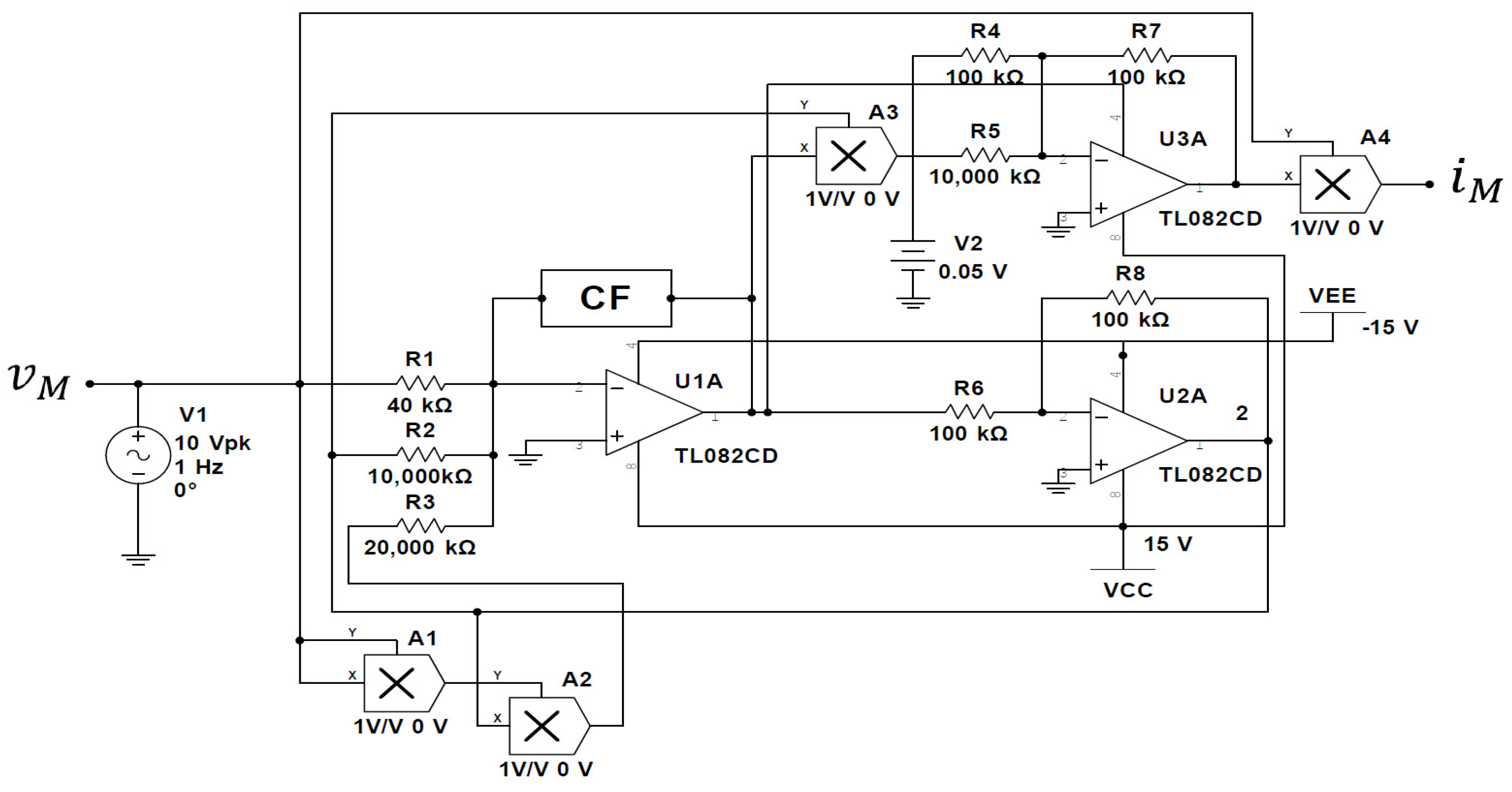
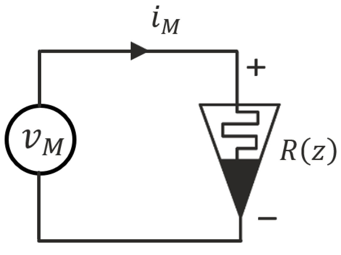
3.3. Circuit Realization of the Fractional-Order Memristor
4. Fractional-Order Memristive-Based Simple Chaotic Circuit
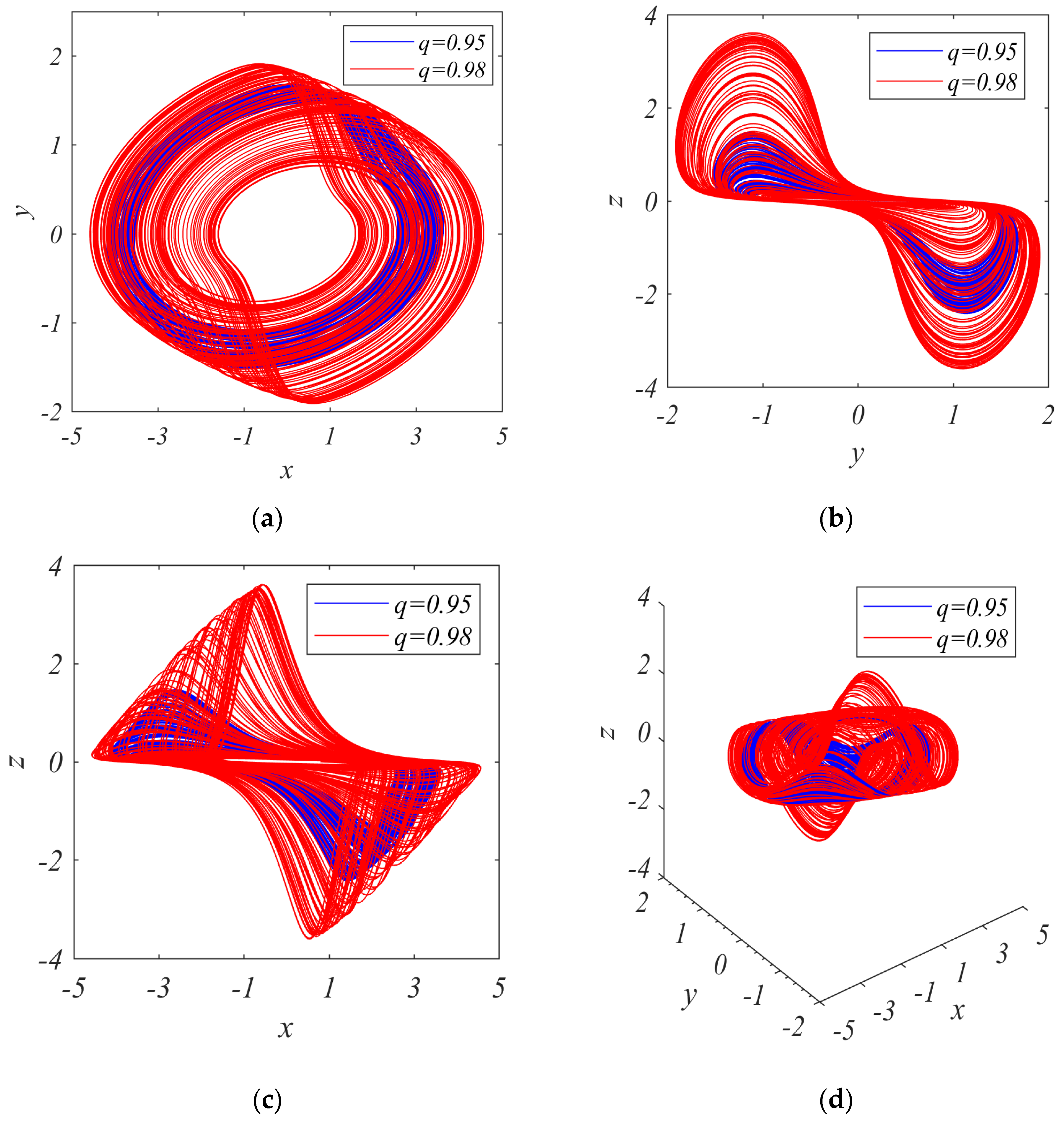
5. Complex Dynamics of the System
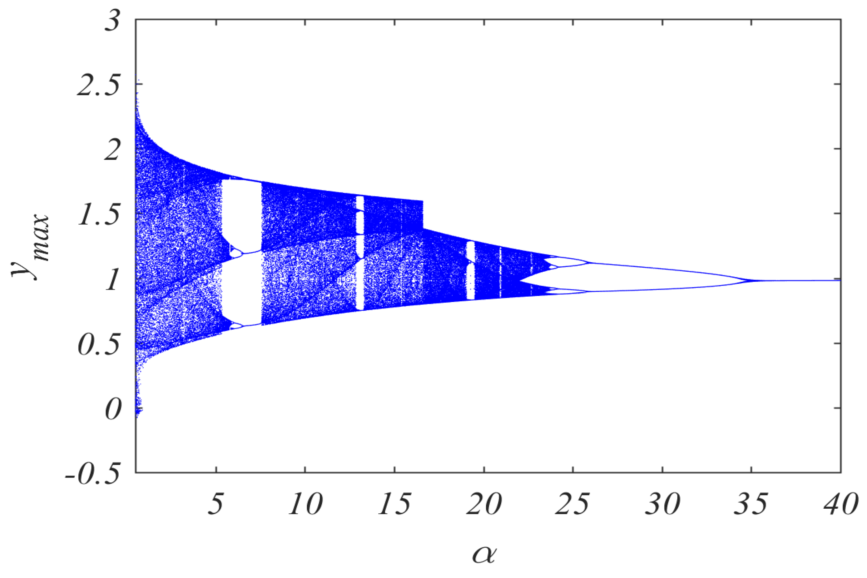
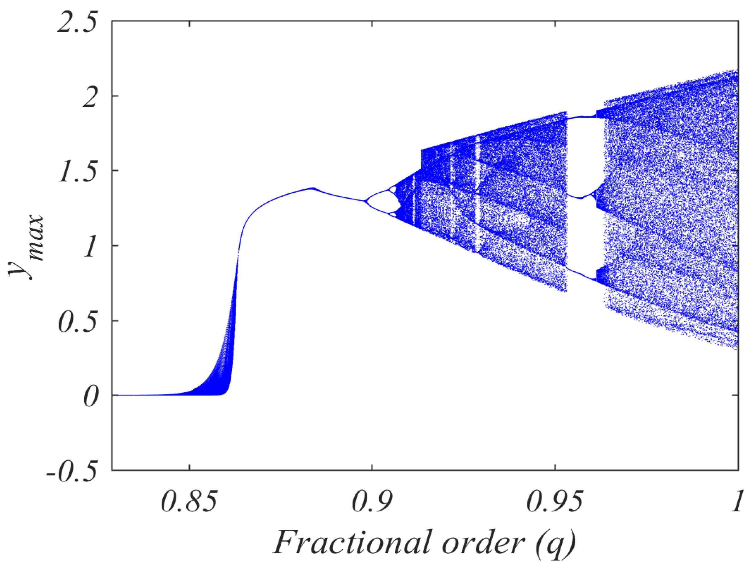
5.1. Bifurcation Diagrams
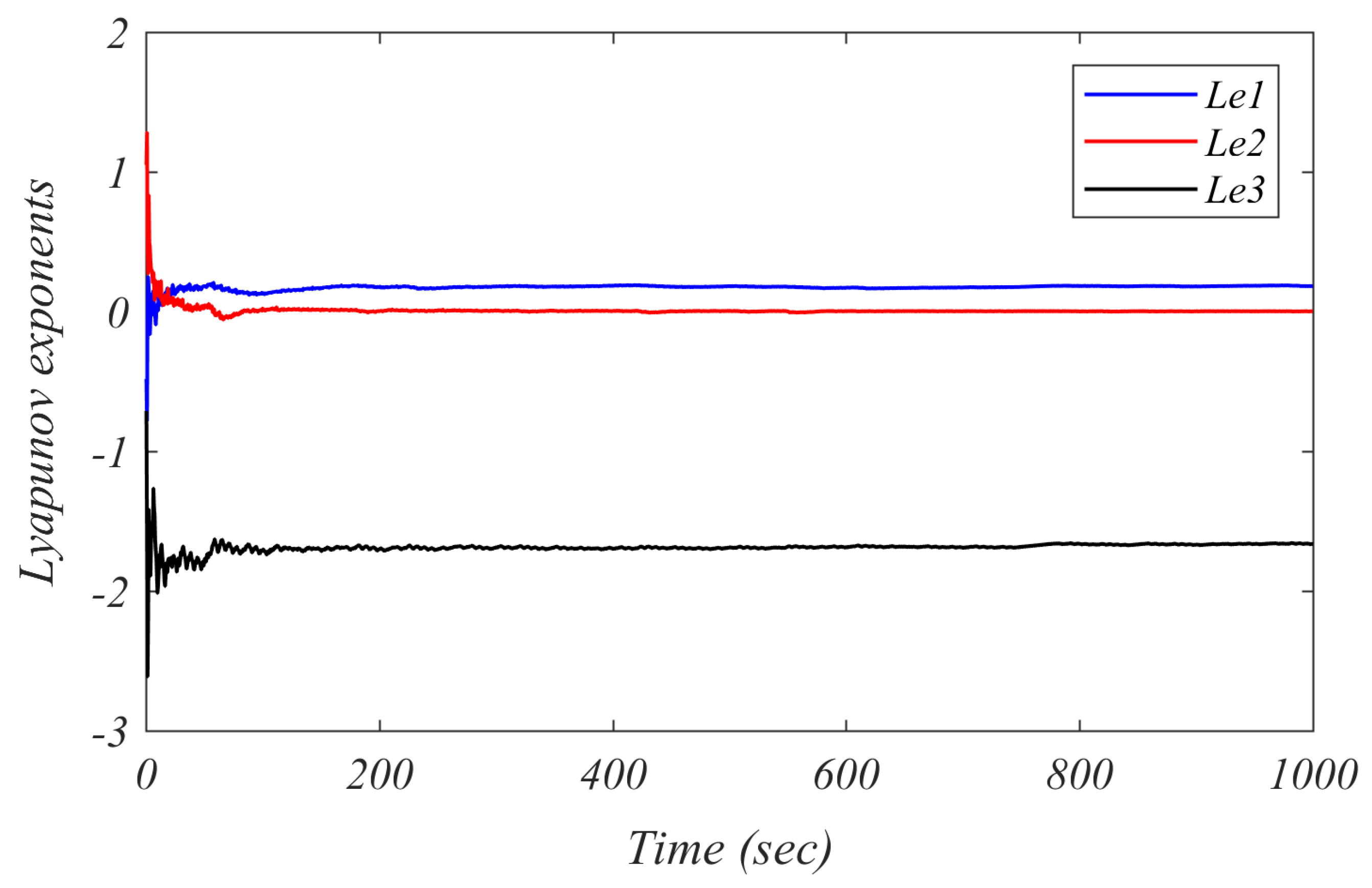
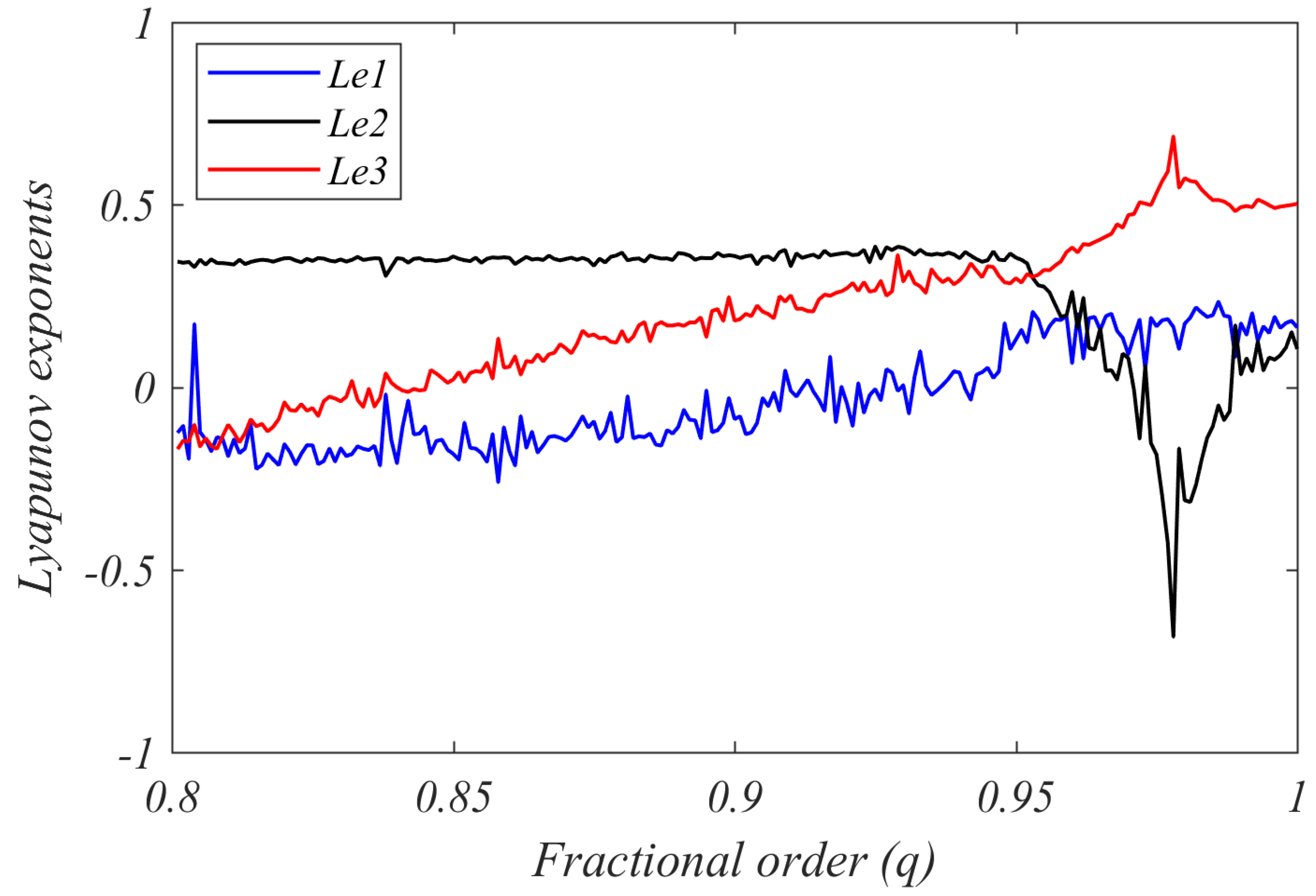
5.2. Lyapunov Exponents
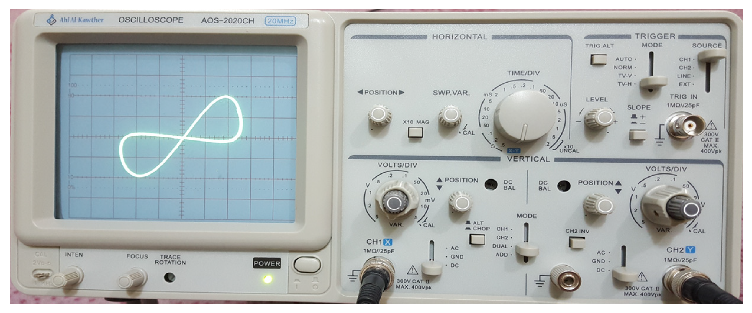
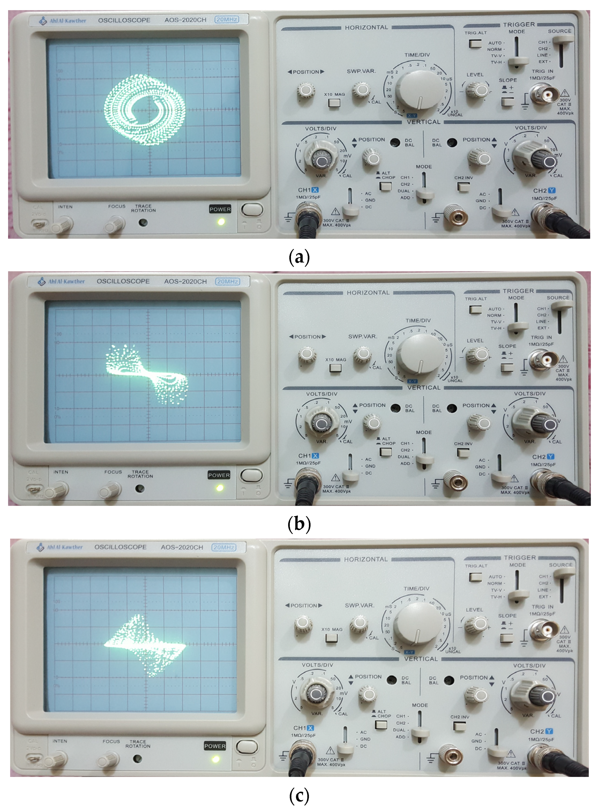
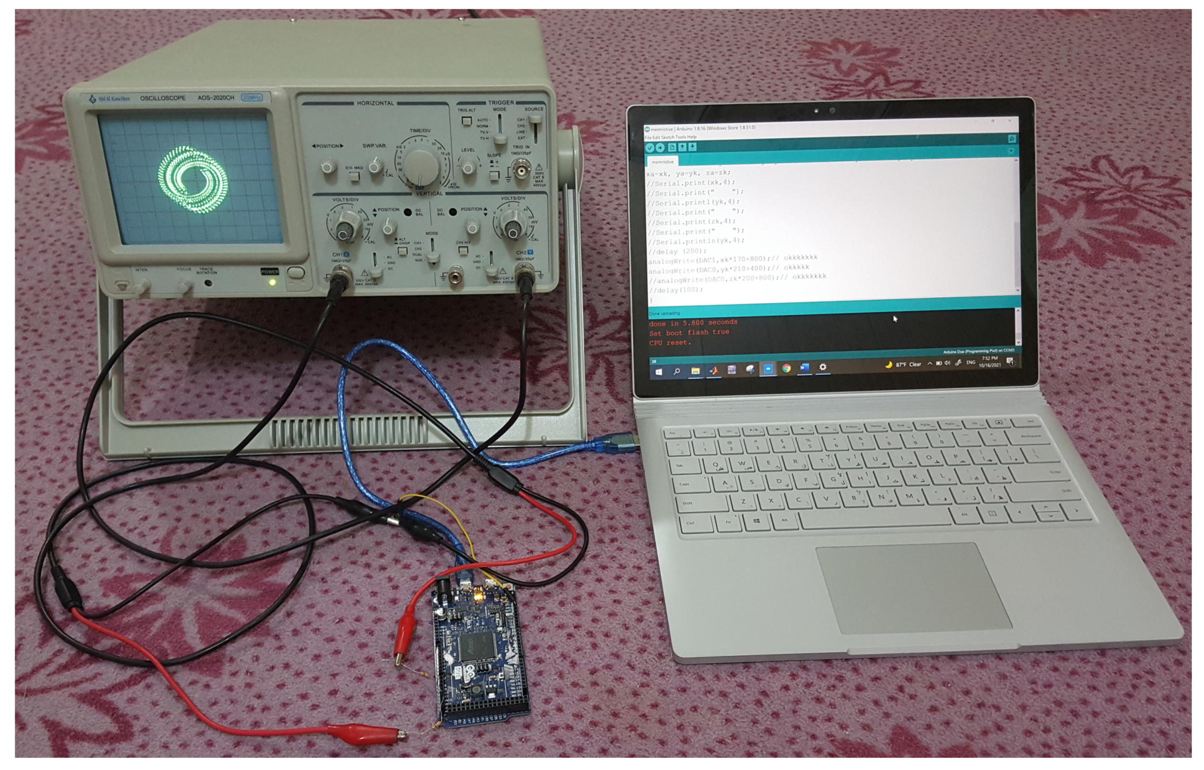
6. Microcontroller Implementation
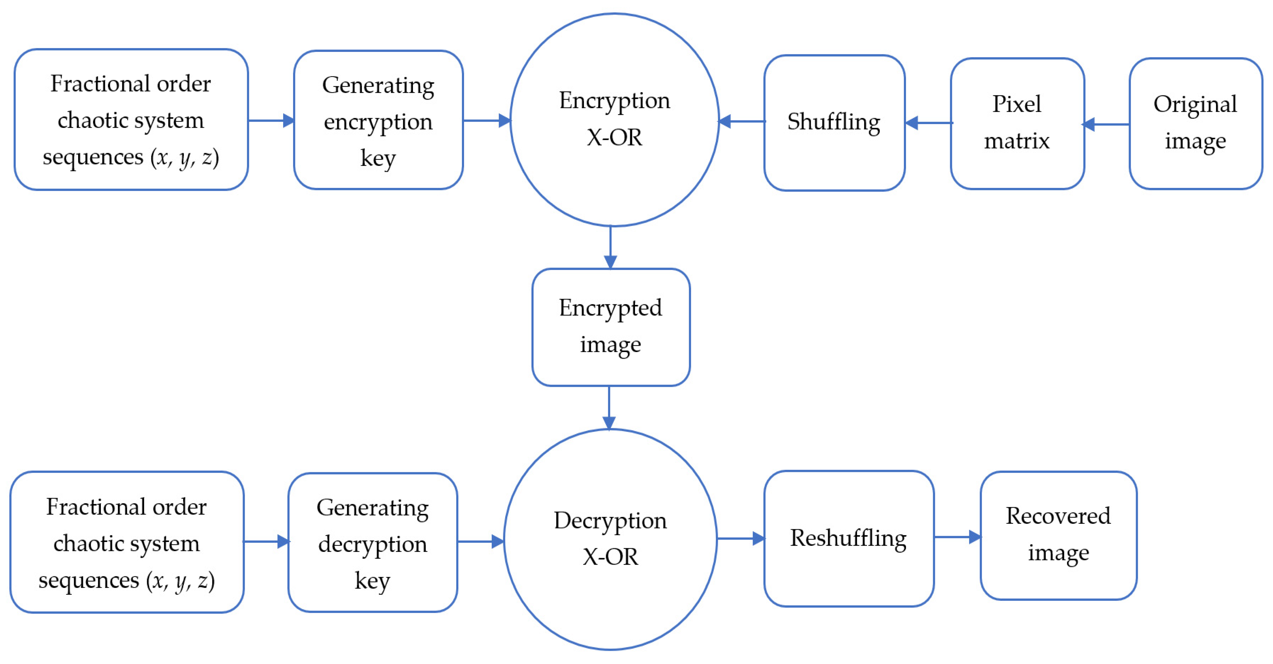
7. Image Encryption Application
- Step 1. Read an original grayscale image to obtain its pixels as grayscale values matrix IM*N (where M and N denote the row and column of the image pixels) and change this matrix to1D vector as I = {I1, I2, …, IMN}.
- Step 2. Before using the obtained grayscale values 1D vector in the encryption process, shuffle this grayscale values 1D vector by arbitrarily moving these values. The histogram will not change as a result of this process, but it will make it more difficult for a burglar to decrypt the image without knowing the exact shuffling method.
- Step 3. Set the initial values of the fractional-order memristive chaotic system (14) (x0, y0, z0), select its fractional order (q), and its parameters (d, g, α, β, a, b, and k).
- Step 4. Simulate the simple fractional-order memristive chaotic system (14), iterate constantly, and randomly choose MN set of solutions to generate the chaotic sequence. S = {S1, S2,…, SMN}. (These solution sets are selected randomly from the obtained values of the system (14) variables (x, y, and z)).
- Step 5. To obtain secret keys K = {K1, K2,…, KMN}, preprocess the sequence S = {S1, S2,…, SMN}. These secret keys are gained according to the following mathematical operations applied to the obtained system (14) chaotic sequence in Step 4 [51].
- Step 6. Encrypt the pixels of the original image I = {I1, I2, …, IMN} using the obtained code in step code as:where denotes the XOR process and the E = {E1, E2, … EMN} is the obtained 1D vector representation of the encrypted image.
- Step 7. Reform the 1D encrypted vector E = {E1, E2, … EMN} to obtain 2D pixels of the encrypted image.
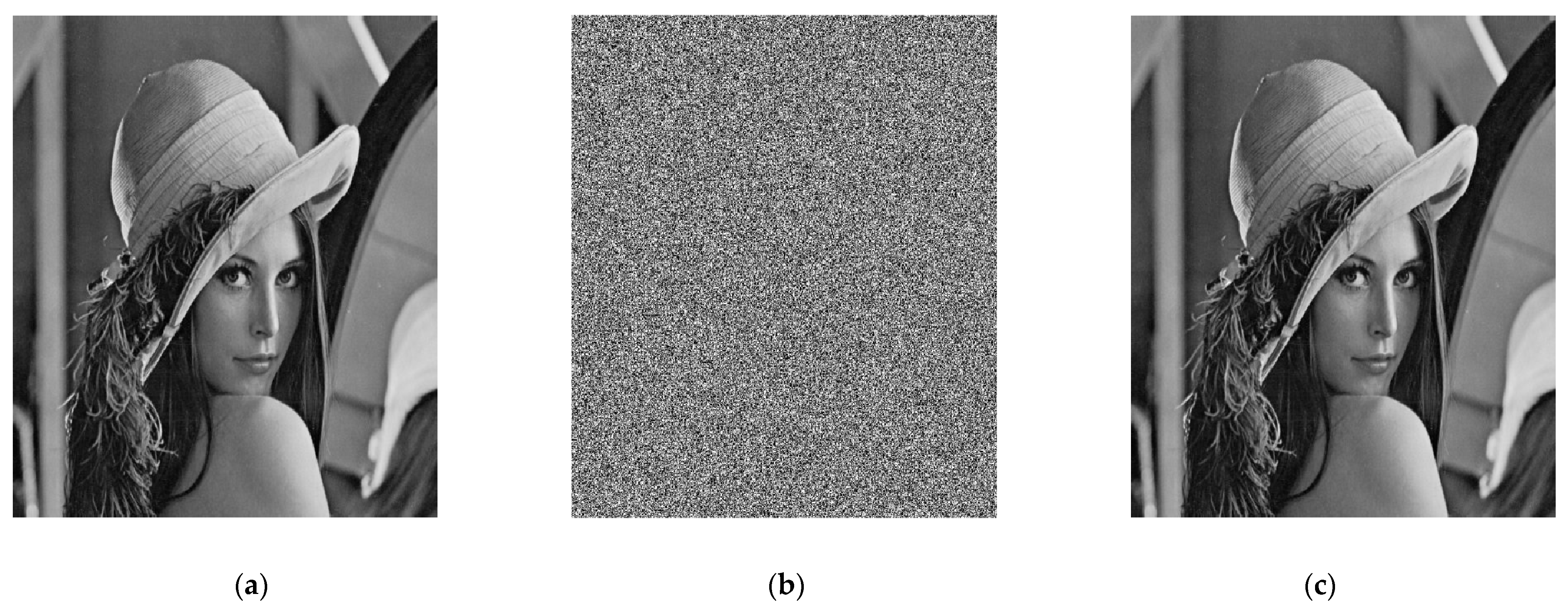
8. Numerical Simulation Results
9. Cryptanalysis
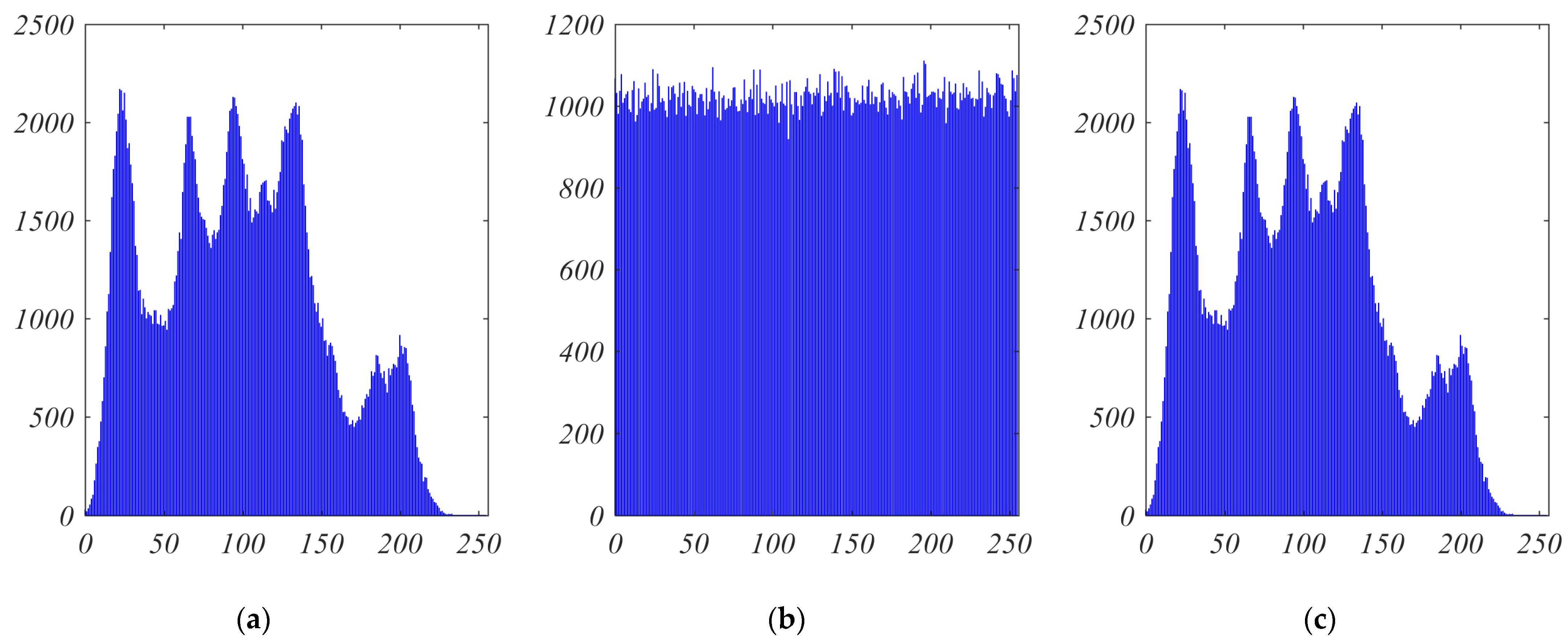
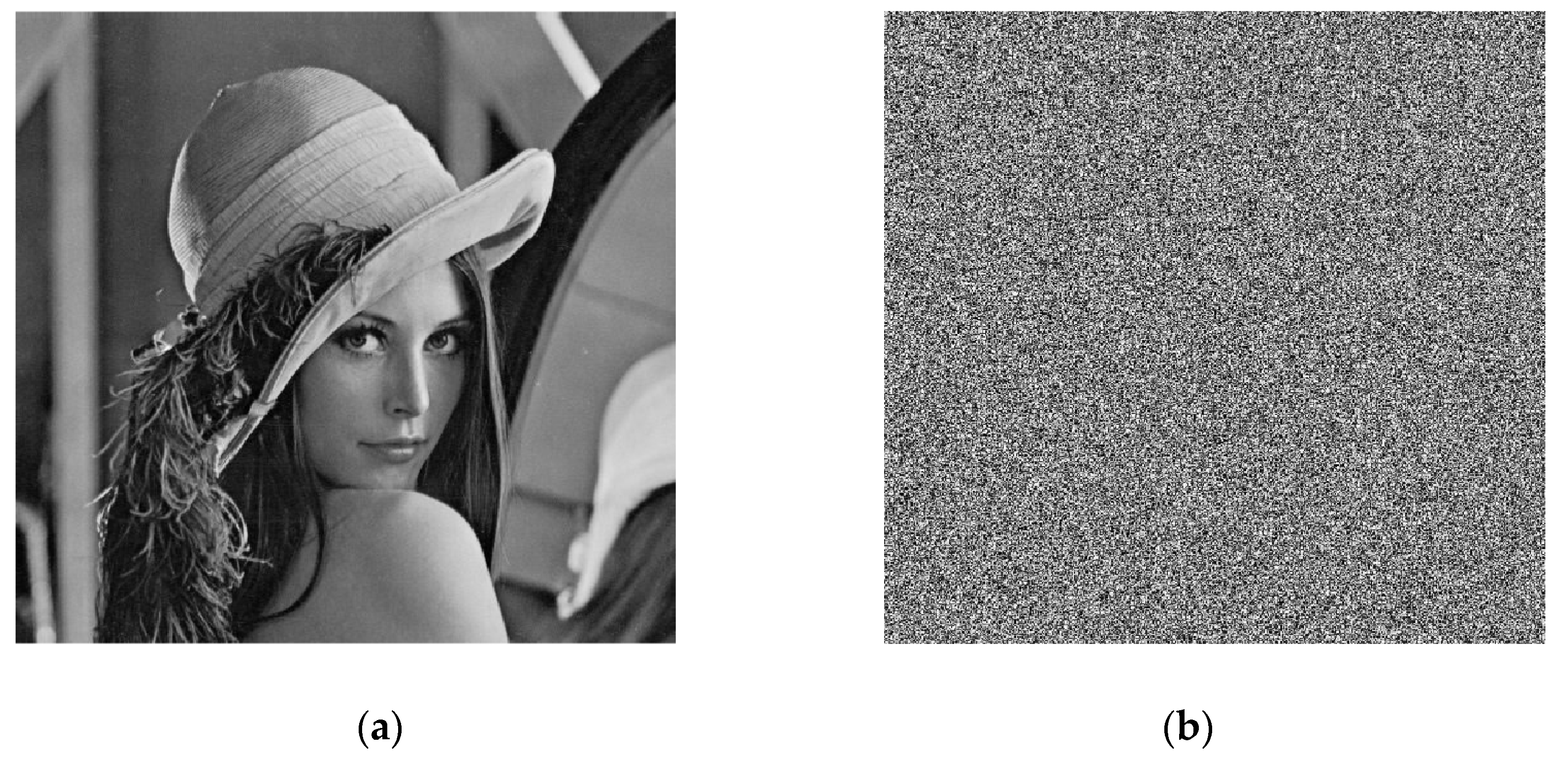
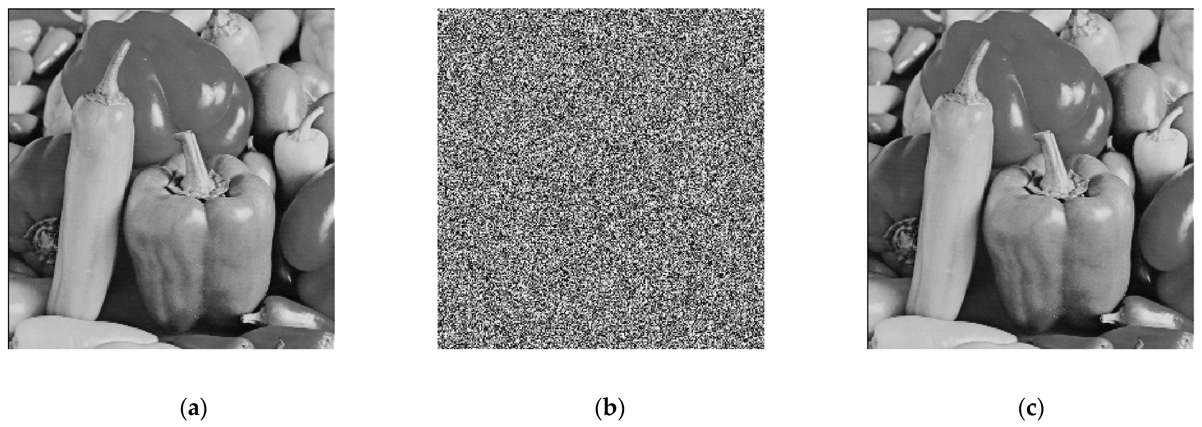
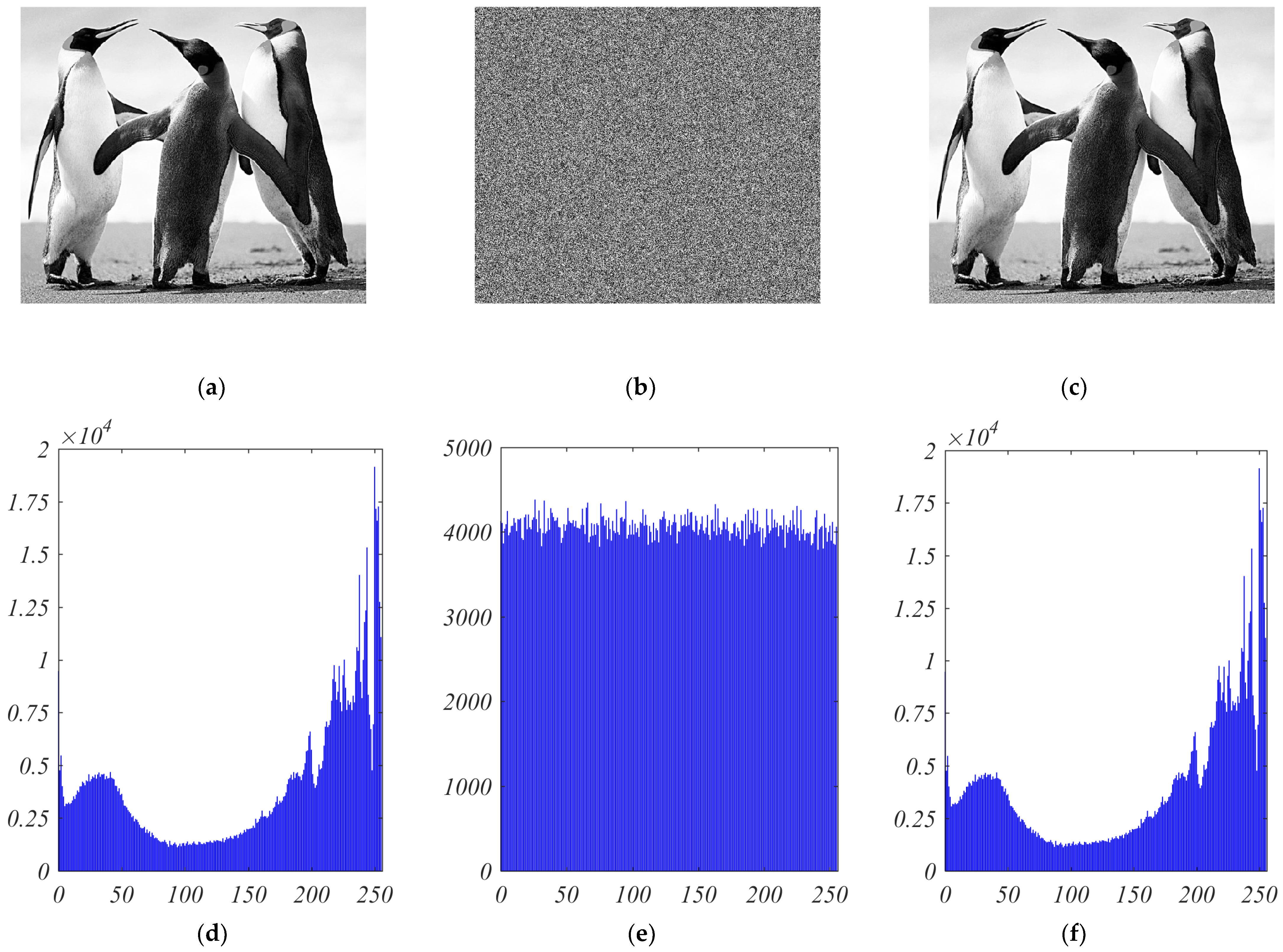
9.1. Histogram Analysis
9.2. Keyspace Analysis
9.3. Key Sensitivity Analysis
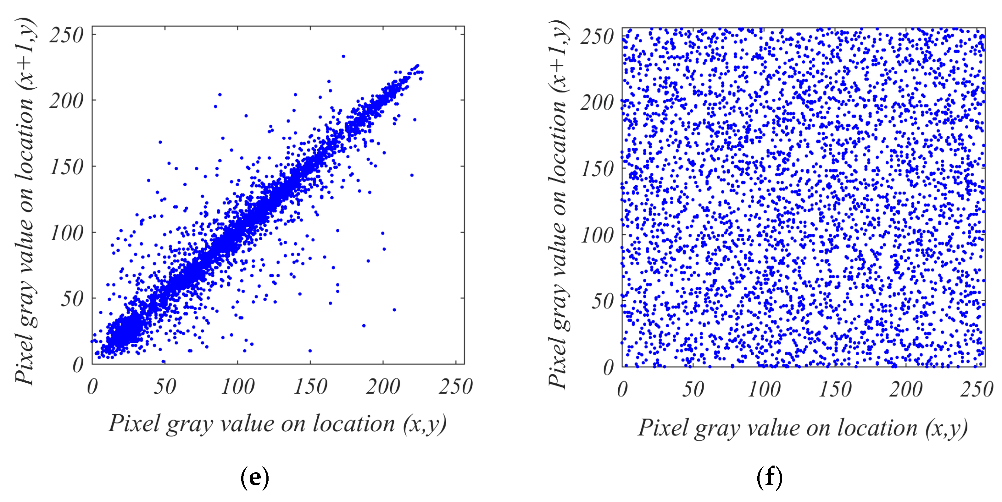
9.4. Correlation Analysis
9.5. Entropy Analysis
9.6. Time Efficiency Analysis
9.7. Comparison Summary
10. Conclusions
Author Contributions
Funding
Conflicts of Interest
References
- Meng-Lewis, Y.; Wong, D.; Zhao, Y.; Lewis, G. Understanding complexity and dynamics in the career development of eSports athletes. Sport Manag. Rev. 2021. [Google Scholar] [CrossRef]
- Rahman, Z.-A.S.A.; Jasim, B.H.; Al-Yasir, Y.I.A.; Hu, Y.-F.; Abd-Alhameed, R.A.; Alhasnawi, B.N. A New Fractional-Order Chaotic System with Its Analysis, Synchronization, and Circuit Realization for Secure Communication Applications. Mathematics 2021, 9, 2593. [Google Scholar] [CrossRef]
- Mahmoud, E.E.; Trikha, P.; Jahanzaib, L.S.; Almaghrabi, O.A. Dynamical analysis and chaos control of the fractional chaotic ecological model. Chaos Solitons Fractals 2020, 141, 110348. [Google Scholar] [CrossRef]
- Liao, T.-L.; Chen, H.-C.; Peng, C.-Y.; Hou, Y.-Y. Chaos-based secure communications in biomedical information application. Electronics 2021, 10, 359. [Google Scholar] [CrossRef]
- Rahman, Z.-A.S.A.; Jasim, B.H.; Al-Yasir, Y.I.A.; Abd-Alhameed, R.A.; Alhasnawi, B.N. A New No Equilibrium Fractional Order Chaotic System, Dynamical Investigation, Synchronization, and Its Digital Implementation. Inventions 2021, 6, 49. [Google Scholar] [CrossRef]
- Vaidyanathan, S.; Volos, C. Advances in Memristors, Memristive Devices and Systems; Springer: Berlin/Heidelberg, Germany, 2017; Volume 701. [Google Scholar]
- Rahma, F.; Muneam, S. Memristive Nonlinear Electronic Circuits: Dynamics, Synchronization and Applications; Springer: Berlin/Heidelberg, Germany, 2019. [Google Scholar]
- Shen, Y.; Wang, G. History Erase Effect of Real Memristors. Electronics 2021, 10, 303. [Google Scholar] [CrossRef]
- Peng, Y.; He, S.; Sun, K. A higher dimensional chaotic map with discrete memristor. AEU-Int. J. Electron. Commun. 2021, 129, 153539. [Google Scholar] [CrossRef]
- Akgül, A.; Rajagopal, K.; Durdu, A.; Pala, M.A.; Boyraz, Ö.F.; Yildiz, M.Z. A simple fractional-order chaotic system based on memristor and memcapacitor and its synchronization application. Chaos Solitons Fractals 2021, 152, 111306. [Google Scholar] [CrossRef]
- Zhou, L.; Wang, C.; Zhou, L. Generating four-wing hyperchaotic attractor and two-wing, three-wing, and four-wing chaotic attractors in 4D memristive system. Int. J. Bifurc. Chaos 2017, 27, 1750027. [Google Scholar] [CrossRef]
- Lozynskyy, A.; Chaban, A.; Perzyński, T.; Szafraniec, A.; Kasha, L. Application of Fractional-Order Calculus to Improve the Mathematical Model of a Two-Mass System with a Long Shaft. Energies 2021, 14, 1854. [Google Scholar] [CrossRef]
- Rahman, Z.-A.S.A.; Jassim, B.H.; Al-Yasir, Y.I.A. New Fractional Order Chaotic System: Analysis, Synchronization, and it’s Application. Iraqi J. Electr. Electron. Eng. 2021, 17, 116–123. [Google Scholar] [CrossRef]
- Yang, C.; Xie, F.; Chen, Y.; Xiao, W.; Zhang, B. Modeling and analysis of the fractional-order flyback converter in continuous conduction mode by caputo fractional calculus. Electronics 2020, 9, 1544. [Google Scholar] [CrossRef]
- Tavazoei, M.S. Fractional order chaotic systems: History, achievements, applications, and future challenges. Eur. Phys. J. Spec. Top. 2020, 229, 887–904. [Google Scholar] [CrossRef]
- Tlelo-Cuautle, E.; Pano-Azucena, A.D.; Guillén-Fernández, O.; Silva-Juárez, A. Analog/Digital Implementation of Fractional Order Chaotic Circuits and Applications; Springer: Berlin/Heidelberg, Germany, 2020. [Google Scholar]
- Yang, F.; Mou, J.; Ma, C.; Cao, Y. Dynamic analysis of an improper fractional-order laser chaotic system and its image encryption application. Opt. Lasers Eng. 2020, 129, 106031. [Google Scholar] [CrossRef]
- Wen, H.; Zhang, C.; Huang, L.; Ke, J.; Xiong, D. Security Analysis of a Color Image Encryption Algorithm Using a Fractional-Order Chaos. Entropy 2021, 23, 258. [Google Scholar] [CrossRef] [PubMed]
- Alanazi, A.S.; Munir, N.; Khan, M.; Asif, M.; Hussain, I. Cryptanalysis of Novel Image Encryption Scheme Based on Multiple Chaotic Substitution Boxes. IEEE Access 2021, 9, 93795–93802. [Google Scholar] [CrossRef]
- Askar, S.; Al-Khedhairi, A.; Elsonbaty, A.; Elsadany, A. Chaotic Discrete Fractional-Order Food Chain Model and Hybrid Image Encryption Scheme Application. Symmetry 2021, 13, 161. [Google Scholar] [CrossRef]
- Xian, Y.; Wang, X. Fractal sorting matrix and its application on chaotic image encryption. Inf. Sci. 2021, 547, 1154–1169. [Google Scholar] [CrossRef]
- Ding, L.; Ding, Q. A Novel Image Encryption Scheme Based on 2D Fractional Chaotic Map, DWT and 4D Hyper-chaos. Electronics 2020, 9, 1280. [Google Scholar] [CrossRef]
- Zhu, S.; Wang, G.; Zhu, C. A secure and fast image encryption scheme based on double chaotic S-boxes. Entropy 2019, 21, 790. [Google Scholar] [CrossRef] [Green Version]
- Ma, X.; Mou, J.; Liu, J.; Ma, C.; Yang, F.; Zhao, X. A novel simple chaotic circuit based on memristor-memcapacitor. Nonlinear Dyn. 2020, 100, 2859–2876. [Google Scholar] [CrossRef]
- Baleanu, D.; Fernandez, A. On fractional operators and their classifications. Mathematics 2019, 7, 830. [Google Scholar] [CrossRef] [Green Version]
- Sabatier, J.; Agrawal, O.P.; Machado, J.A.T. Advances in Fractional Calculus; Springer: Berlin/Heidelberg, Germany, 2007; Volume 4. [Google Scholar]
- Oprzędkiewicz, K.; Rosół, M.; Żegleń-Włodarczyk, J. The Frequency and Real-Time Properties of the Microcontroller Implementation of Fractional-Order PID Controller. Electronics 2021, 10, 524. [Google Scholar] [CrossRef]
- Kozioł, K.; Stanisławski, R.; Bialic, G. Fractional-order sir epidemic model for transmission prediction of COVID-19 disease. Appl. Sci. 2020, 10, 8316. [Google Scholar] [CrossRef]
- Khan, H.; Shah, R.; Baleanu, D.; Kumam, P.; Arif, M. Analytical solution of fractional-order hyperbolic telegraph equation, using natural transform decomposition method. Electronics 2019, 8, 1015. [Google Scholar] [CrossRef] [Green Version]
- Jiang, Y.; Zhang, B. Comparative study of Riemann-liouville and caputo derivative definitions in time-domain analysis of fractional-order capacitor. IEEE Trans. Circuits Syst. II Express Briefs 2019, 67, 2184–2188. [Google Scholar] [CrossRef]
- Rahman, Z.-A.S.A.; Al-Kashoash, H.A.A.; Ramadhan, S.M.; Al-Yasir, Y.I.A. Adaptive control synchronization of a novel memristive chaotic system for secure communication applications. Inventions 2019, 4, 30. [Google Scholar] [CrossRef] [Green Version]
- Buscarino, A.; Fortuna, L.; Frasca, M.; Gambuzza, L.V. A gallery of chaotic oscillators based on HP memristor. Int. J. Bifurc. Chaos 2013, 23, 1330015. [Google Scholar] [CrossRef]
- Ascoli, A.; Corinto, F.; Senger, V.; Tetzlaff, R. Memristor model comparison. IEEE Circuits Syst. Mag. 2013, 13, 89–105. [Google Scholar] [CrossRef]
- Guo, Q.; Wang, N.; Zhang, G. A novel current-controlled memristor-based chaotic circuit. Integration 2021, 80, 20–28. [Google Scholar] [CrossRef]
- Tahir, F.R.; Ramadhan, S.M. Analog programmable circuit implementation for memristor. Iraqi J. Electr. Electron. Eng. 2018, 14, 1–9. [Google Scholar] [CrossRef]
- Liu, Y.; Pu, Y.-F.; Shen, X.-D.; Zhou, J.-L. Design of 1/2 (n) order analog fractance approximation circuit based on continued fractions decomposition. J. Sichuan Univ. Eng. Sci. Ed. 2012, 44, 153–158. [Google Scholar]
- Hammouch, Z.; Mekkaoui, T. Circuit design and simulation for the fractional-order chaotic behavior in a new dynamical system. Complex Intell. Syst. 2018, 4, 251–260. [Google Scholar] [CrossRef]
- Zouad, F.; Kemih, K.; Hamiche, H. A new secure communication scheme using fractional order delayed chaotic system: Design and electronics circuit simulation. Analog Integr. Circuits Signal Process. 2019, 99, 619–632. [Google Scholar] [CrossRef]
- Hosseinnia, S.H.; Ghaderi, R.; Mahmoudian, M.; Momani, S. Sliding mode synchronization of an uncertain fractional order chaotic system. Comput. Math. Appl. 2010, 59, 1637–1643. [Google Scholar] [CrossRef] [Green Version]
- Munmuangsaen, B.; Srisuchinwong, B. A hidden chaotic attractor in the classical Lorenz system. Chaos Solitons Fractals 2018, 107, 61–66. [Google Scholar] [CrossRef]
- Jasim, B.H.; Hassan, K.H.; Omran, K.M. A new 4-D hyperchaotic hidden attractor system: Its dynamics, coexisting attractors, synchronization and microcontroller implementation. Int. J. Electr. Comput. Eng. 2021, 11, 2068–2078. [Google Scholar] [CrossRef]
- Mouelas, A.N.; Fozin, T.F.; Kengne, R.; Kengne, J.; Fotsin, H.B.; Essimbi, B.Z. Extremely rich dynamical behaviors in a simple nonautonomous Jerk system with generalized nonlinearity: Hyperchaos, intermittency, offset-boosting and multistability. Int. J. Dyn. Control 2020, 8, 51–69. [Google Scholar] [CrossRef]
- Garrappa, R. Numerical solution of fractional differential equations: A survey and a software tutorial. Mathematics 2018, 6, 16. [Google Scholar] [CrossRef] [Green Version]
- Al-Hussein, A.-B.A.; Tahir, F.R.; Ouannas, A.; Sun, T.-C.; Jahanshahi, H.; Aly, A.A. Chaos Suppressing in a Three-Buses Power System Using an Adaptive Synergetic Control Method. Electronics 2021, 10, 1532. [Google Scholar] [CrossRef]
- Jasim, B.H.; Mjily, A.H.; Al-Aaragee, A.M.J. A novel 4 dimensional hyperchaotic system with its control, synchronization and implementation. Int. J. Electr. Comput. Eng. 2021, 11, 2974–2985. [Google Scholar] [CrossRef]
- Sánchez-López, C. An experimental synthesis methodology of fractional-order chaotic attractors. Nonlinear Dyn. 2020, 100, 3907–3923. [Google Scholar] [CrossRef]
- Kondaveeti, H.K.; Kumaravelu, N.K.; Vanambathina, S.D.; Mathe, S.E.; Vappangi, S. A systematic literature review on prototyping with Arduino: Applications, challenges, advantages, and limitations. Comput. Sci. Rev. 2021, 40, 100364. [Google Scholar] [CrossRef]
- Soler-Llorens, J.L.; Galiana-Merino, J.J.; Nassim-Benabdeloued, B.Y.; Rosa-Cintas, S.; Zamora, J.O.; Giner-Caturla, J.J. Design and implementation of an Arduino-based plug-and-play acquisition system for seismic noise measurements. Electronics 2019, 8, 1035. [Google Scholar] [CrossRef] [Green Version]
- Zamora-Arellano, F.; López-Bonilla, O.R.; García-Guerrero, E.E.; Olguín-Tiznado, J.E.; Inzunza-González, E.; López-Mancilla, D.; Tlelo-Cuautle, E. Development of a Portable, Reliable and Low-Cost Electrical Impedance Tomography System Using an Embedded System. Electronics 2021, 10, 15. [Google Scholar] [CrossRef]
- Masood, F.; Boulila, W.; Ahmad, J.; Sankar, S.; Rubaiee, S.; Buchanan, W.J. A novel privacy approach of digital aerial images based on mersenne twister method with DNA genetic encoding and chaos. Remote Sens. 2020, 12, 1893. [Google Scholar] [CrossRef]
- Xu, Y.; Wang, H.; Li, Y.; Pei, B. Image encryption based on synchronization of fractional chaotic systems. Commun. Nonlinear Sci. Numer. Simul. 2014, 19, 3735–3744. [Google Scholar] [CrossRef]
- Lin, C.-Y.; Wu, J.-L. Cryptanalysis and improvement of a chaotic map-based image encryption system using both plaintext related permutation and diffusion. Entropy 2020, 22, 589. [Google Scholar] [CrossRef] [PubMed]
- Xiang, Y.; Xiao, D.; Zhang, R.; Liang, J.; Liu, R. Cryptanalysis and improvement of a reversible data-hiding scheme in encrypted images by redundant space transfer. Inf. Sci. 2021, 545, 188–206. [Google Scholar] [CrossRef]
- El-Latif, A.A.A.; Abd-El-Atty, B.; Belazi, A.; Iliyasu, A.M. Efficient Chaos-Based Substitution-Box and Its Application to Image Encryption. Electronics 2021, 10, 1392. [Google Scholar] [CrossRef]
- ElKamchouchi, D.H.; Mohamed, H.G.; Moussa, K.H. A bijective image encryption system based on hybrid chaotic map diffusion and DNA confusion. Entropy 2020, 22, 180. [Google Scholar] [CrossRef] [PubMed] [Green Version]
- Yousif, B.; Khalifa, F.; Makram, A.; Takieldeen, A. A novel image encryption/decryption scheme based on integrating multiple chaotic maps. AIP Adv. 2020, 10, 75220. [Google Scholar] [CrossRef]
- Hou, W.; Li, S.; He, J.; Ma, Y. A Novel Image-Encryption Scheme Based on a Non-Linear Cross-Coupled Hyperchaotic System with the Dynamic Correlation of Plaintext Pixels. Entropy 2020, 22, 779. [Google Scholar] [CrossRef] [PubMed]
- Wang, X.; Li, Y.; Jin, J. A new one-dimensional chaotic system with applications in image encryption. Chaos Solitons Fractals 2020, 139, 110102. [Google Scholar] [CrossRef]
- Kari, A.P.; Navin, A.H.; Bidgoli, A.M.; Mirnia, M. A new image encryption scheme based on hybrid chaotic maps. Multimed. Tools Appl. 2021, 80, 2753–2772. [Google Scholar] [CrossRef]
- Wang, X.; Teng, L.; Qin, X. A novel colour image encryption algorithm based on chaos. Signal Process. 2012, 92, 1101–1108. [Google Scholar] [CrossRef]
- Chen, G.; Mao, Y.; Chui, C.K. A symmetric image encryption scheme based on 3D chaotic cat maps. Chaos Solitons Fractals 2004, 21, 749–761. [Google Scholar] [CrossRef]
- Tlelo-Cuautle, E.; Díaz-Muñoz, J.D.; González-Zapata, A.M.; Li, R.; León-Salas, W.D.; Fernández, F.V.; Guillén-Fernández, O.; Cruz-Vega, I. Chaotic image encryption using hopfield and hindmarsh–rose neurons implemented on FPGA. Sensors 2020, 20, 1326. [Google Scholar] [CrossRef] [PubMed] [Green Version]
- Peng, X.; Zeng, Y. Image encryption application in a system for compounding self-excited and hidden attractors. Chaos Solitons Fractals 2020, 139, 110044. [Google Scholar] [CrossRef]
- Vaseghi, B.; Hashemi, S.S.; Mobayen, S.; Fekih, A. Finite time chaos synchronization in time-delay channel and its application to satellite image encryption in OFDM communication systems. IEEE Access 2021, 9, 21332–21344. [Google Scholar] [CrossRef]
- Hafsa, A.; Sghaier, A.; Malek, J.; Machhout, M. Image encryption method based on improved ECC and modified AES algorithm. Multimed. Tools Appl. 2021, 80, 19769–19801. [Google Scholar] [CrossRef]


| Figure 9 | Figure 10 | ||
|---|---|---|---|
| Parameter | Value | Parameter | Value |
| d | 4 | d | 4 |
| g | 0.5 | g | 0.5 |
| α | Variable | α | 1 |
| β | 1 | β | 1 |
| a | 0.25 | a | 0.25 |
| b | 5 | b | 5 |
| k | 4 | k | 4 |
| fractional order (q) | 0.98 | fractional order (q) | Variable |
| x0 | 0.8 | x0 | 0.8 |
| y0 | 0.8 | y0 | 0.8 |
| z0 | 0 | z0 | 0 |
| Figure 11 | Figure 12 | ||
|---|---|---|---|
| Parameter | Value | Parameter | Value |
| d | 4 | d | 4 |
| g | 0.5 | g | 0.5 |
| α | 1 | α | 1 |
| β | 1 | β | 1 |
| a | 0.25 | a | 0.25 |
| b | 5 | b | 5 |
| k | 4 | k | 4 |
| fractional order (q) | 0.98 | fractional order (q) | Variable |
| x0 | 0.8 | x0 | 0.8 |
| y0 | 0.8 | y0 | 0.8 |
| z0 | 0 | z0 | 0 |
| Direction | Original Image | Encrypted Image |
|---|---|---|
| Vertical | 0.97241 | 0.00032 |
| Horizontal | 0.98671 | 0.00054 |
| Diagonal | 0.96181 | 0.00011 |
| Algorithm | Key Space | NPCR | UACI | Vertical rxy | Horizontal rxy | Diagonal rxy | H(s) | Time Efficiency |
|---|---|---|---|---|---|---|---|---|
| Ref. [19] | 2449 | 0.99606 | 0.33489 | 0.0002 | 0.0046 | 0.0005 | 7.9951 | 0.9 s |
| Ref. [20] | 2530 | 0.99640 | 0.33537 | - | - | - | 7.9978 | - |
| Ref. [21] | 2154 | 99.6096 | 0.33459 | 0.000333 | 0.000524 | 0.000872 | 7.9993 | 0.3261 s |
| Ref. [22] | 2598 | 0.9955 | 0.3325 | 0.0059 | 0.0082 | 0.0007 | 7.9866 | 1.02 s |
| Ref. [23] | 2285 | 0.9964 | 0.3355 | 0.000312 | 0.002088 | 0.001444 | 7.9976 | 1.708 s |
| Ours | 2648 | 0.99866 | 0.49963 | 0.00032 | 0.00054 | 0.00011 | 7.9993 | 0.3 s |
Publisher’s Note: MDPI stays neutral with regard to jurisdictional claims in published maps and institutional affiliations. |
© 2021 by the authors. Licensee MDPI, Basel, Switzerland. This article is an open access article distributed under the terms and conditions of the Creative Commons Attribution (CC BY) license (https://creativecommons.org/licenses/by/4.0/).
Share and Cite
Rahman, Z.-A.S.A.; Jasim, B.H.; Al-Yasir, Y.I.A.; Abd-Alhameed, R.A. High-Security Image Encryption Based on a Novel Simple Fractional-Order Memristive Chaotic System with a Single Unstable Equilibrium Point. Electronics 2021, 10, 3130. https://doi.org/10.3390/electronics10243130
Rahman Z-ASA, Jasim BH, Al-Yasir YIA, Abd-Alhameed RA. High-Security Image Encryption Based on a Novel Simple Fractional-Order Memristive Chaotic System with a Single Unstable Equilibrium Point. Electronics. 2021; 10(24):3130. https://doi.org/10.3390/electronics10243130
Chicago/Turabian StyleRahman, Zain-Aldeen S. A., Basil H. Jasim, Yasir I. A. Al-Yasir, and Raed A. Abd-Alhameed. 2021. "High-Security Image Encryption Based on a Novel Simple Fractional-Order Memristive Chaotic System with a Single Unstable Equilibrium Point" Electronics 10, no. 24: 3130. https://doi.org/10.3390/electronics10243130
APA StyleRahman, Z.-A. S. A., Jasim, B. H., Al-Yasir, Y. I. A., & Abd-Alhameed, R. A. (2021). High-Security Image Encryption Based on a Novel Simple Fractional-Order Memristive Chaotic System with a Single Unstable Equilibrium Point. Electronics, 10(24), 3130. https://doi.org/10.3390/electronics10243130