
Design of Low-Profile Single- and Dual-Band Antennas for IoT Applications


Abstract
1. Introduction
2. Non-Slotted Square Patch
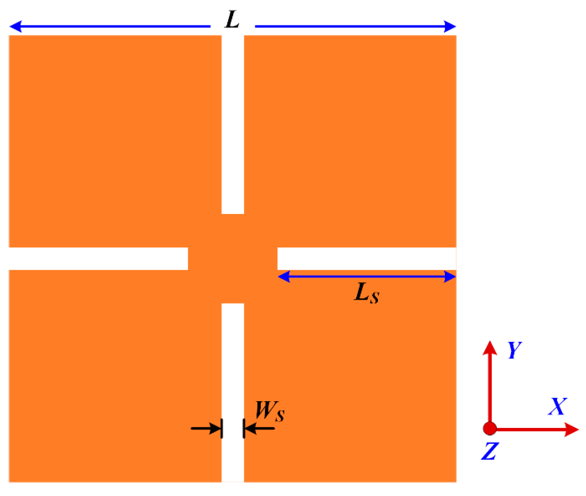
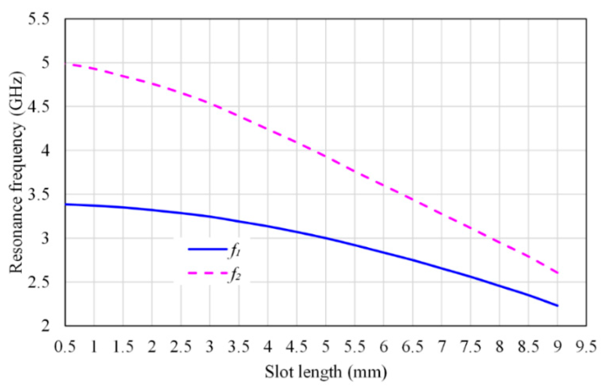
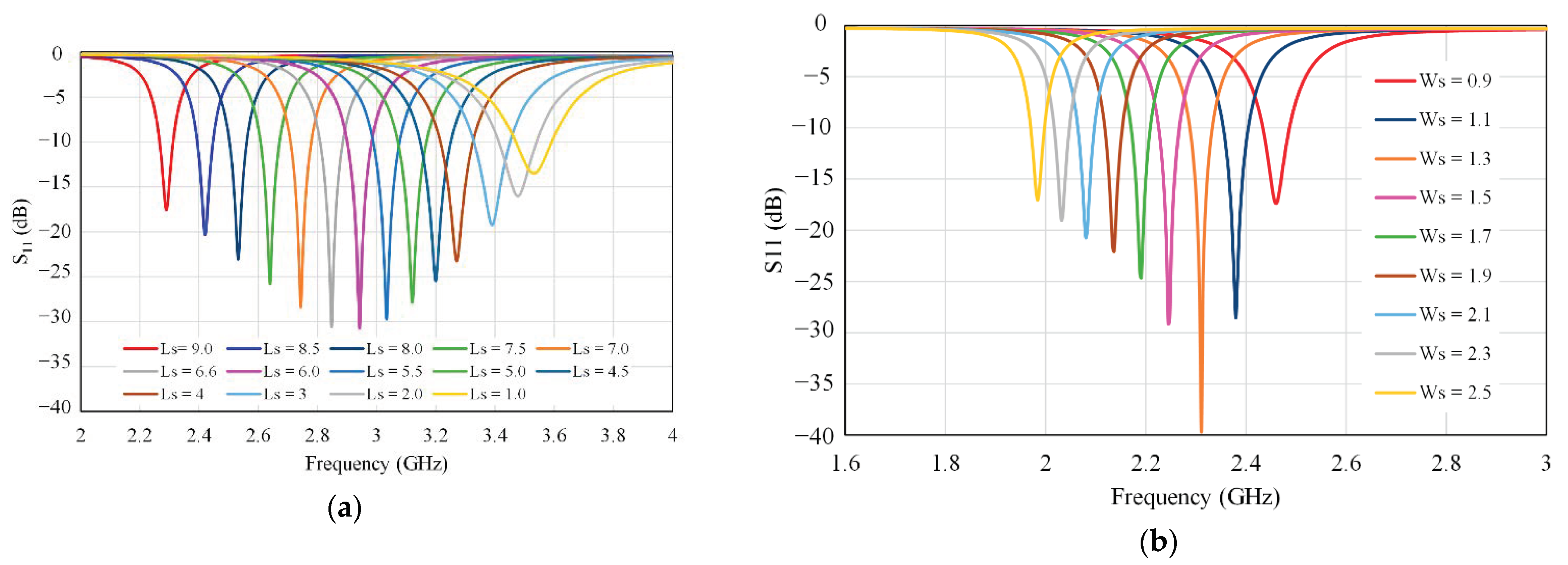
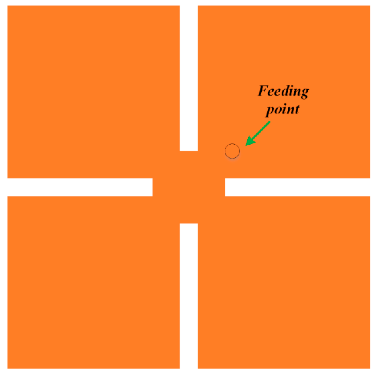
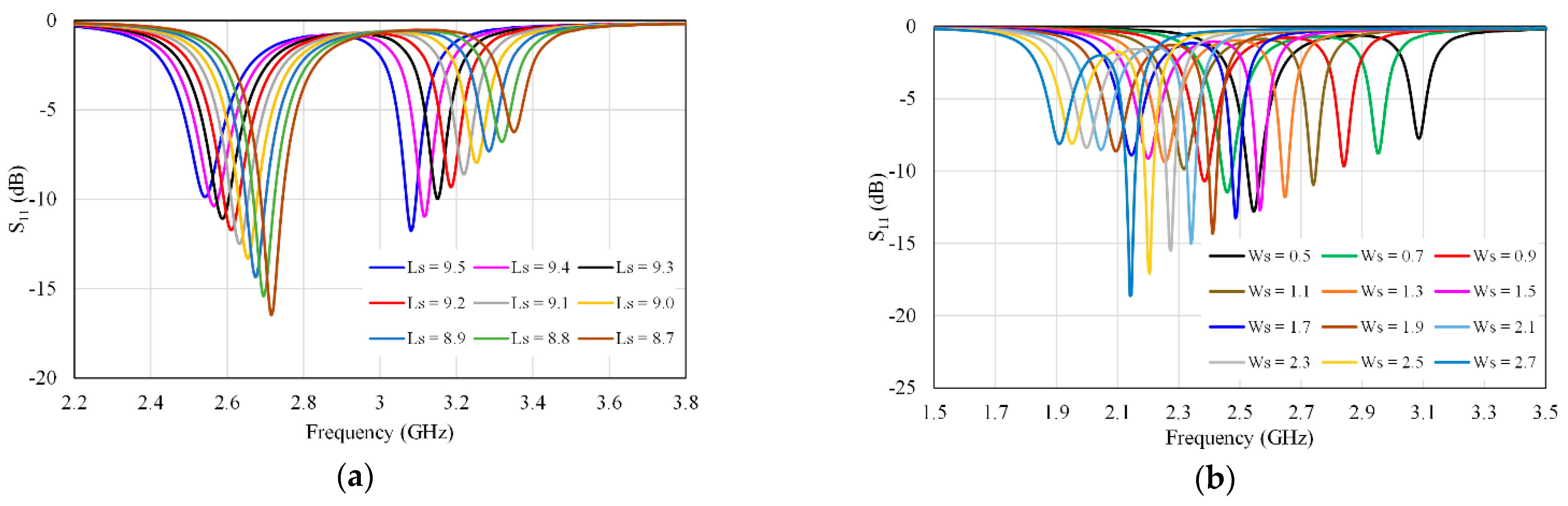
3. Slotted Square Patch
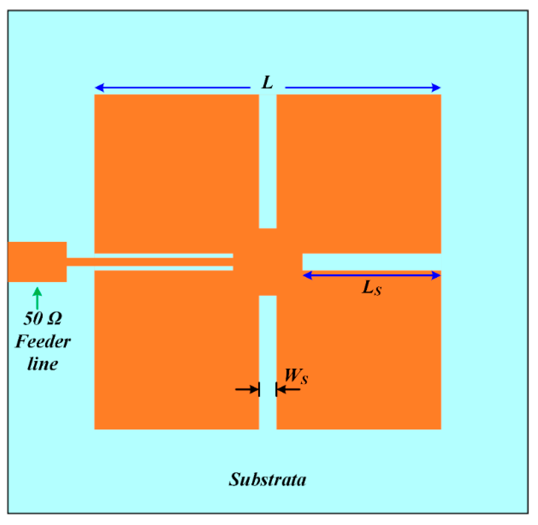
4. Single-Band Antenna Design
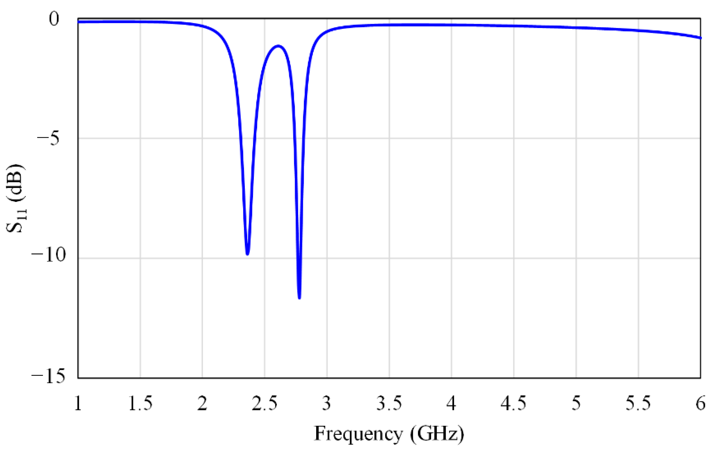
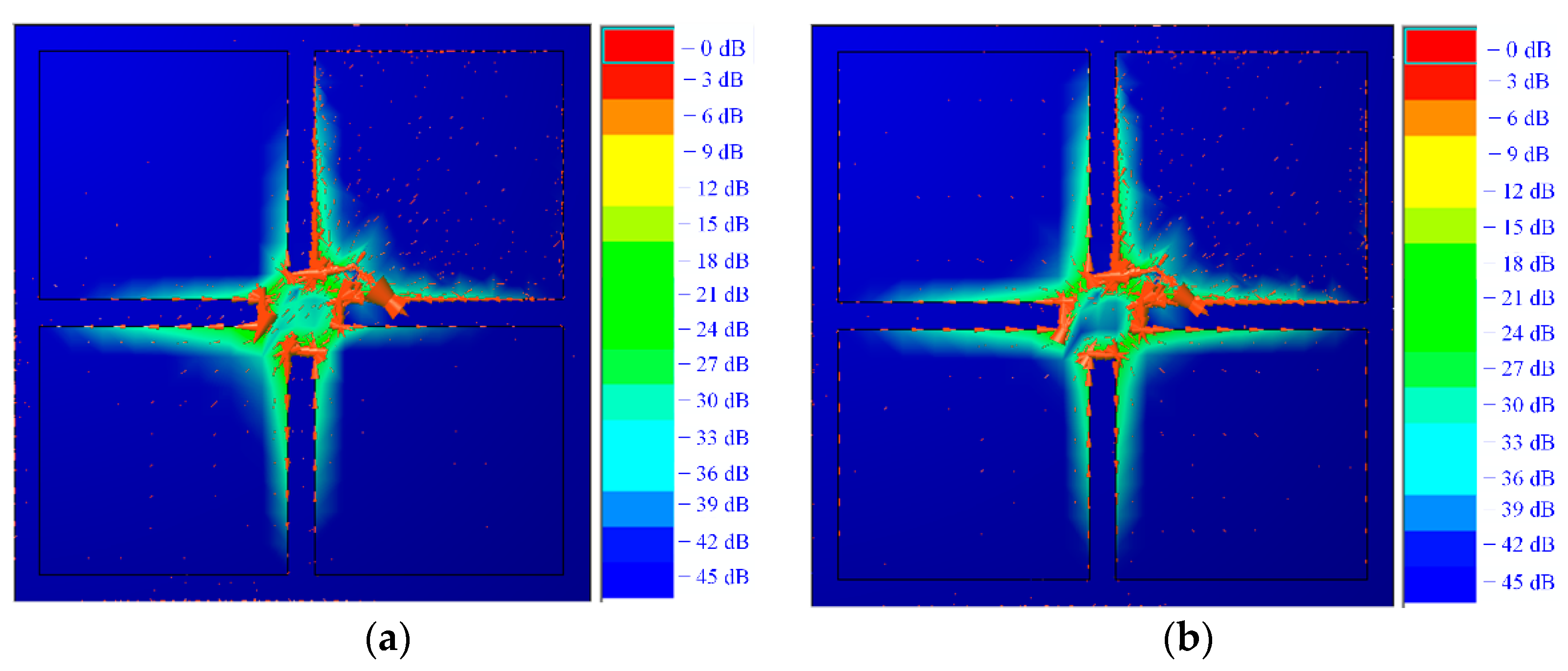
5. Dual-Band Antenna Design
6. Bandwidth Enhancement
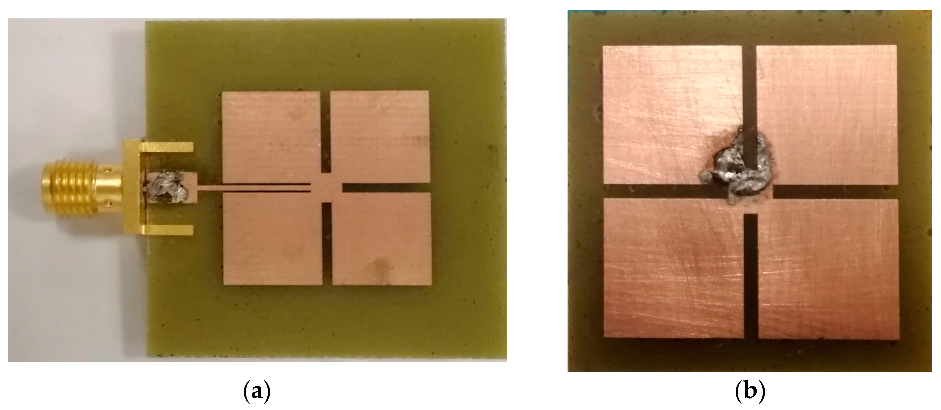
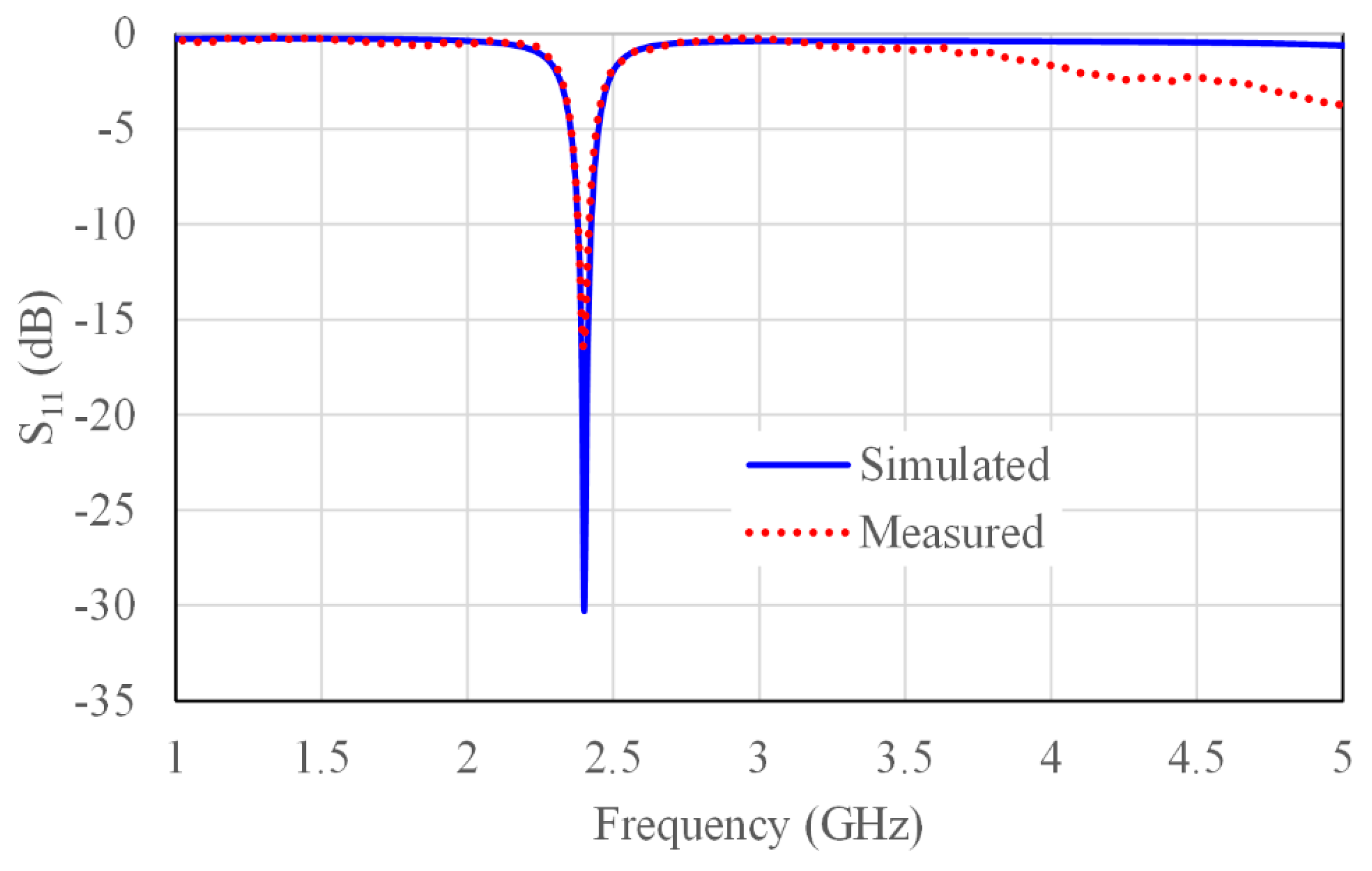
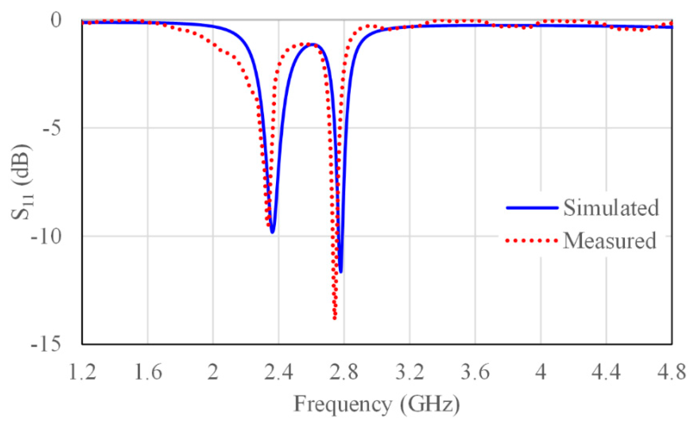
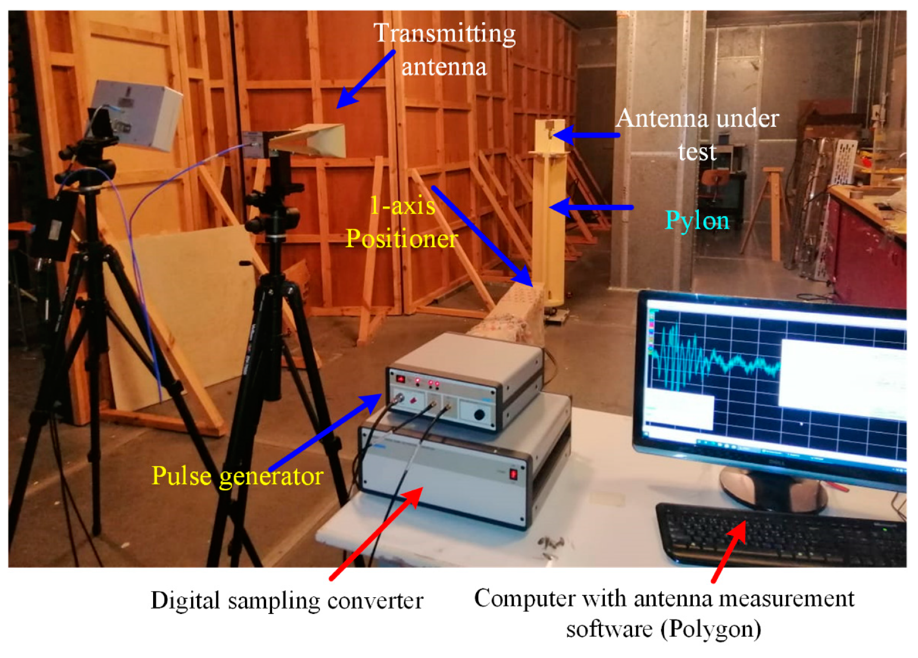
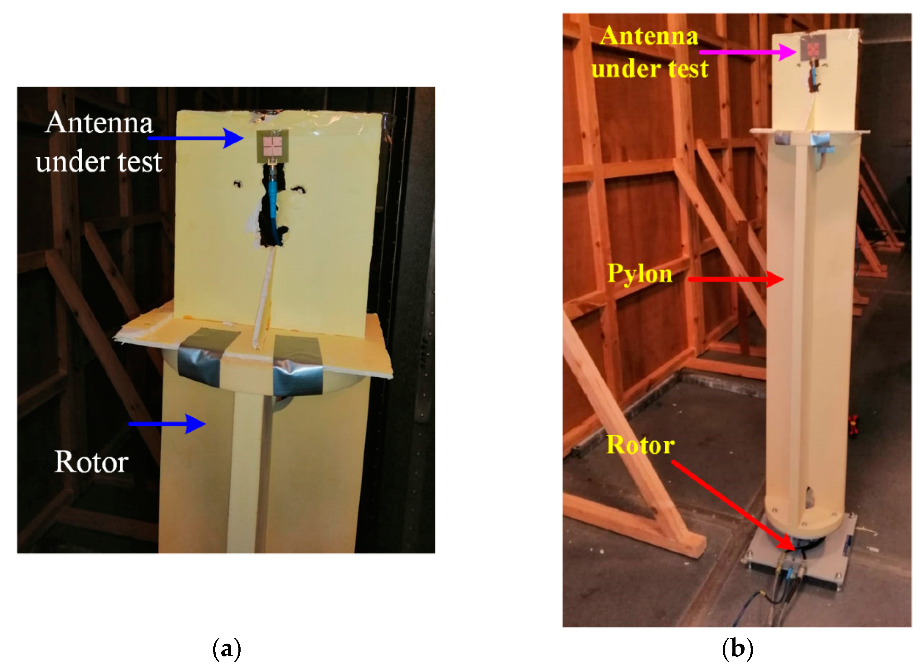
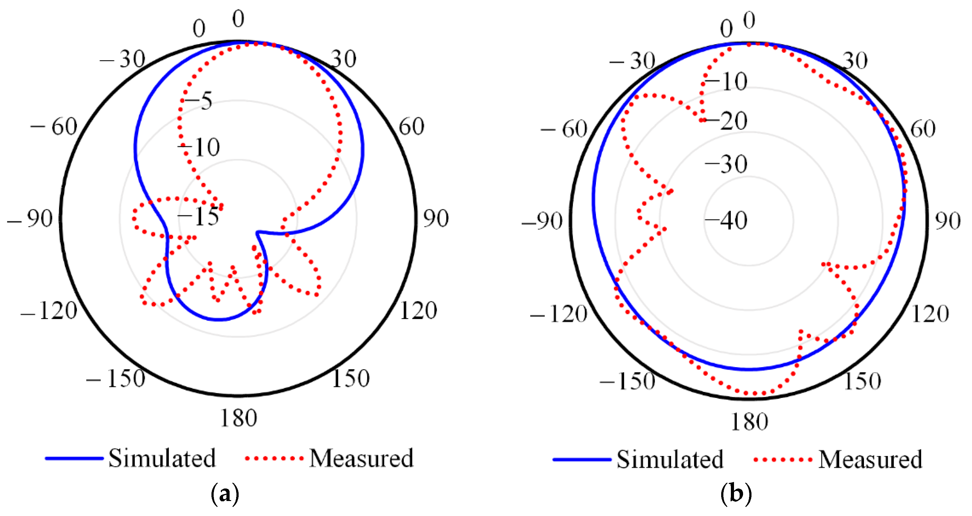
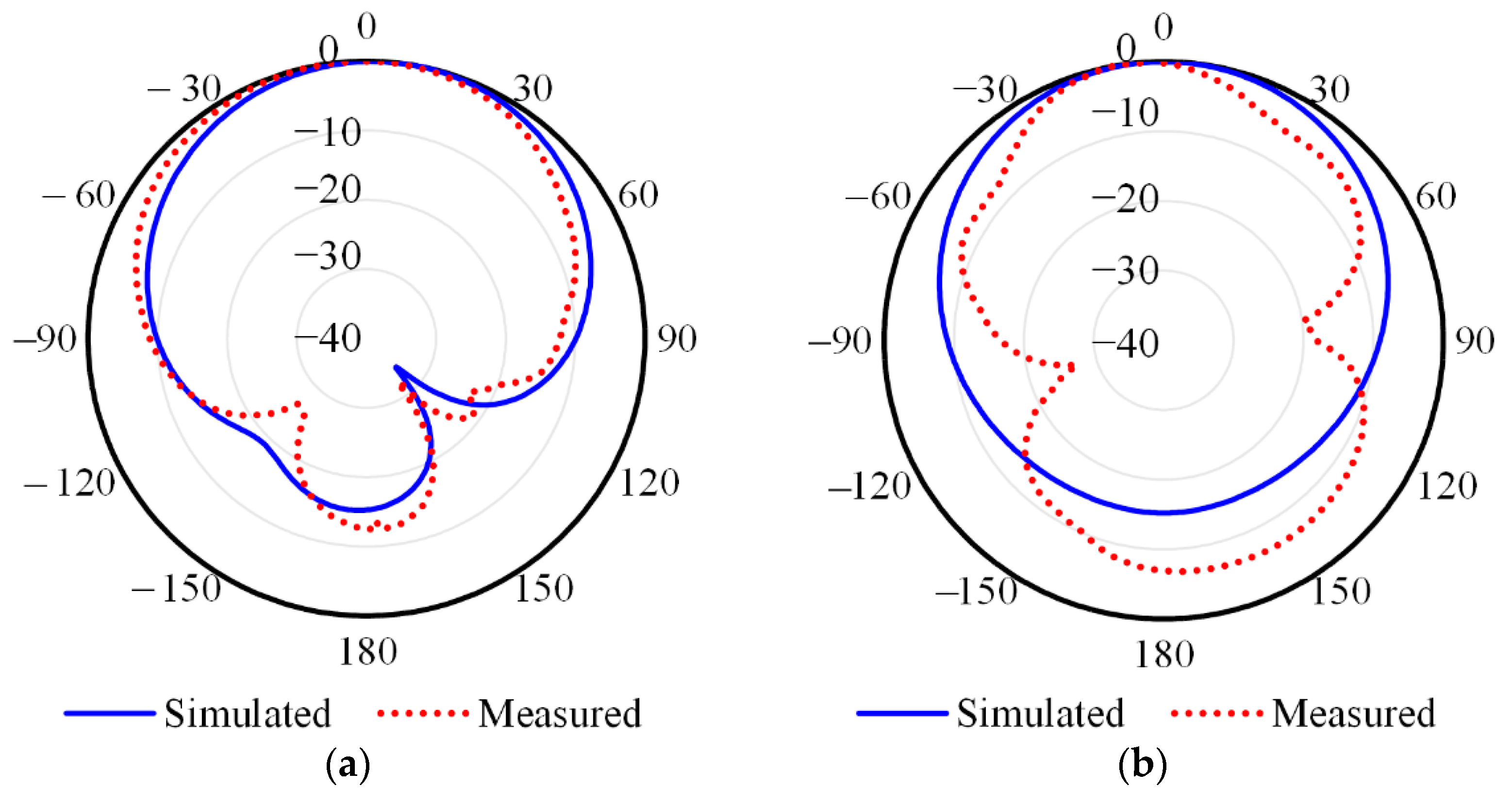
7. Experimental Results
8. Conclusions
Author Contributions
Funding
Institutional Review Board Statement
Informed Consent Statement
Data Availability Statement
Acknowledgments
Conflicts of Interest
References
- Wang, M.; Yang, L.; Shi, Y. A Dual-port Microstrip Rectenna for Wireless Energy Harvest at LTE Band. AEU Int. J. Electron. Commun. 2020, 126, 153451. [Google Scholar] [CrossRef]
- Kumar, N.; Khanna, R. A compact multi-band multi-input multi-output antenna for 4G/5G and IoT devices using theory of characteristic modes. Int. J. RF Microw. Comput. Aided Eng. 2020, 30, e22012. [Google Scholar] [CrossRef]
- Goswami, P.K.; Goswami, G. Truncated T parasite staircase fractal U-slot antenna for multiple advance internet of things applications. Microw. Opt. Technol. Lett. 2020, 62, 830–838. [Google Scholar] [CrossRef]
- Mao, Y.; Guo, S.; Chen, M. Compact dual-band monopole antenna with defected ground plane for Internet of things. IET Microw. Antennas Propag. 2018, 12, 1332–1338. [Google Scholar] [CrossRef]
- Jha, K.R.; Bukhari, B.; Singh, C.; Mishra, G.; Sharma, S.K. Compact Planar Multistandard MIMO Antenna for IoT Applications. IEEE Trans. Antennas Propag. 2018, 66, 3327–3336. [Google Scholar] [CrossRef]
- Chen, L.; Zhang, H.; Chen, Z.; Zhang, Y.; Yao, J.; Xing, Y. Design of Low-profile Dual-band Antenna for IoT Applications. In Proceedings of the 2019 3rd International Conference on Electronic Information Technology and Computer Engineering (EITCE), Xiamen, China, 18–20 October 2019; pp. 1805–1809. [Google Scholar]
- Chen, S.; Dong, D.; Liao, Z.; Cai, Q.; Liu, G. Compact wideband and dual-band antenna for TD-LTE and WLAN applications. Electron. Lett. 2014, 50, 1111–1112. [Google Scholar] [CrossRef]
- Lee, H.; Ren, D.; Choi, J.H. Dual-Band and Polarization-Flexible CRLH Substrate-Integrated Waveguide Resonant Antenna. IEEE Antennas Wirel. Propag. Lett. 2018, 17, 1469–1472. [Google Scholar] [CrossRef]
- Chung, M.-A. A miniaturized triple band monopole antenna with a coupled branch strip for bandwidth enhancement for IoT applications. Microw. Opt. Technol. Lett. 2018, 60, 2336–2342. [Google Scholar] [CrossRef]
- Abdulkawi, W.; Malik, W.; Rehman, S.; Aziz, A.; Sheta, A.; Alkanhal, M. Design of a Compact Dual-Band MIMO Antenna System with High-Diversity Gain Performance in Both Frequency Bands. Micromachines 2021, 12, 383. [Google Scholar] [CrossRef] [PubMed]
- Abdulkawi, W.M.; Sheta, A.-F.A.; Malik, W.A.; Rehman, S.U.; Alkanhal, M.S. RF MEMS Switches Enabled H-Shaped Beam Reconfigurable Antenna. Appl. Comput. Electromagn. Soc. J. 2019, 34, 1312–1319. [Google Scholar]
- Abdulkawi, W.M.; Malik, W.A.; Sheta, A.F.A.; Alkanhal, M.A. A compact dual circular patch pattern reconfigurable antenna. Microw. Opt. Technol. Lett. 2018, 60, 2762–2768. [Google Scholar] [CrossRef]
- Lee, J.N.; Kim, J.H.; Park, J.K.; Kim, J.S. Design of dual-band antenna with U-shaped open stub for WLAN/UWB applications. Microw. Opt. Technol. Lett. 2009, 51, 284–289. [Google Scholar] [CrossRef]
- Park, S.Y.; Park, J.K.; Kim, J.S. Dual-band antenna design using M-shaped open stub. Microw. Opt. Technol. Lett. 2011, 53, 455–458. [Google Scholar] [CrossRef]
- Wang, L.; Chen, J.; Ping, Y.; Han, L.; Zhang, W. Design of a Dual-band Monopole Antenna for WLAN Applications. In Proceedings of the 2019 Computing, Communications and IoT Applications (ComComAp), Shenzhen, China, 26–28 October 2019; pp. 167–169. [Google Scholar]
- Eltresy, N.; Elsheakh, D.N.; Abdallah, E.A.; Elhennawy, H.M. Multi band dual linearly polarized 2 × 2 antenna array for powering sensors in IoT systems. In Proceedings of the IEEE Global Conference on Internet of Things (GCIoT), Alexandria, Egypt, 5–7 December 2018; pp. 5–7. [Google Scholar]
- Romputtal, A.; Phongcharoenpanich, C. IoT-Linked Integrated NFC and Dual Band UHF/2.45 GHz RFID Reader Antenna Scheme. IEEE Access 2019, 7, 177832–177843. [Google Scholar] [CrossRef]
- Darimireddy, N.K.; Reddy, R.R.; Prasad, A.M. Asymmetric and symmetric modified bow-tie slotted circular patch antennas for circular polarization. ETRI J. 2018, 40, 561–569. [Google Scholar] [CrossRef]
- Chen, Y.-Y.; Jiao, Y.-C.; Zhao, G.; Zhang, F.; Liao, Z.-L.; Tian, Y. Dual-Band Dual-Sense Circularly Polarized Slot Antenna With a C-Shaped Grounded Strip. IEEE Antennas Wirel. Propag. Lett. 2011, 10, 915–918. [Google Scholar] [CrossRef]
- Wang, Z.; Zhang, G.-X.; Yin, Y.; Wu, J. Design of a Dual-Band High-Gain Antenna Array for WLAN and WiMAX Base Station. IEEE Antennas Wirel. Propag. Lett. 2014, 13, 1721–1724. [Google Scholar] [CrossRef]
- Li, Y.; Zhao, Z.; Tang, Z.; Yin, Y. Differentially Fed, Dual-Band Dual-Polarized Filtering Antenna with High Selectivity for 5G Sub-6 GHz Base Station Applications. IEEE Trans. Antennas Propag. 2020, 68, 3231–3236. [Google Scholar] [CrossRef]
- Darimireddy, N.K.; Reddy, R.R.; Prasad, A.M. Asymmetric triangular semi-elliptic Slotted Patch antennas for wireless applications. Radioengineering 2018, 27, 85. [Google Scholar] [CrossRef]
- Wang, H.; Liu, S.-F.; Zhang, L.; Li, P.; Chen, L.; Shi, X.-W. Compact wideband and dual-band antenna with directional patterns. Microw. Opt. Technol. Lett. 2015, 57, 2742–2745. [Google Scholar] [CrossRef]
- Li, L.; Zhang, X.; Yin, X.; Zhou, L. A Compact Triple-Band Printed Monopole Antenna for WLAN/WiMAX Applications. IEEE Antennas Wirel. Propag. Lett. 2016, 15, 1853–1855. [Google Scholar] [CrossRef]
- Chen, W.-S.; Yang, C.-K.; Lin, G.-Q. Compact design of printed antenna with a ground slot for USB applications. In Proceedings of the 2016 IEEE 5th Asia-Pacific Conference on Antennas and Propagation (APCAP), Kaohsiung, Taiwan, 26–29 July 2016; pp. 127–128. [Google Scholar] [CrossRef]
- Saxena, S.; Kanaujia, B.K.; Dwari, S.; Kumar, S.; Tiwari, R. A compact microstrip fed dual polarised multiband antenna for IEEE 802.11 a/b/g/n/ac/ax applications. AEU Int. J. Electron. Commun. 2017, 72, 95–103. [Google Scholar] [CrossRef]
- Tan, M.-T.; Wang, B.-Z. A Compact Dual-Band Dual-Polarized Loop-Slot Planar Antenna. IEEE Antennas Wirel. Propag. Lett. 2015, 14, 1742–1745. [Google Scholar] [CrossRef]
- Zhuo, L.; Han, H.; Shen, X.; Zhao, H. A U-shaped wide-slot dual-band broadband NB-IoT antenna with a rectangular tuning stub. In Proceedings of the 2020 IEEE 4th Information Technology, Networking, Electronic and Automation Control Conference (ITNEC), Chongqing, China, 12–14 June 2020; Volume 1, pp. 123–128. [Google Scholar]
- Sheta, A.; Dib, N.; Mohra, A. Investigation of new nondegenerate dual-mode microstrip patch filter. IEE Proc. Microw. Antennas Propag. 2006, 153, 89–95. [Google Scholar] [CrossRef]
- Alkanhal, M.; Sheta, A.F. A novel dual-band reconfigurable square-ring microstrip antenna. Prog. Electromagn. Res. 2007, 70, 337–349. [Google Scholar] [CrossRef]
- Sheta, A.F. A small size dual-mode patch filter. Int. J. Appl. Electromagn. Mech. 2008, 28, 117–122. [Google Scholar] [CrossRef]
- Sheta, A.F.; Al-Eshaikh, M.A. A New Small Size Non-degenerate Dual-mode Patch Filter. J. Electromagn. Waves Appl. 2011, 25, 1504–1514. [Google Scholar] [CrossRef]
- Al-Yasir, Y.I.A.; Alkhafaji, M.K.; Alhamadani, H.A.; Parchin, N.O.; Elfergani, I.; Saleh, A.L.; Rodriguez, J.; Abd-Alhameed, R.A. A New and Compact Wide-Band Microstrip Filter-Antenna Design for 2.4 GHz ISM Band and 4G Applications. Electronics 2020, 9, 1084. [Google Scholar] [CrossRef]
- Islam, M.S.; Ullah, A.; Beng, G.K.; Amin, N.; Misran, N. A Modified Meander Line Microstrip Patch Antenna with Enhanced Bandwidth for 2.4 GHz ISM-Band Internet of Things (IoT) Applications. IEEE Access 2019, 7, 127850–127861. [Google Scholar] [CrossRef]
- Saghati, A.P.; Azarmanesh, M.; Zaker, R. A Novel Switchable Single- and Multifrequency Triple-Slot Antenna for 2.4-GHz Bluetooth, 3.5-GHz WiMax, and 5.8-GHz WLAN. IEEE Antennas Wirel. Propag. Lett. 2010, 9, 534–537. [Google Scholar] [CrossRef]
- Kulkarni, J. Multi-band printed monopole antenna conforming bandwidth requirement of GSM/WLAN/WiMAX standards. Prog. Electromagn. Res. Lett. 2020, 91, 59–66. [Google Scholar] [CrossRef]
- Mansour, R. Design of superconductive multiplexers using single-mode and dual-mode filters. IEEE Trans. Microw. Theory Tech. 1994, 42, 1411–1418. [Google Scholar] [CrossRef]
- Du, Z.; Gong, K.; Fu, J.; Gao, B. Analysis of microstrip fractal patch antenna for multi-band communication [by FDTD]. Electron. Lett. 2001, 37, 805–806. [Google Scholar] [CrossRef]
- Elrashidi, A.; Elleithy, K.; Bajwa, H. Performance Analysis of a Microstrip Printed Antenna Conformed on Cylindrical Body at Resonance Frequency 4.6GHz for TM01 Mode. Procedia Comput. Sci. 2012, 10, 775–784. [Google Scholar] [CrossRef]
- Liu, N.-W.; Zhu, L.; Choi, W.-W.; Zhang, J.-D. A Novel Differential-Fed Patch Antenna on Stepped-Impedance Resonator with Enhanced Bandwidth under Dual-Resonance. IEEE Trans. Antennas Propag. 2016, 64, 4618–4625. [Google Scholar] [CrossRef]
- Liu, N.-W.; Zhu, L.; Choi, W.-W. A Differential-Fed Microstrip Patch Antenna with Bandwidth Enhancement under Operation of TM10and TM30Modes. IEEE Trans. Antennas Propag. 2017, 65, 1607–1614. [Google Scholar] [CrossRef]
- Wang, J.; Liu, Q.; Zhu, L. Bandwidth Enhancement of a Differential-Fed Equilateral Triangular Patch Antenna via Loading of Shorting Posts. IEEE Trans. Antennas Propag. 2016, 65, 36–43. [Google Scholar] [CrossRef]
- Parizi, S.A.R. Bandwidth Enhancement Techniques. In Trends in Research on Microstrip Antennas; IntechOpen: London, UK, 2017; Volume 1. [Google Scholar]
- Kumar, A.; Gupta, N.; Gautam, P.C. Gain and Bandwidth Enhancement Techniques in Microstrip Patch Antennas—A Review. Int. J. Comput. Appl. 2016, 148, 9–14. [Google Scholar] [CrossRef]
- Elsagheer, R.M. Study on bandwidth enhancement techniques of microstrip antenna. J. Electr. Syst. Inf. Technol. 2016, 3, 527–531. [Google Scholar] [CrossRef][Green Version]
- Waterhouse, R. Microstrip Patch Antennas: A Designer’s Guide; Springer Science & Business Media: New York, NY, USA, 2003. [Google Scholar]
- Kumar, G.; Ray, K.P. Broadband Microstrip Antennas; Artech House: London, UK, 2003. [Google Scholar]
- Kushwaha, R.K.; Karuppanan, P. Proximity-coupled high gain graphene patch antenna using holey dielectric superstrate for terahertz applications. Optik 2021, 240, 166793. [Google Scholar] [CrossRef]
- Swetha, R.; Anjaneyulu, L. Novel Design and Characterization of Wide Band Hook Shaped Aperture Coupled Circularly Polarized Antenna for 5G Application. Prog. Electromagn. Res. C 2021, 113, 161–175. [Google Scholar] [CrossRef]
- Rosado-Sanz, J.; Jarabo-Amores, M.; Mata-Moya, D.; Gómez-Del-Hoyo, P.; Del-Rey-Maestre, N. Broadband modified-circle-shape patch antenna with H-aperture feeding for a passive radar array. Aerosp. Sci. Technol. 2021, 110, 106445. [Google Scholar] [CrossRef]
- Sun, J.; Luk, K.-M. A Circularly Polarized Water Patch Antenna. IEEE Antennas Wirel. Propag. Lett. 2020, 19, 926–929. [Google Scholar] [CrossRef]
- Lin, W.; Wong, H. Wideband Circular-Polarization Reconfigurable Antenna with L-Shaped Feeding Probes. IEEE Antennas Wirel. Propag. Lett. 2017, 16, 2114–2117. [Google Scholar] [CrossRef]
- Sumithra, P.; Kannadassan, D. Bandwidth Enhancement of Low-Profile Slot Antennas using Theory of Characteristic Modes. AEU Int. J. Electron. Commun. 2021, 138, 153868. [Google Scholar] [CrossRef]
- Moussa, K.; Amar, A.; Mabrouk, M.; Mohamed, H. Slotted E-Shaped Meta-Material Decoupling Slab for Densely Packed MIMO Antenna Arrays. Micromachines 2021, 12, 873. [Google Scholar] [CrossRef]
- Mistry, K.K.; Lazaridis, P.I.; Zaharis, Z.D.; Loh, T.H. Design and Optimization of Compact Printed Log-Periodic Dipole Array Antennas with Extended Low-Frequency Response. Electronics 2021, 10, 2044. [Google Scholar] [CrossRef]
- Gatti, R.V.; Rossi, R.; Dionigi, M. Single-Layer Line-Fed Broadband Microstrip Patch Antenna on Thin Substrates. Electronics 2020, 10, 37. [Google Scholar] [CrossRef]
- Tran, H.H.; Bui, C.D.; Nguyen-Trong, N.; Nguyen, T.K. A Wideband Non-Uniform Metasurface-Based Circularly Polarized Reconfigurable Antenna. IEEE Access 2021, 9, 42325–42332. [Google Scholar] [CrossRef]
- Elahi, M.; Trinh-Van, S.; Yang, Y.; Lee, K.-Y.; Hwang, K.-C. Compact and High Gain 4 × 4 Circularly Polarized Microstrip Patch Antenna Array for Next Generation Small Satellite. Appl. Sci. 2021, 11, 8869. [Google Scholar] [CrossRef]
- Wang, J.; Cui, W.; Zhou, Y.; Liu, R.; Wang, M.; Fan, C.; Zheng, H.; Li, E. Design of Wideband Antenna Array with Dielectric Lens and Defected Ground Structure. Electronics 2021, 10, 2066. [Google Scholar] [CrossRef]
- Peng, H.; Zhi, R.; Yang, Q.; Cai, J.; Wan, Y.; Liu, G. Design of a MIMO Antenna with High Gain and Enhanced Isolation for WLAN Applications. Electronics 2021, 10, 1659. [Google Scholar] [CrossRef]
- Geozandas. Time-Domain Antenna Measurement Systems. Available online: https://geozondas.com/main_page.php?pusl=12 (accessed on 10 October 2021).


| Ref. | Antenna Type | Substrate | No. of Ports | Resonance Frequencies (GHz) | Dimensions (mm2) | Maximum Gain (dB) | Bandwidth (MHz) |
|---|---|---|---|---|---|---|---|
| [1] | Slotted patch | FR-4 | 2 | 1.73 and 2.53 | 48 × 48 | −3.8 and 1.9 | 30 |
| [4] | U-shaped | Rogers RO4003 | 1 | 3.5 | 14 × 14 | 1.42 | 200 |
| [5] | Slotted patch | FR-4 | 5 | 0.9, 1, 1.72, 2.18, 5 and 5.5 | 120 × 65 | 0.53, −0.96, 1.97, 3.75, 2.46, and 4.9 | 150 |
| [6] | PIFA | FR-4 | 1 | 1.8 and 2.4 | 45 × 32 | 1.6 and 1.8 | 50 |
| [11] | H-shaped | Rogers RT5880 | 1 | 1.8 | 72 × 17 | 5.5 | 40 |
| [12] | Slotted circular patch | FR-4 | 1 | 1.8 | 24 × 40 | 1.9 | 180 |
| [34] | Meander line | FR-4 | 1 | 2.4 | 40 × 10 | 1.35 | 146 |
| [35] | Slotted | FR-4 | 1 | 2.4, 3.5, and 5.8 | 80 × 80 | 2.33, 3.14, and 2.89 | 140 |
| [36] | C-shaped | FR-4 | 1 | 1.8, 2.4, and 5 | 209 × 260 | 4.40, 4.75, and 5.25 | 100 |
| [15] | Monopole | FR-4 | 1 | 2.4 and 5 | 34 × 26 | 2.2 and 2 | 220 |
| This work | Slotted square | Rogers RT5880 | 1 | 2.4 | 41.5 × 38.5 | 3.39 | 18 |
| 2.4 and 2.8 | 38.5 × 38.5 | 3.45 and 3.2 | 20 | ||||
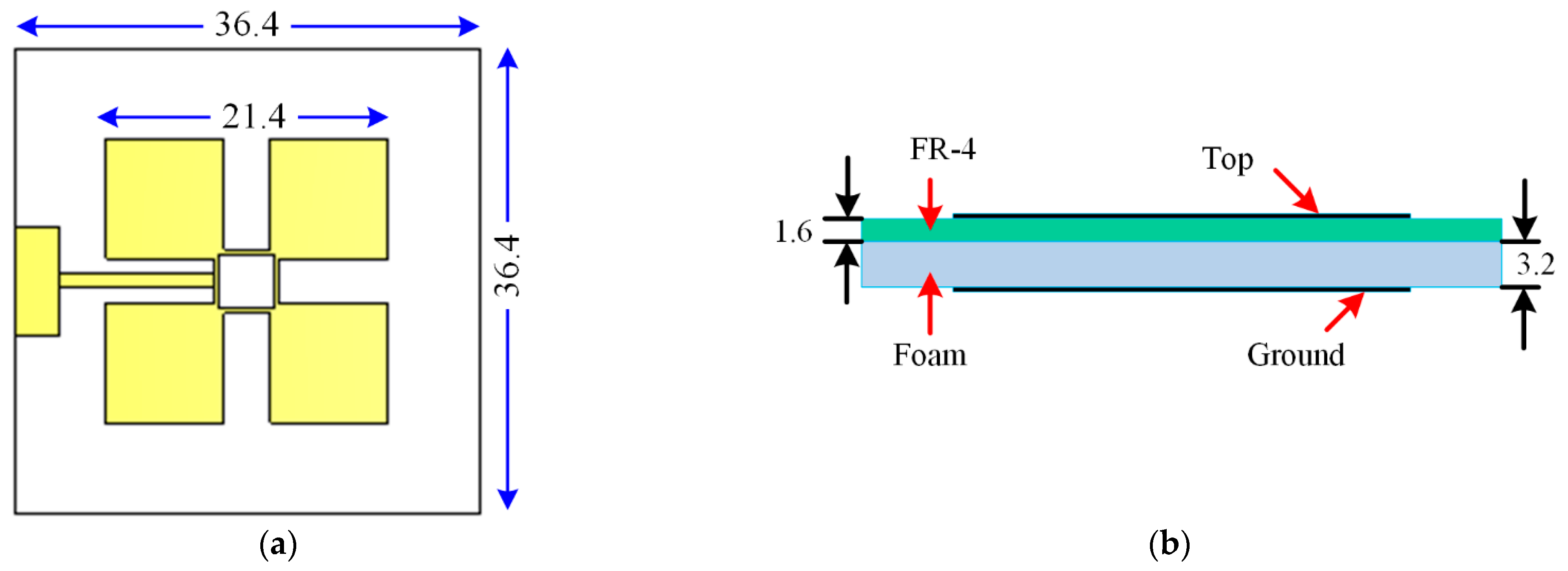
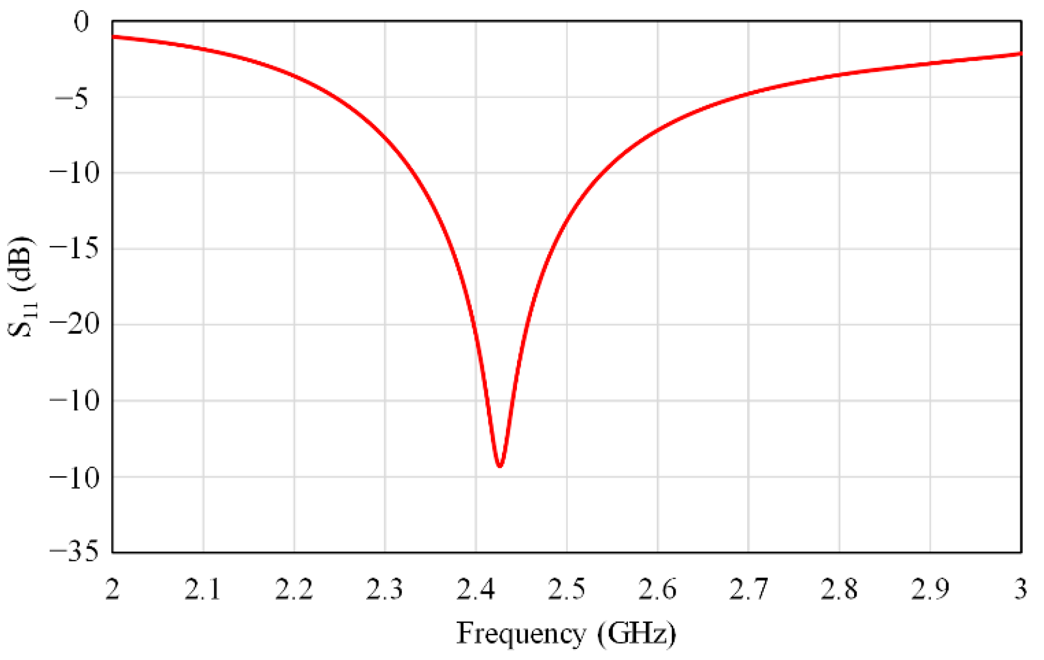
| Wideband slotted square | FR-4 | 2.4 | 36.4 × 36.4 | 2.45 | 220 |
Publisher’s Note: MDPI stays neutral with regard to jurisdictional claims in published maps and institutional affiliations. |
© 2021 by the authors. Licensee MDPI, Basel, Switzerland. This article is an open access article distributed under the terms and conditions of the Creative Commons Attribution (CC BY) license (https://creativecommons.org/licenses/by/4.0/).
Share and Cite
Abdulkawi, W.M.; Sheta, A.F.A.; Elshafiey, I.; Alkanhal, M.A. Design of Low-Profile Single- and Dual-Band Antennas for IoT Applications. Electronics 2021, 10, 2766. https://doi.org/10.3390/electronics10222766
Abdulkawi WM, Sheta AFA, Elshafiey I, Alkanhal MA. Design of Low-Profile Single- and Dual-Band Antennas for IoT Applications. Electronics. 2021; 10(22):2766. https://doi.org/10.3390/electronics10222766
Chicago/Turabian StyleAbdulkawi, Wazie M., Abdel Fattah A. Sheta, Ibrahim Elshafiey, and Majeed A. Alkanhal. 2021. "Design of Low-Profile Single- and Dual-Band Antennas for IoT Applications" Electronics 10, no. 22: 2766. https://doi.org/10.3390/electronics10222766
APA StyleAbdulkawi, W. M., Sheta, A. F. A., Elshafiey, I., & Alkanhal, M. A. (2021). Design of Low-Profile Single- and Dual-Band Antennas for IoT Applications. Electronics, 10(22), 2766. https://doi.org/10.3390/electronics10222766