Article

Experimental Application of Bluetooth Low Energy Connectionless in Smart Cities

by
Juan Carlos García-Ortiz
1,
Javier Silvestre-Blanes
2,* and
Víctor Sempere-Payá
3
1
Instituto Tecnológico de Informática (ITI), 46022 Valencia, Spain
2
Departamento de Informática de Sistemas y Computadores (DISCA), Instituto Tecnológico de Informática (ITI), Escuela Politécnica Superior de Alcoy (EPSA), Universitat Politècnica de València (UPV), 03801 Alcoy, Spain
3
Departamento de Comunicaciones (DCOM), Instituto Tecnológico de Informática (ITI), Universitat Politècnica de València (UPV), 46022 Valencia, Spain
*
Author to whom correspondence should be addressed.
Electronics 2021, 10(22), 2735; https://doi.org/10.3390/electronics10222735
Submission received: 6 October 2021 / Revised: 3 November 2021 / Accepted: 8 November 2021 / Published: 10 November 2021
(This article belongs to the Section Microwave and Wireless Communications)

Abstract

:
Communication networks are a key element in the development of Smart Cities. This field is a constantly evolving environment, for which new protocols are constantly appearing. Due to the heterogeneous nature of the technologies, the most appropriate candidate must be selected in order to get the best performance to satisfy the application requirements. One of these protocols is Bluetooth Low Energy (BLE), particularly with the upgrades introduced in version 5.x. Its new features are focused on providing increased range, improving robustness, and expanding beaconing capabilities. Connectionless applications such as information broadcasting in Smart Cities could take advantage of this protocol. Furthermore, the wide availability on common devices (mobile phones, car infotainment, etc.), the deployment of these applications can be carried out easily and at low cost. This paper presents an experimental evaluation of the new robust, long-range radio mode of BLE over a set of Smart Cities scenarios, taking into account different conditions such as wireless interference, distances, dynamicity, etc. The results show a promising performance of the protocol even with these constraints.

1. Introduction

There is currently a great deal of interest in the development and implementation of infrastructures and applications for Smart Cities. A Smart City is a complex system, whose ultimate goal is to make cities more attractive and sustainable, which is supported by an intensive use of ICTs (Information and Communication Technology), providing various digital services that help to achieve these objectives. Therefore, heterogeneous technologies must be combined, even when some of them have not been sufficiently proven. The work presented in [1] highlights how the IoT (Internet of Things) is still in an evolutionary phase and must still face many challenges, including interoperability between agents and devices (due to heterogeneity), economic aspects, problems related to mobility and dynamism (mobility-related problem), and the standardization of solutions and technologies. These needs are also analysed in [2], where the standards are reviewed (there are more than 1800 related standards) with the different definitions of the Smart City concept, including data and use cases, and the differences and similarities between different international organizations. The need for new technologies for this environment is highlighted, and there is a particular need for more robust ICT infrastructures. There is also talk of digital exclusion from society, i.e., users who are difficult to reach, either because of social exclusion or because they are too young or too old (although Bluetooth technology can be an advantage in this respect, as it is integrated in many common devices such as cell phones or tablets). In [3], a bibliometric study on IoT research and applications in Smart Cities is carried out, identifying seven fundamental lines of research. One of these lines is mobile connectivity, although these authors consider it to be basically focused on 5G technologies.
In [4], the potential of BLE (Bluetooth Low Energy) in the field of Smart Cities, mainly for proximity-based services, is analysed, highlighting the security problems that BLE suffers from. In [5], the use of BLE in Smart City applications is justified, extending the concept and use of PAN (Personal Area Network) to cities. This requires direct interaction between users and objects. These Smart objects can be considered to be CPS (Cyber Physical Systems) because of the ability to handle a physical interface of specific city equipment added to a limited computational capacity to communicate with a specific set of protocols. Other applications of BLE in Smart Cities are in the field of energy [6], healthcare [7], smart carparks [8], alert systems [9], vehicle-pedestrian collision warning systems [10] and location/positioning of pedestrians [11]. In [
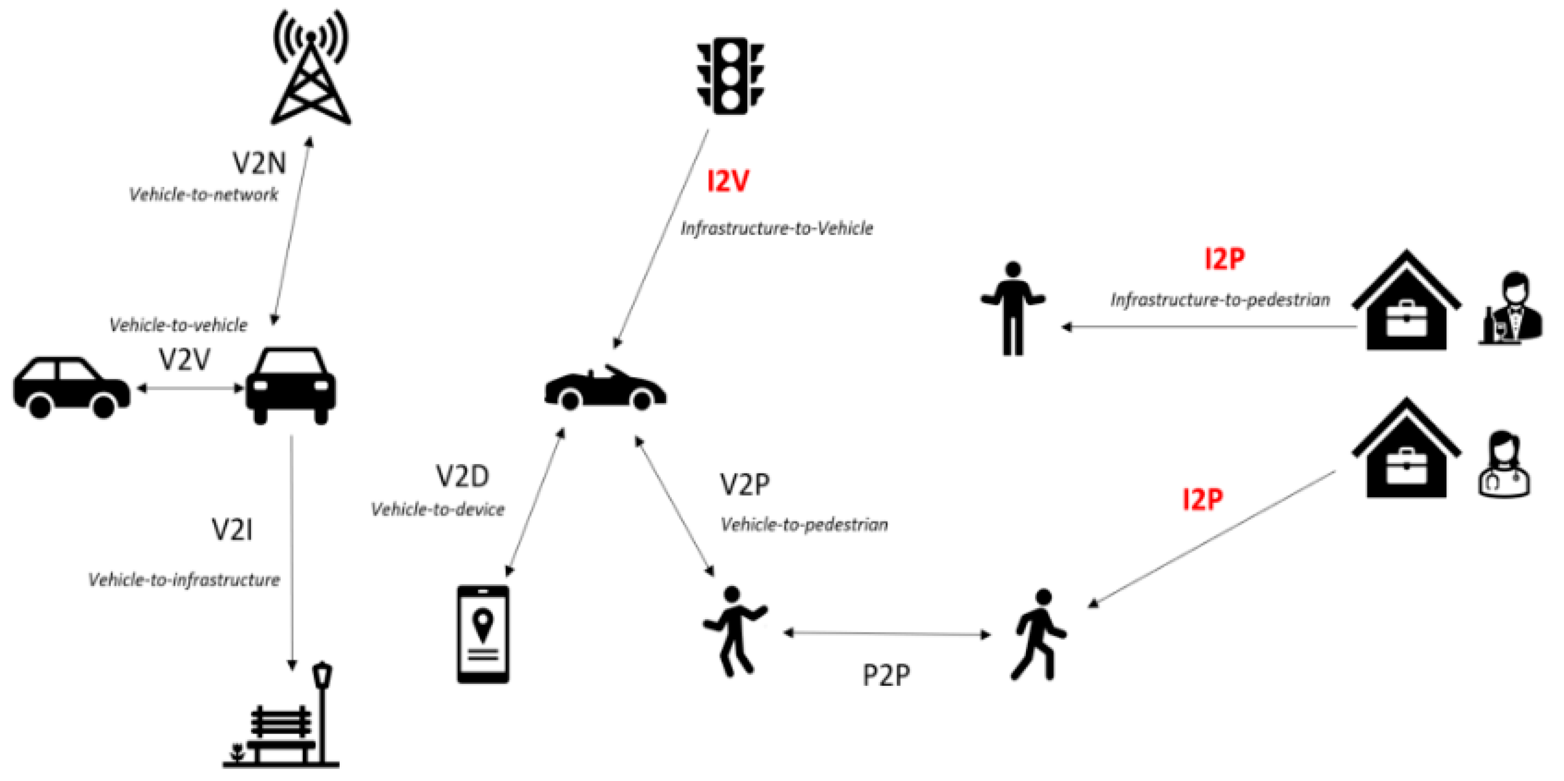
12], the use of BLE in I2V (Infrastructure to Vehicle) applications is analysed (and extended in this work). V2X (Vehicle to Everything) applications are one of the most promising technologies in the field of ITS (Intelligent Transport Systems) and can be considered as another element of Smart Cities. It is considered that V2X applications can be classified into the following categories [13]: infotainment; traffic efficiency; traffic safety; cooperative driving. Among these categories, traffic efficiency applications are aimed at improving the flow of road traffic, such as intersection coordination or congestion management. An example of the types of communication in these environments is shown in Figure 1.
While some of these applications may require low latency communications, others have less demanding requirements [14], and they can be classified as non-safety applications such as congestion warning, service finder, TLVC (Traffic-Light-To-Vehicle Communication), or CACC (Cooperative Adaptive Cruise Control)—exactly the kind of applications on which this work is focused. Thus, BLE can be an alternative in I2V-V2I-I2P (Infrastructure Vehicle-Vehicle to Infrastructure-Infrastructure to Pedestrian) environments and other Smart City applications compared to other more complex, and expensive, solutions. In fact, one of the biggest advantages offered by BLE is that it does not require previous infrastructure, as well as having a strong market penetration and wide availability. BLE is commonly used in electronics and vehicle devices, which makes this technology an ideal candidate for use in I2V applications, with respect to other new technologies, such as DSRC (Dedicated Short-Range Communications) [15,16], in which no infrastructure is needed to support these non-safety applications. Another possible use of BLE is its application in Inter-vehicular Communications. In [17], its robustness in different scenarios, such as a V2V system, is analysed but only focuses on BLE 4.x version not using the new protocol updates, limiting the potential range of applications. In [13], different access technologies for this type of environment are analysed, highlighting classic Bluetooth as a viable technology for intra-vehicle infotainment system applications but systematically discarding it for other areas, considering an operating range (personal operating space) of 10 m for this version of the protocol and the difficulties in establishing connections with respect to other vehicles (vehicles approaching). However, unlike classic Bluetooth, the emergence of BLE, offering much wider communication range and the possibility of implementing information broadcasting applications (where it is not necessary to complete the process of establishing a connection pair), enables this technology in these types of applications [15,16]. From this point of view, the use of BLE as an I2V communication network has been analysed in different scenarios, using its 4.0 version but in a connection-based communication mode [18]. The work in [19] compares BLE 4.0 and Zigbee for this type of application, indicating the greater stability and robustness of Zigbee but highlighting that it is a much less widespread technology with a much shorter range and speed than BLE [20]. Nevertheless, these studies are focused on BLE connected mode and are not applicable for non-safety applications or I2V and I2P applications. An additional review of alternative V2X communications technologies can be found in [16], highlighting WiFi Halow, LTE-M, NB-IoT, and BLE 5.x as potential candidates. In [21], the problems of coexistence of Bluetooth and 802.11 are analysed, limiting the range to 50 m, but using classic Bluetooth 2.0 and a power of only 4 dBm, which does not take advantage of the new features and performance of BLE. In [22], distances of up to 527 m are achieved while maintaining connections, although this work also highlights the interference that can be caused by conventional elements in cities, such as trees, which can limit the distance to below 100 m. Finally, although the networks that will support ITS technologies are still subject to study, development, and testing [23], the analysis and tests carried out in this work are in agreement with the authors of [16]. They indicate that BLE is a technology with huge potential to significantly improve safety conditions in the Smart Cities and roads of the future [24] (“Smart flexible ubiquitous hybrid vehicle networks based on IoT and 5G communication, which are able to use any type of available communication, is a promising concept to significantly improve road safety in the future”).
The aim of this work is to analyse the use of BLE over these kinds of environments and, in particular, over connectionless applications for information transmission. The maturity and low cost of the technology could enable fast, easy deployment in comparison to other solutions. Due to the availability of the technology on mobile phones, laptops, car infotainment devices, etc., with no additional modifications, new I2V and Smart Cities applications could benefit from its use.

2. BLE (Bluetooth Low Energy)

The Bluetooth protocol [25] is one of the most popular protocols for wireless personal area communication (PAN). With its technological evolution over recent years, the protocol has been improved in successive versions to support new features, such as security, robustness, transmission speed, and other additional functionalities, in order to adapt to the new applications. However, with the emergence of sensor networks and/or the need to interconnect resource-constrained devices (mobile devices, smart watches, sensors, etc.) in which energy consumption must be optimized, the Bluetooth protocol has lost popularity due to the emergence of other protocols more suitable for these requirements, such as Zigbee or ANT. For this reason, the Bluetooth Special Interest Group (SIG) presented the Bluetooth Low Energy protocol (BLE). This is a new low energy protocol (not compatible with classic or standard Bluetooth) especially suitable for environments with restrictions in terms of energy consumption and sensor network applications such as Smart Cities, vehicular communications, beaconing, indoor location, etc.
BLE is not compatible with the classic version (although it can coexist with it), and so, it was renamed Bluetooth Smart only for devices that integrate the BLE part, or Bluetooth Smart Ready, and to those that were able to work with both the classic protocol and BLE. This led to confusion among manufacturers and users, so the revision of the Bluetooth 4.0 protocol was presented, which integrates both protocols together, subdividing it into two components (classic Bluetooth and Bluetooth Low Energy).
BLE operates in the 2.4 Ghz ISM (Industrial Scientific Medical) band, using a Frequency-Hopping-Spread-Spectrum algorithm to provide robustness and reliability in communications, making a division into 40 channels that are classified into two types, as shown in Figure 2:
  • Primary channels: used for sending and broadcasting notifications and initiating the device discovery/scanning process. There are three channels (37, 38, and 39) located in different non-adjacent segments of the band in order to minimize potential interference with the WiFi protocol (with which it shares the same frequency range) and to guarantee at least one primary channel with good signal quality.
  • Secondary channels: these are used for the transfer of information between the connected devices and cover the remaining channels from 0 to 36. This set of channels is used by the Frequency Hopping algorithm.
The BLE device-to-device communication model defines two states [24]:
  • Connected: in which some devices act as peripheral devices (peripheral) and others as central devices (central). In this case, the peripheral devices have a server-like role and are usually characterized as sensors, in which a central device makes data requests. This model is suitable when there is a need for interaction and control among the members of the network and is based on a model defined by profiles, services and characteristics.
  • Offline: in which there are transmitting devices (advertisers) and others that remain listening for messages (scanners). In this case, the notifiers transmit beacons with concrete information that can be captured by the listening devices. This model is suitable for notification of short warning/beacon/advertising messages or in highly dynamic scenarios with node input/output over time.
The success of BLE has led to the incorporation of improvements, which have brought revisions to the standard, and the release of a new version. Thus, in 2017, the release of Bluetooth 5.0 was announced, adding substantial improvements in the BLE part, aimed at improving the robustness and reliability of communications, a greater signal range, and a higher data transmission capacity for advertisements, as shown in (Table 1).
In order to increase the range and reliability of communications, new configuration options for the physical layer have been added to the basic transmission mode, called LE_1M, which allows speeds of up to 1 Mb/s. Thus, there are now two additional modes, called LE_2M and LE_CODED, as shown in (Table 2). The first one allows the transmission speed to be increased up to a maximum of 2 Mb/s, focused on increasing the throughput in connection-oriented communications at the cost of losing some coverage.
On the other hand, in order to increase reliability and maximum communication range (at the cost of losing transmission speed), the LE_CODED mode is introduced. This is based on the transmission of a greater number of symbols for each bit, making it possible to implement an algorithm for error correction at the destination known as FEC (Forward Error Correction) in addition to CRC (Cyclic Redundancy Check), allowing the information to be recovered in the event of minor interference during transmission. It can be configured in the number of symbols to be transmitted to obtain the best balance between speed and robustness: S = 2 for higher speed or S = 8 for higher resilience against errors.
Additionally, improvements have been introduced in the packets that are used for beacon notification (advertisements) in connection-less applications. Advertisements are transmitted by devices on primary channels. When such a message is to be sent, it is released periodically on channels 37, 38, and 39 consecutively. This is called the advertisement interval and establishes the frequency and repetition of sending the message on the three primary channels. The nodes listening for messages remain monitoring a primary channel for a period of time known as scan interval, passing after the completion of this period to monitor the next primary channel in sequence and repeating this process indefinitely. This ensures that there is always a time segment listening to each primary channel, and beacons can be received. In addition, in order to reduce the power consumption associated with a high active radio time, it is possible to define the scan window that represents the effective listening time during an interval scan, as shown in the image (Figure 3).
The packets, or PDUs (Packet Data Units), transmitted over the primary channels have a theoretical maximum payload size of 31 bytes in the base version of BLE 4.x. However, this size is significantly reduced by the introduction of different fields, descriptors, and information at the different levels of the protocol stack, in some cases leaving only a small number of bytes free: around 10 bytes for application level data (in a non-optimized standard use). This could be a major limitation for the notification of more extensive information. The revised BLE 5.x introduces several improvements aimed at substantially increasing the payload size. For this purpose, messages are divided into packets: a pointer sent in primary channels and the message content transmitted in secondary channels. The pointer has the number of secondary channels carrying the data. In this way, it is possible to surpass the limitation of the theoretical maximum message size of 31 bytes to the theoretical maximum allowed 255 bytes of a packet from a secondary channel, as can be seen in Figure 4. However, it should be noted that, with BLE 4.x, the same payload is transmitted three times on the three different channels, while in BLE 5.x, it is transmitted only once on the secondary channel. This also has its drawbacks, although the introduction of the LE_CODED mode helps to increase reliability.
As additional features, two sub-modes to the extended advertisement can be defined: the linking of messages up to a maximum of 1650 bytes, including a new pointer at the end of each message of the secondary channel, and the possibility of indicating periodic messages, indicating the next secondary channel number and time instant for which the information will come. Finally, new revisions of the protocol have appeared (5.1, 5.2, and 5.3) which introduce slight improvements, such as the possibility of configuring the sequence of primary channels in each advertisement interval.

3. Materials and Methods

For the development of BLE evaluation tests in Smart City environments, an I2V scenario is evaluated, where distance, mobility, and speed of the vehicle, with respect to the reception of messages, is considered, along with an I2P scenario, where both the influence of the environment and the possibility of uncontrolled interference are considered, as well as less strict transmission periods.

3.1. Equipment

For the experiments, Nordic Semiconductor nRF52840-DK prototyping boards (Nordic Semiconductor, Trondheim, Oslo) were used. These boards have full support for the BLE 5.0 specification through the firmware for its radio module in its S140 version. Furthermore, software was designed for the receiver and transmitter equipment. Each of them can be configured according to the main parameters to be used in each of the tests. In addition, to increase the coverage of the antennas integrated in the boards, supplementary antennas were used in each of the devices, with a gain of +3 dBm for the receiver node and a gain of +6 dBm for the transmitter.

3.1.1. Transmitter

The sender software consisted of a program that was configured to broadcast frames periodically. The period is defined by the advertising interval parameter, so each message is transmitted after the completion of this interval plus a small random backoff introduced by the protocol. Another configurable parameter is the transmission mode, offering a choice between LE_1M or LE_CODED S = 8. The choice of S = 8 for the LE_CODED mode is because the prototype boards only accept, in their firmware implementation, this configuration for the transmitter part. In addition, the maximum application-level message size (payload) is also configurable. In order to facilitate the identification of the tests, a nomenclature has been defined to identify the tests with the following structure:
B [Radio_version] [Payload_size]
The radio value can be 4, 5 or P in the case of using the LE_1M radio mode in BLE 4.x version, LE_1M in BLE 5.x extended version or P in case of using a LE_CODED mode also in BLE 5.x extended version. In the case of using the basic mode of Bluetooth 4.x the PDU ADV_NONCONN_IND type is used, while in the case of using the Bluetooth 5.x version (extended advertisement mode) it is subdivided into two packets. First packet with PDU ADV_EXT_IND is sent on the primary channel containing the “pointer” to the second packet with PDU AUX_ADV that includes the message payload. The sizes and codes of 10 bytes (J), K 60 bytes (K), 120 bytes (L) and 234 bytes (M) (which corresponds to a maximum size send test) were used. The following table (Table 3) provides a summary of the different possible configurations that were generally used in the various tests.
At the application level, a message format has been defined, consisting of a sequential message identifier that will make it possible to characterize the sequence of messages received/lost during transmission, as well as an indication of the application packet fragment.

3.1.2. Receiver and Analysis

The receiver is composed of a prototype board whose serial interface is connected to a Raspberry Pi device. It stores the log of the received messages (time, payload, channel, and received signal strength indicator). The log of each test is further processed by calculating the number of theoretical packets generated by calculating the time distance between the first and the last message received. This technique does not provide the real sending trace from the transmitter (it is impossible to know the exact emitting time, signal strength, and channel), but it is sufficient to extrapolate a perfect reception in order to make the comparison.

3.2. Scenarios and Test Configuration

The objective of the first tests, presented in [12], was to evaluate the performance of the protocol with the improvements introduced in version 5.x and to test its effectiveness in open environments, as well as to study the capacity of the advertisement mode to send useful application-level messages based on recommendations (range of 240 and 1024 bits (from 30 to 128 bytes)) [18,19]. The performance of these tests gave verification of very acceptable PDR (Packet Delivery Ratio) percentages up to 250 m distance, although, in the case of large messages of the application layer, a high fragmentation of these means that at these distances it is not possible to recompose more than 6% of the messages, even with LE_CODED coding. Once the feasibility has been verified with the limitations and effects discussed in [12], two types of scenarios were defined to evaluate and understand the behaviour of the protocol in search of the best performance. For this purpose, two application environments, I2V and I2P, have been designed. Figure 5 summarizes goals and example applications for each experiment type.

3.2.1. Scenario V2I

This is a test area in an outdoor location with a LoS (Line of Sight) of more than 1500 m. Due to the configuration of the test site, the long straight line has a slight upward slope from the beginning, that is accentuated in its final part, and in which the receiver node can be located at a higher relative height than the transmitter. In addition, in the area between 850–950 m there is a small trough that breaks the general upward trend of the straight line. Finally, there is a logistic centre at a distance of 650–700 m where there may be a certain amount of interference caused by coexisting protocols. The transmitter was located at the beginning of the line at an elevated location, and it continuously transmits messages. During the tests, there was traffic of industrial trucks and other vehicles accessing or exiting the facilities, in addition to the street furniture on the road itself. This environment can be better seen in Figure 6.

3.2.2. Scenario I2P (Residential and Urban)

There are two test areas in outdoor locations, with different densities of buildings and street furniture, divided between two types of sub-scenarios: residential and urban. The residential area (Figure 7a) is characterized by wide, straight roads, little traffic, and low building density. The influence of uncontrolled interference is potentially low. The road has a maximum total distance of 250 m in length, and the first 115 m has LoS with the transmitter but has a turn, after this distance, that makes it progressively lose sight of the transmitter.
On the other hand, the urban area (Figure 7b) is characterized by a notably higher density of buildings, street furniture, and traffic, which hinder the signal compared to the residential area. In addition, due to the higher population density, the amount of potential interference from other devices increases significantly. The road has a maximum total distance of 300 m in length, with the first 250 m having LoS with the transmitter. After this distance, there is a turn, meaning that LoS is lost.
In both cases, the transmitter was placed at the beginning of the road, maintaining an elevated position and continuously transmitting messages. During the tests, there was the usual traffic in the areas used. The data capture was performed by a process of moving away from the base of the transmitter, walking, and marking, as an event, approximately every 25 m to the farthest point, at which the reception of messages was nil. As GPS (Global Positioning System) may lack precision when there are buildings nearby, the use of fixed distances for measuring data is preferable. The route was also carried out in reverse in order to observe the possible influence of the shielding effect of the body on the receiver and its positioning and direction of movement. Although the capturing technique is not the most precise, it can be used to obtain a qualitative measure of performance.

4. Results

The results obtained from the experiments, carried out in the above scenarios, are analysed below, with details of the configurations used in each of them. As has been commented above, two different scenarios were designed. Figure 8 shows the shared methodology followed for all experiments.
It is important to highlight that the main goal of this work is to check the feasibility of the BLE protocol for the defined scenarios and applications. The results offer an outline of how the protocol could work without characterizing their general performance. Although experiments were carried out in real scenarios, the conditions of other nearby environments could affect the performance in different ways.

4.1. Static I2V Scenario

For this type of scenario, different tests were performed by placing the receiver in a static location. The following configurations were used for this purpose (Table 4):
The effect of fragmentation on a 120 bytes application-level message has been compared in such a way that sending 60 and 120 bytes physical level packets will require 2 and 1 consecutive packets, respectively, to compose the message. In addition, the maximum payload size setting was used to test the effect on performance when sending payloads. The advertisement interval was adjusted to make the broadcast interval of an application message equivalent between the configurations while maintaining the same transmission rate of 800 bps (bits per second). The receiver changed its position in increments of 100 m from an initial position of 500 m up to 1200 m, and from this distance, the reception quality was considered insufficient for the reception of valid messages.
The results obtained show that the technology allows the reception of messages up to distances of more than 1000 m using the antennas mentioned previously. In any configuration, the PDR of the received radio packets ratio is around 90% up to 700 m. It is after this distance that all configurations begin to drop in performance: the larger the packet size, the more noticeable the drop in performance. The results can be seen in Figure 9.
It is noteworthy that only BPK achieves high performance, up to a distance of 800 m, with respect to the configurations that have a larger payload size. This may be caused by the size of the data to be sent, since the larger payload sizes of BPL and BPM increase the probability of receiving more erroneous symbols, which prevent reconstruction of the message at the destination (due to poorer signal quality and possible interference). This is especially noticeable in the performance drop of BPM where it goes from having a performance close to 97% at 700 m to 16% at 900 m. The BPL configuration shows a more linear performance degradation with increasing distance. Therefore, 800 m can be considered the transition point where different factors come into play that affect the reception of the messages: loss of signal quality due to distance, small valleys and configuration of the test line, location and height, with respect to the transmitting antennas, etc., which hinder signal reception. In addition, other uncontrolled conditions can introduce temporary interference in the results, such as passing traffic or signal reflections by obstacles and urban furniture. It is, therefore, essential to choose the correct location for the beacons and the use of appropriate antennas to ensure maximum performance and range.
Analysing the messages at the application level (Figure 9) and given that the loss of a single fragment causes the discarding of all packets containing parts of that message, a higher reception rate is observed with the use of large payload sizes when there is a higher probability of loss of radio level messages. For example, this is very noticeable at the 900 m distance for BPK, where a PDR of 60% is obtained at the physical packet level versus 40% of correct application packets. This is obviously not the case in configurations where the message is not fragmented (BPL).

4.2. Dynamic I2V Scenario

Using the same scenario, a set of experiments was performed to test the influence of motion and speed on the quality of message reception. In this case, a vehicle was used to which the receiving antenna was coupled, with the vehicle moving at a constant speed (using the programmable car speed limiter of the vehicle), throughout each defined test, for the entire length of the straight line. For this purpose, the following configuration was established (Table 5).
The marking of passing distances was done manually, noting each known point in the register. This technique was chosen instead of GPS because of possible inaccuracies of values due to the presence of satellites, obstacles, sporadic speed variations, etc. It should be noted that, being an open environment, the passage of open road traffic was allowed, which could affect the results.
The results show how mobility affects the received messages reflecting an overall loss of 20–30%, regardless of speed, compared to the static scenario, as shown in Figure 10. Thus, a stable evolution of the message reception rate is obtained, up to a distance of around 600–700 m, and from this point, the results start to degrade until PDR rates of 40% for any speed, at a distance around 900–950 m, are obtained. The effect of road traffic is highlighted in the tests as a function of the speed, caused by circulating vehicles when traveling at a speed of 20 km/h, is greater in time and, therefore, influences the total reception of messages. All this may be related to the effects of multi-path, reflection, and shadows of the signal passing through the urban furniture during the continuous path. It is also important to note that the placement of the receiving antenna on the vehicle itself can cause a loss of reception performance due to a shielding effect and signal reflections with the vehicle itself. Finally, open vehicle traffic can also cause a “signal shadow” effect, affecting the communication line between the equipment.

4.3. Coexistence Analysis with Other Protocols

The above results allow us to characterize the behaviour of the protocol for use over long distances. However, the use of this technology for I2V and Smart City must assume the possibility of interference from other protocols that coexist in the same working band, two of the most common being WiFi and Bluetooth, itself, in its classic version. Therefore, experiments have been carried out to test the performance of the protocol against them by analysing a representative set of possible configurations offered by the protocol (Table 6).
For this first analysis, the same equipment and applications used previously were adopted, with the difference of transmitter and receiver being placed at the same elevated height of 1 m above the ground. This decision was made to focus on the performance of the algorithm itself and not to have the results slightly modified by possible improved locations of the transmitter and receiver equipment. Three environments are defined: normal (where the protocol configuration works without adding controlled interference), WiFi (where controlled WiFi interference is introduced), and Bluetooth (where controlled classic Bluetooth interference is introduced). For the generation of WiFi interference, a set of six mini-PCs were used in which the devices were paired in a WiFi network, constantly exchanging files and occupying the main WiFi channels (1, 6, and 11), which overlap in their working range with the secondary channels used by BLE, as can be seen in Figure 11. On the other hand, for the generation of classical Bluetooth interference, different Bluetooth players and loudspeakers were used to play high quality music. These interference-generating devices were placed at a distance of just 3 m from the receiver node.
The results provide a brief glimpse of the expected theoretical behaviour of the protocols. The results show that the LE_1M radio mode offers a much shorter range than the LE_CODED mode. When comparing the interference-free modes of B4J with BPJ, the latter still has a very high PDR at distances of 500 m, as seen in previous tests, compared to the noticeable loss of quality at distances of 300 m of the B4J mode. The results also highlight the loss of performance of the BPM mode, with respect to BPJ, due to two factors: first, the longer duration and packet size on air, meaning it is more prone to accumulating unrepairable errors, and secondly, a possible loss of “synchronization” due to the additional hardware processing and the transition from processing mode to listening mode of the radio when the sending rates are several packets per second. Even so, the increase in range of LE_CODED mode versus LE_1M mode is worth noting. This can be seen in Figure 12.
The classic B4J mode is more immune to coexistence with the WiFi protocol than any other BLE 5.x mode. This is because the classic mode uses the primary channels to send information (despite the limitation on the amount of data per message that can be sent). The primary channels (37, 38, and 39) avoid, as much as possible, the overlap with the most used WiFi protocol channels and frequencies. However, when using extended advertisements (BLE 5.x), the transmission of a message is divided into two parts; the message notification and data pointer, in the first part, on a primary channel and the message content, itself, on a secondary channel since, to process a message, it is necessary to have received it on both channels (the loss on one of them makes the message unrecoverable, and the secondary channels are more exposed to WiFi interference). In addition, there are more changes and transitions between the radio listening mode and the microcontroller processing mode, and there may be blind moments of non-listening. The existence of interference affects both radio mode LE_1M and LE_CODED mode, as shown in the graph. The LE_CODED mode is more robust, to this situation, at short distances compared to LE_1M but as the distance increases the performance declines significantly compared to an environment without interference.
The analysis by channels shows interesting results, as can be seen in Figure 13. At 100 m (Figure 13a), the B4J mode receives messages on the primary channels and the remainder on the secondary channels. A slight performance drop in these modes is observed in the channels, coinciding with WiFi channel number 6, perhaps due to a higher signal strength of the interference generating elements. As the distance increases to 300 m, the B4J mode begins to receive messages only on primary channel 39, indicating that the rest may have a degraded RSSI (Received Signal Strength Indicator), thus indicating the limit for receiving messages from greater distances, as shown in Figure 13b. The behaviour of the interference on the secondary channels can also be observed, showing a higher reception of messages on the channels located at the ends of the WiFi channels 1, 6, and 11. In addition, when the receiver is placed at 100 m, there are clearly distinguishable differences between standard and extended mode. At these distances, the signal is strong enough (the RSSI of each channel) that interference causes a loss of message reception but with relatively acceptable reception rates, distributed over each of the secondary channels, for the extended mode.
Due to the operation of the standard mode, which broadcasts data over the primary channels, it may be a better strategy to use it in scenarios with short distances but with potential interference rather than any extended mode, since its design and definition make it more immune to possible interference caused by WiFi. However, as the distance increases, coexistence with the WiFi protocol reduces the ability to receive messages on many channels (in this case, mostly those that overlap with WiFi channels 1, 6, and 11) and therefore reduces message reception, even with the use of robust radio modes, as can be seen at 500 m in Figure 13c.
On the other hand, analysing the influence of the classic Bluetooth protocol on BLE, no noteworthy differences in the number of received packets in any configuration and mode are observed, as can be seen in Figure 14. Only minimal differences seem to be observed, when it is coexisting with classic Bluetooth devices in LE_CODED mode, when the distance increases, leading to a deterioration of results, up to a maximum of 10%, due to both the decrease in the signal strength and the potential micro-interference caused between protocols. Both protocols can coexist in the same environment without influencing each other’s performance.
The design of the protocols makes use of AFH (Adaptive Frequency Hopping) techniques that are particularly suitable for avoiding collisions when different devices are transmitting information over the medium. In the case of classic Bluetooth, there is a range of 79 channels which are selected synchronously between each paired device (the selection being random), while in BLE, this is done by dividing them into 40 channels (3 primary and 37 secondary), thus mitigating the effects of coexistence between several devices. Following the scenario used for the long-distance tests and with the placement of the transmitting antenna higher, experiments were performed, extending the range of distances, using the LE_CODED mode, with the configuration seen in Table 7:
The results obtained are as expected after the first study, confirming the extended range of the LE_CODED mode at long distances when the environmental conditions are favourable, as shown in Figure 15. The LE_CODED mode allows a very high PDR to be obtained even at distances of 800 m. On the other hand, when controlled interference is introduced, the distance from the transmitter plays a fundamental role in the PDR value obtained, a factor that must be taken into account in the placement of the nodes if potential sources of noise and interference are known in advance. In this case, already, at distances of 200 m, there is a difference of almost 40% in performance when there is interference, increasing to more than 60% at distances greater than 500 m.

4.4. I2P Scenarios

Finally, experiments were carried out to test the behaviour of the protocol in a real urban environment, following the two types of sub-scenarios defined (residential and urban) and using the following configuration (Table 8).
For the tests, the BPL configuration of an advertisement interval of 200 ms was chosen, which represents a compromise between the size of the data to be sent (120 bytes, which allow the sending of a notification message) and an adequate refreshment of information for the application environment.
The analysis of the results of the residential area, in Figure 16, shows that message reception is high, with values above 80% in both the “outward” path (away from the transmitter) and the “return” path (towards the receiver), dropping drastically to values below 50% in both types of paths in the residential area as direct vision is lost. During the existence of direct vision, and as it is a residential environment, with little saturation of buildings and little urban furniture, the possible conditions that may disturb the signal reception are minimized. The shielding effect of the receiving station’s carrier is noticeable when the direction of travel is away from the transmitter, while in the opposite direction, it does not have such an impact.
When analysing the results obtained in the urban area, the message reception rate shows much more variable results. This is associated with the fact that the scenario is much more complex than in the residential area since it has a higher density of buildings, vehicles and people in motion, businesses and homes with wireless communications, and so on. However, as in the residential area, if the receiver is in line of sight with the sender, message reception is possible using the LE_CODED mode. In the case of the urban area, reception is not possible beyond, approximately, 250 m from the transmitter due to the absence of direct vision with the transmitter. In addition, during the route, the existence of potential interference, caused by other WiFi networks and Bluetooth devices impairs the reception of messages. This set of factors makes the message delivery rate very irregular but acceptable. Therefore, an important factor in communications in this type of environment is the placement of the antennas and the existence of a direct line of sight between points, in addition to the shielding effect that may affect the placement of the receiving antenna. Thus, a detailed study of potential locations is required.

5. Conclusions

The work analyses the performance of the BLE technology and its applicability to I2V or Smart Cities environments. Although BLE is not specifically designed for these environments, it is a very versatile communication protocol that could be adapted to any application without difficulty. The updates introduced in its version 5.x allow its use in message broadcasting applications over long distances, even with the possibility of constraints such as the mobility of the nodes, furniture, urban traffic, and the potential existence of interference from other communication devices. The new LE_CODED physical layer has an improved range (up to 1000 m) and robustness when faced with other wireless interference. Obviously, as in any other application and technology, the infrastructure design and the knowledge of the protocol operation are essential in order to obtain the best performance.
The study has shown how BLE technology can be a noteworthy option for use in certain types of applications for I2V, I2P, and Smart Cities, as it has significant advantages, such as its maturity, availability, and low cost. In addition, and with the emergence of the new specification of mesh networks based on BLE (BLE MESH), the adoption of this robust mode can facilitate the implementation of new applications in environments such as these, increasing the reliability of communications over longer distances. This will be the subject of study in future work.

Author Contributions

Methodology, J.C.G.-O., J.S.-B. and V.S.-P.; Software, J.C.G.-O.; Validation, J.S.-B., V.S.-P. and J.C.G.-O.; Formal analysis, J.C.G.-O.; Investigation, J.C.G.-O. and J.S.-B.; Writing—original draft preparation, J.C.G.-O. and J.S.-B.; Writing—review and editing, J.C.G.-O., J.S.-B. and V.S.-P.; Supervision, V.S.-P. and J.S.-B. All authors have read and agreed to the published version of the manuscript.

Funding

This work has been supported by Project PRYSTINE which has received funding within the Electronic Components and Systems for European Leadership Joint Undertaking (ECSEL JU) in collaboration with the European Union’s H2020 Framework Programme and National Authorities, under grant agreement No. 783910. It also has been funded by Generalitat Valenciana through the “Instituto Valenciano de Competitividad Empresarial—IVACE”.

Data Availability Statement

The data presented in this study are available on request from the corresponding author. The data are not publicly due to GDPR compliance.

Conflicts of Interest

The authors declare no conflict of interest.

References

  1. Jansen, M.; Luthra, S.; Manga, S.; Rana, N.P.; Dwivedi, Y.K. Challenges for adopting and implementing IoT in smart cities. An integrated MICMAC-ISM approach. Internet Res. 2019, 20, 1589–1616. [Google Scholar] [CrossRef] [Green Version]
  2. Lai, C.S.; Jia, Y.; Dong, Z.; Wang, D.; Tao, Y.; Lai, Q.H.; Wong, R.T.K.; Zobaa, A.F.; Wu, R.; Lai, L.L. A Review of Technical Standards for Smart Cities. Clean Technol. 2020, 2, 290–310. [Google Scholar] [CrossRef]
  3. González-Zamar, M.-D.; Abad-Segura, E.; Vázquez-Cano, E.; López-Meneses, E. IoT Technology Applications-Based Smart Cities: Research Analysis. Electronics 2020, 9, 1246. [Google Scholar] [CrossRef]
  4. Spachos, P.; Plataniotis, K.N. BLE Beacons in the Smart City: Applications, Challenges, and Research Opportunities. IEEE Internet Things Mag. 2020, 3, 14–18. [Google Scholar] [CrossRef]
  5. Bhattacharjee, A.K.; Bruneo, D.; Distefano, S.; Longo, G.; Merlino, G.; Puliafito, A. Extending Bluetooth Low Energy PANs to Smart City Scenarios. In Proceedings of the 2017 IEEE International Conference on Smart Computing (SMARTCOMP), Hong Kong, China, 29–31 May 2017. [Google Scholar]
  6. Bruneo, D.; Distefano, S.; Giacobbe, M.; Minnolo, A.L.; Longo, F.; Merlino, G.; Mulfari, D.; Panarello, A.; Patanè, G.; Puliafito, A.; et al. An IoT service ecosystem for Smart Cities: The #SmartME project. Internet Things 2019, 5, 12–33. [Google Scholar] [CrossRef]
  7. Khan, L.U.; Yaqoob, I.; Tran, N.H.; Kazmi, S.M.A.; Dang, T.N.; Hong, C.S. Edge-Computing-Enabled Smart Cities: A Comprehensive Survey. IEEE Internet Things J. 2020, 7, 10200–10232. [Google Scholar] [CrossRef] [Green Version]
  8. Chien, C.-F.; Chen, H.-T.; Lin, C.-Y. A Low-Cost On-Street Parking Management System Based on Bluetooth Beacons. Sensors 2020, 20, 4559. [Google Scholar] [CrossRef] [PubMed]
  9. Hasan, R.; Hasan, R.; Islam, T. Insight: A Bluetooth Beacon-based Emergency Alert System for Smart Cities. In Proceedings of the 18th IEEE Annual Consumer Communications & Networking Conference (CCNC), Las Vegas, NV, USA, 9–12 January 2021. [Google Scholar] [CrossRef]
  10. Mohammadi, S.; Ismail, K.; Ghods, A.H. Investigating Wi-Fi, Bluetooth and Bluetooth Low-Energy Signal Characteristics for integration in Vehicle-Pedestrial Collision Warning System. Sustainability 2021, 13, 10823. [Google Scholar] [CrossRef]
  11. Hasan, R.; Hasan, R. Bluetooth Low Energy (BLE) Beacon-Based Micro-Positioning for Pedestrians using Smartphones in Urban Environments. Precis. Position. Commer. Smartphones Urban Environ. 2021, 6, 135–149. [Google Scholar]
  12. Ortiz, J.C.G.; Silvestre-Blanes, J.; Sempere-Paya, V.; Tortajada, R.P. Feasability of Bluetooth 5.0 connectionless communications for I2V applications. In Proceedings of the 25th IEEE International Conference on Emerging Technologies and Factory Automation (ETFA), Vienna, Austria, 8–11 September 2020. [Google Scholar] [CrossRef]
  13. MacHardy, Z.; Khan, A.; Obana, K.; Iwashina, S. V2X Access Technologies: Regulation, Research, and Remaining Challenges. IEEE Commun. Surv. Tutor. 2018, 20, 1858–1877. [Google Scholar] [CrossRef]
  14. Singh, P.K.; Nandi, S.K.; Nandi, S. A tutorial survey on vehicular communication state of art and future research directions. Veh. Commun. 2019, 18, 100164. [Google Scholar] [CrossRef]
  15. Yang, J.; Poellabauer, C.; Mitra, P.; Neubecker, C. Beyond Beaconing: Emerging applications and challenges of BLE. Ad Hoc Netw. 2020, 97, 102015. [Google Scholar] [CrossRef] [Green Version]
  16. Xia, N.; Chen, H.-H.; Yang, C.-S. Emerging Technologies for Machine-Type Communication Networks. IEEE Netw. 2020, 34, 214–220. [Google Scholar] [CrossRef]
  17. Bronzi, W.; Frank, R.; Castignani, G.; Engel, T. Bluetooth Low Energy performance and robustness analysis for Inter-Vehicular Communications. Ad Hoc Netw. 2016, 37, 76–86. [Google Scholar] [CrossRef]
  18. Iordache, V.; Gheorghiu, R.; Minea, M. On the Usability of Bluetooth in V2I based communications for Extended Infraestructure Support. In Proceedings of the 13th International Conference on Advanced Technologies, Systems and Services in Telecommunications (TELSIKS), Nis, Serbia, 18–20 October 2017. [Google Scholar] [CrossRef]
  19. Gheorghiu, R.A.; Iordache, V.; Minea, M. Messaging capabilities of V2I networks. Procedia Manuf. 2018, 22, 476–484. [Google Scholar] [CrossRef]
  20. Yin, J.; Yang, Z.; Cao, H.; Liu, T.; Zhou, Z.; Wu, C. A Survey on Bluetooth 5.0 and Mesh: New Milestones of IoT. ACM Trans. Sens. Netw. 2019, 3, 1–29. [Google Scholar] [CrossRef]
  21. Mourad, A.; Muhammad, S.; Kalaa, M.A.; Refai, H.H. On the performance of WLAN and Bluetooth for in-car infotaiment systems. Veh. Commun. 2017, 10, 1–12. [Google Scholar] [CrossRef]
  22. Rutronik: Whitepaper Bluetooth 5.0. Determination or Practical Extremes of Bluetooth Low Energy: Throughput, Energy Consumption and Maximum Range. Available online: https://www.rutronik.com/fileadmin/Rutronik/Downloads/printmedia/products/06_wireless/bluetooth5.pdf (accessed on 1 June 2021).
  23. Klapez, M.; Grazia, C.; Rold, L.; Casoni, M. IEEE 802.11p under congestion in an Infraestructure-to-vehicle communication approach. In Proceedings of the AEIT International Conference Electrical and Electronic Technologies for Automotive, Torino, Italy, 2–4 July 2019. [Google Scholar] [CrossRef]
  24. Tosi, J.; Taffoni, F.; Santacatterina, M.; Sannino, R.; Formica, D. Performance Evaluation of Bluetooth Low Energy: A Systematic Review. Sensors 2017, 17, 2898. [Google Scholar] [CrossRef] [PubMed] [Green Version]
  25. Bluetooth SIG Core Specification. Available online: https://www.bluetooth.com/specifications/bluetooth-core-specification/ (accessed on 1 June 2021).
Figure 1. Types of communication in vehicular and Smart City environments; V2N (Vehicle to Network), I2V (Infrastructure to Vehicle), V2V (Vehicle to Vehicle), V2I (Vehicle to Infrastructure), V2D (Vehicle to Device), V2P (Vehicle to Pedestrian), I2P (Infrastructure to Pedestrian).
Electronics 10 02735 g001
Figure 2. Bluetooth Low Energy channel spectrum.
Electronics 10 02735 g002
Figure 3. Advertiser/Scanner behaviour.
Electronics 10 02735 g003
Figure 4. Difference in advertisement mode between classic and extended versions.
Electronics 10 02735 g004
Figure 5. Experiment goals based on application types.
Electronics 10 02735 g005
Figure 6. Scenario used for V2I experiments and the point of transmitter placement.
Electronics 10 02735 g006
Figure 7. Diagram of the environments used for Smart City—I2P. (a) Residential area, (b) Urban area.
Electronics 10 02735 g007
Figure 8. Main methodology done for each experiment.
Electronics 10 02735 g008
Figure 9. PDR(%) results in the static scenario (receiver placed at fixed distances).
Electronics 10 02735 g009
Figure 10. PDR(%) results in the dynamic scenario (receiver placed on a car moving along the route).
Electronics 10 02735 g010
Figure 11. WiFi interference generators. Each colour shows an individual WiFi Network and its relation to signal strength and WiFi channel occupation.
Electronics 10 02735 g011
Figure 12. PDR(%) results between normal operation and WiFi coexistence.
Electronics 10 02735 g012
Figure 13. Received packets per BLE channel and their relationship with the main WiFi channels. (a) Received packets per channel at 100 m, (b) Received packets per channel at 300 m, (c) Received packets per channel at 500 m, comparing normal and coexistence environments.
Electronics 10 02735 g013aElectronics 10 02735 g013b
Figure 14. PDR(%) results comparing normal operation and Bluetooth Classic interference environments.
Electronics 10 02735 g014
Figure 15. PDR(%) results comparing normal and coexistence environments at long distances.
Electronics 10 02735 g015
Figure 16. PDR(%) results in residential and urban environments.
Electronics 10 02735 g016
Table 1. Main features of the different BLE versions.
Version4.x5.x
PDU Payloadup to 31 bytesup to 255 bytes
Advertising Channels3 (data)3 primary (pointer to data) and 37 secondary (data)
Data Rate1 Mb/s0.125, 0.5, 1–2 Mb/s
Effective outdoor range100 m LOS400 m LOS
Table 2. Types of communication in vehicular and Smart City environments.
Physical Layer Configuration
LE 1MLE Coded S = 2LE Coded S = 8LE 2M
Symbol rate1 Ms/s1 Ms/s1 Ms/s2 Ms/s
Data Rate1 Mb/s500 kb/s125 kb/s2 Mb/s
Range Multiplier1240.8
Error ControlCRCCRC & FECCRC &FECCRC
PDU Length0–255 bytes
Frequency2400–2483.5 MHz
Table 3. Summary of test nomenclature.
Test IdentifierPayload/PDU SizeRadio Mode
B4J10 bytes/31 bytes (BLE4.x)LE_1M
B5J10 bytes/31 bytesLE_1M
B5K60/81 bytesLE_1M
B5L120/141 bytesLE_1M
B5M234/255 bytesLE_1M
BPJ10/31 bytesLE_CODED
BPK60/81 bytesLE_CODED
BPL120/141 bytesLE_CODED
BPM234/255 bytesLE_CODED
Table 4. Test configuration static I2V scenario.
Test Identifier
BPKBPLBPM
Payload60 bytes120 bytes234 bytes
Application Fragments21-
Advertising Interval600 ms1200 ms2400 ms
Measurement Distances500 m, 600 m, 700 m, 800 m, 900 m, 1000 m, 1100 m, 1200 m
Measurement Time10 min
Table 5. Test configuration Dynamic I2V scenario.
Test Identifier
BPL
Payload120 bytes
Advertising Interval200 ms
Vehicle Speeds20 km/h, 40 km/h and 60 km/h
Measurement DistancesFrom 55 m to 1250 m
Measurement StepsEach 50 m
Table 6. Configuration tests for I2V coexistence scenario.
Test Identifier
B4JB5JBPJBPM
Payload10 bytes (BLE4.x)10 bytes10 bytes234 bytes
Advertising Interval100 ms100 ms100 ms100 ms
Measurement Distances100 m, 300 m, 500 m
Measurement Time10 min
Table 7. I2V Test configuration coexistence LE_CODED long distance I2V scenario.
Test Identifier
BPL
Payload120 bytes
Advertising Interval100 ms
Measurement Distances200 m, 500 m, 800 m
Measurement Time10 min
Table 8. Test configuration I2V coexistence scenario LE_CODED long distance.
Test Identifier
BPL
Payload120 bytes
Advertising Interval200 ms
SpeedPedestrian walk (approx. 5 km/h)
Measurement DistancesFrom 0 m to 250 m and from 250 m to 0 m
Measurement StepsEach 25 m
Publisher’s Note: MDPI stays neutral with regard to jurisdictional claims in published maps and institutional affiliations.

