Article

Use of Different Metal Oxide Coatings in Stainless Steel Based ECDs for Smart Textiles

1
Faculty of Chemistry and Chemical Technology, University of Maribor, Smetanova 17, SI-2000 Maribor, Slovenia
2
FunGlass—Centre for Functional and Surface Functionalized Glass, Alexander Dubček University of Trenčín, Študentská 2, SK-91150 Trenčín, Slovakia
3
Faculty of Mathematics, Natural Sciences and Information Technologies, University of Primorska, Glagoljaška 8, SI-6000 Koper, Slovenia
4
Faculty of Chemistry and Chemical Technology, University of Ljubljana, Večna Pot 113, SI-1000 Ljubljana, Slovenia
*
Author to whom correspondence should be addressed.
Electronics 2021, 10(20), 2529; https://doi.org/10.3390/electronics10202529
Submission received: 29 September 2021 / Revised: 12 October 2021 / Accepted: 15 October 2021 / Published: 17 October 2021

Abstract

:
Electrochromism is the ability of a material to selectively change its coloration under the influence of an external electric current/potential and maintain it even after the power source has been disconnected. Devices that use such a mechanism are known as electrochromic devices (ECDs). Over the years, significant effort has been invested into the development of flexible ECDs. Such electrochromic tapes or fibers can be used as smart textiles. Recently, we utilized a novel geometrical approach in assembling electrochromic tapes which does not require the use of optically transparent electrodes. The so-called inverted sandwich ECD configuration can employ various color-changing mechanisms, e.g., intercalation, redox reactions of electrolytes or reactions on electrode surfaces. One of the most frequently used electrochromic metal oxides is WO3. However, other metal oxides with different coloration responses also exist. In this paper, we explore the use of V2O5 and TiO2 in metal-tape-based ECDs in the inverted sandwich configuration and compare their performance with WO3-based devices. Morphological features of metal oxide thin layers were investigated with scanning electron microscopy (SEM), and the performance of the tapes was investigated electrochemically and spectroscopically. We demonstrate that well-established preparation techniques (e.g., sol–gel synthesis) along with coating approaches (e.g., dipping) are adequate to prepare optically nontransparent fiber electrodes. Depending on the metal oxide, flexible electrochromic fiber devices exhibiting different coloration patterns can be assembled. Devices with TiO2 showed little coloration response, while much better performance was achieved in the case of V2O5 and WO3 ECDs.

1. Introduction

Electrochromism is a phenomenon in which a reversible change in the color of a material occurs as a result of a redox reaction driven by an external electrical source, i.e., either a potential or a current applied to electrodes with a specific magnitude and polarity [1]. The advantage of electrochromic (EC) systems compared to other chromisms (e.g., thermochromic or gasochromic systems) is in the simplicity of regulating the color response of the electrochromic device (ECD) via the selective application of the potential or current [2,3]. The energy stored during the dyeing process can also be used in some cases to return the ECD to its initial state [4,5]. The EC effect can be observed in various redox reactions involving inorganic and organic substances, including polymers in the solid state [6,7,8]. A specific example of an EC mechanism is intercalation, a type of ion adsorption into the crystal structure of the material under variable electric field conditions [9,10]. The intercalations of H+ and Li+ ions into solid metal oxide films are the most common examples of intercalation. Certain metal oxides, such as WO3 and TiO2, have porous structures, allowing for the intercalation of ions into the film structure [11,12]. For successful electron transfer during the redox reaction, the EC material must be in good contact with the electrodes. The coating of the electrode substrate with metal oxides is generally in the form of thin films, and the color reaction depends on the type of film and the EC mechanism [13]. Generally, commercial ECDs are constructed in the so-called “sandwich” configuration, consisting of different layers of electroactive material and electrolyte sandwiched between working and reference electrodes [14]. Due to the need for light transmission, optically transparent electrodes (OTE) are most commonly used in sandwich ECDs, with the vast majority of devices requiring at least one OTE in order to observe surface color changes [13]. In practice, ECDs are, amongst others, used for anti-glare rearview mirrors in cars, tunable sunglasses, e-ink readers and other gadgets. In high-intensity work environments, ECDs are used to control the tinting of aircraft windows [15,16] or even as “smart windows” for use in cars and buildings, with advances in color-active textiles [17]. The electrochromic effect is slowly making its way to the market: when a color response is required and the coloration state is to be maintained even after the voltage is switched off, such devices offer numerous possibilities for new applications. The progress and development of this technology can be seen in a number of commercial cases [18].
Recently, we proposed a new type of ECD that does not require OTEs to operate and relies heavily on a modified device architecture while retaining electrochromic components [19]. This configuration works by employing side electrolyte connections and is known as the “inverted sandwich” ECD topology. The principal components of the “inverted sandwich” ECD are: a metallic working electrode coated with a metal oxide layer, a counter electrode and an electrolyte applied on the electrolyte carrier. Both electrodes are connected by an electrolyte that allows charge transfer between the electrodes. The surfaces of the electrodes that are in contact are insulated. The insulator prevents short circuits and damage to the metal layer. The encapsulation of the device is achieved via transparent plastic (e.g., heat shrink) tape.
In this paper, we present an efficient method for the preparation of flexible electrochromic tapes in the form of an “inverted sandwich” ECD architecture. This is a relatively new technique that offers promising opportunities for further development [20]. Our flexible ECDs do not use OTE. We used stainless steel foils as working electrode substrates onto which a thin layer of WO3, V2O5 and TiO2 was deposited. Li-based salt dissolved in dimethyl sulfoxide was used as the electrolyte and paper served as an electrolyte carrier. The focus of the work was on the quality of the metal oxide thin films and their morphology, as well as on the electrochemical and optical properties of the electrochromic “inverted sandwich” tapes.

2. Materials and Methods

All chemicals for thin films and electrolyte preparation were purchased from Sigma-Aldrich and in all cases had a purity of 98% or higher. The coatings were applied to AISI 316 stainless steel (TBI BmbH, Leipzig, Germany) foil. The L5/11/410 furnace (Nabertherm, Lilienthal, Germany) was used for sintering and heat treatment. The water was purified using a Seralpur Pro 90C unit in combination with a USF Elga laboratory unit (USF Seralpur system, Carlsbad, California, USA). Insulating tape (Tesa, Hamburg, Germany), heat shrink tubing of 5 mm width (VELP scientifica, Usmate, Italy), adsorption paper (MultiFun Paloma, Radeče, Slovenia) and an HB pencil (Staedler, Vienna, Austria) were purchased locally.

2.1. Coating and Electrolye Solutions

  • The WO3 coating solution was prepared from 9.03 g of tungsten powder and 60 mL of 30% hydrogen peroxide. To this mixture, 2 mL of ethanol and 2 mL of acetone were added. After mixing for 5 min with a magnetic stirrer, 20 mL of distilled water and 240 mL of ethanol were added. After the mixture had cleared, 0.891 g of Pluronic-P123 was added and mixed until everything had dissolved [21].
  • The V2O5 coating solution was prepared from 0.2998 g of NH4VO3, 0.6117 g citric acid and 10 mL distilled water. The solution was vigorously stirred for 2 h. Then, 40 mL of ethanol was added and stirred for an additional 2 h [22].
  • The TiO2 coating solution was prepared by mixing 0.420 mL of acetic acid and 4 mL of isopropanol, which was stirred for 30 min. Then, 0.500 mL of titanium butoxide was added and mixed for 1 h. Finally, 0.4985 g of Pluronic-P123 was added and mixed for an additional 2 h [23].
  • LiClO4 solution was prepared from 17.13 g of anhydrous LiClO4 powder dissolved in 50 mL of dimethyl sulfoxide. The solution was stirred with a magnetic stirrer at room temperature for 4 h [24].

2.2. Working Electrode Preparation

Metal oxide thin films were deposited on stainless steel working electrodes via the inverse dipping method [25]. The stainless steel tapes were cut with a width of 5 mm and length of 220 mm from the stainless steel foil. A cylinder with a capacity of 50 mL and a height of 30 cm, equipped with a valve at the bottom, was used for electrode dipping. A different cylinder was used for each type of coating solution to avoid cross-contamination. The cylinders were filled with the coating solution and the stainless steel tapes were carefully placed vertically in the cylinder. The coating was applied by opening the bottom valve of the cylinder and the liquid level drop was adjusted to 1 cm/s. After the coating solutions were applied to the metals, each sample was placed in an oven (Nabertherm Muffle Furnacs L5/11/B410; Nabertherm, Lilienthal, Germany) preheated to 500 °C for 20 min. For each working electrode type (WO3, V2O5 and TiO2 coating), the process was performed 5 times to obtain 5 coating layers. After coating, the tapes were allowed to cool down to room temperature and the electrodes were cut in dimensions of 55 mm × 5 mm.

2.3. Counter-Electrode Preparation

The carbon-coated counter electrode was made by repeatedly sliding a graphite pencil on stainless steel foil until it was uniformly coated and had a dark gray, shiny color. The electrodes were then cut to dimensions of 55 mm × 5 mm.

2.4. Device Assembly

The ECDs were assembled in “the inverted sandwich” configuration in accordance with the procedure described in reference [19]. A working electrode and a counter-electrode were first covered on the “back” side with insulating tape measuring 55 mm × 5 mm (the tape on the working electrode was applied to the electrode side which was touching the oven surface during the electrode preparation, and the counter-electrode was taped on the non-carbon-covered side). Then, the counter-electrode and the working electrode were positioned so that they were in contact with the side covered with tape, where the contact area measured 50 mm by 5 mm. After positioning the electrodes, a piece of paper tape was cut from a roll of absorbent paper 5 mm wide and 150 mm long. The paper was rolled as a coil around the active area, which measured 50 mm by 5 mm on both electrodes, using the last 5 mm of the ECD length as the contact point. Only one layer of paper touched each side of the exposed electrode surfaces. The electrolyte was then applied to the paper using a syringe. After soaking the paper, the heat shrink tubing was placed over the electrodes. The heat shrink tubing was cut so as to cover the electrode surface with the applied paper (50 mm × 5 mm) and not cover the contacts. The device was heat treated on a hot plate for 1 min on both sides. The heat treatment was performed to ensure a tight fit of the heat shrink tubing and the rest of the assembled device (device encapsulation).

2.5. Characterization Methods

Color responses of ECDs with WO3, V2O5 and TiO2 metal oxide thin films were studied. The required cell voltage was optimized for each ECD and the color response, staining time, cell stability, reversibility and discoloration time were observed. ECDs and thin films were characterized via the following methods:

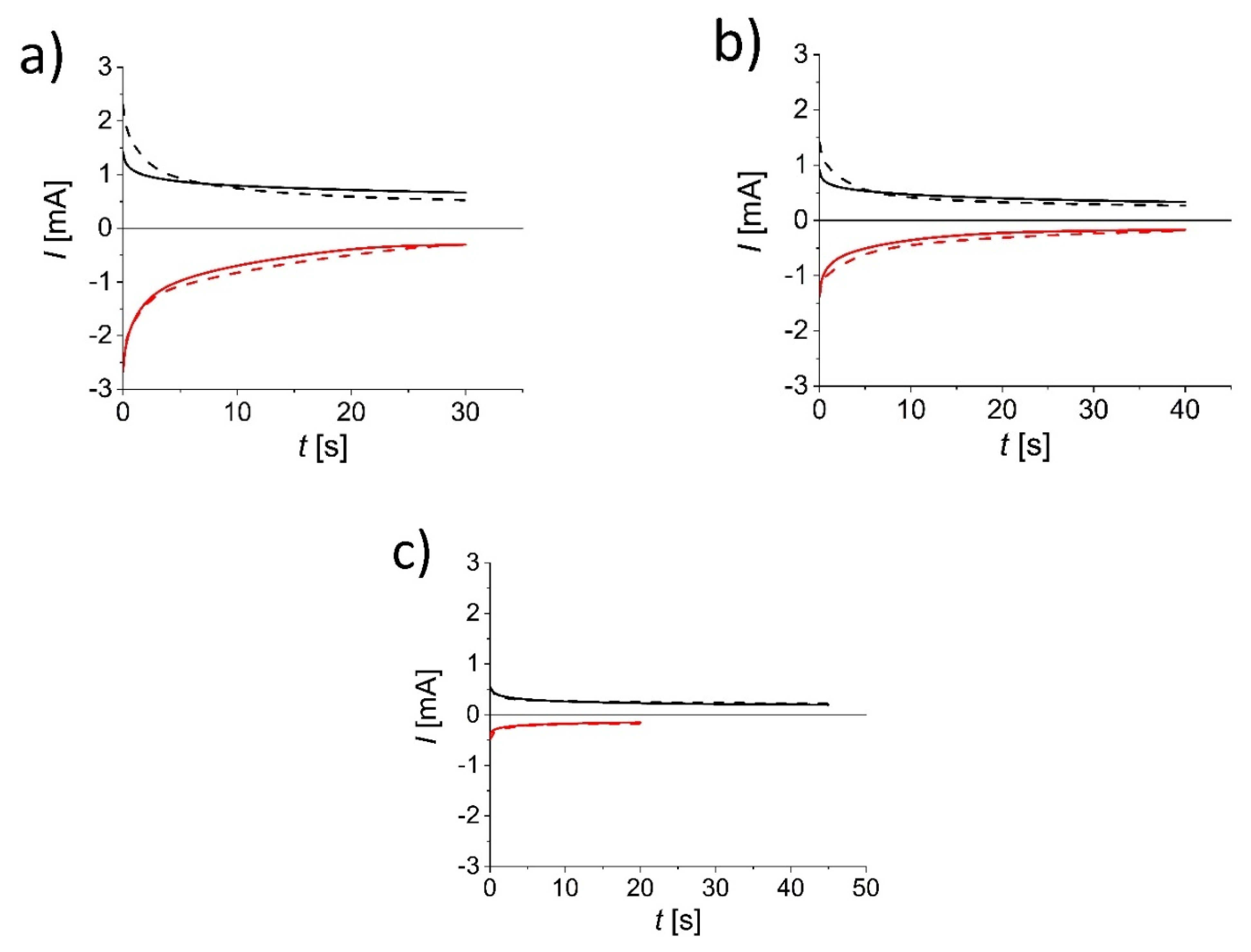
2.5.1. Chronoamperometry

Measurements were performed using a PalmSens4 instrument (PalmSens, Netherlands). Each type of metal oxide ECD used different conditions for optimal cell performance:
  • WO3 device: +3.25 V for tinting and −3.5 V for bleaching, with each pulse lasting for 30 s.
  • V2O5 device: +3.5 V for tinting and −3. 5 V for bleaching, with each pulse lasting for 40 s.
  • TiO2 device: +3.25 V for tinting and −3.25 V for bleaching, with each tinting pulse lasting for 45 s and each bleaching pulse lasting for 20 s.

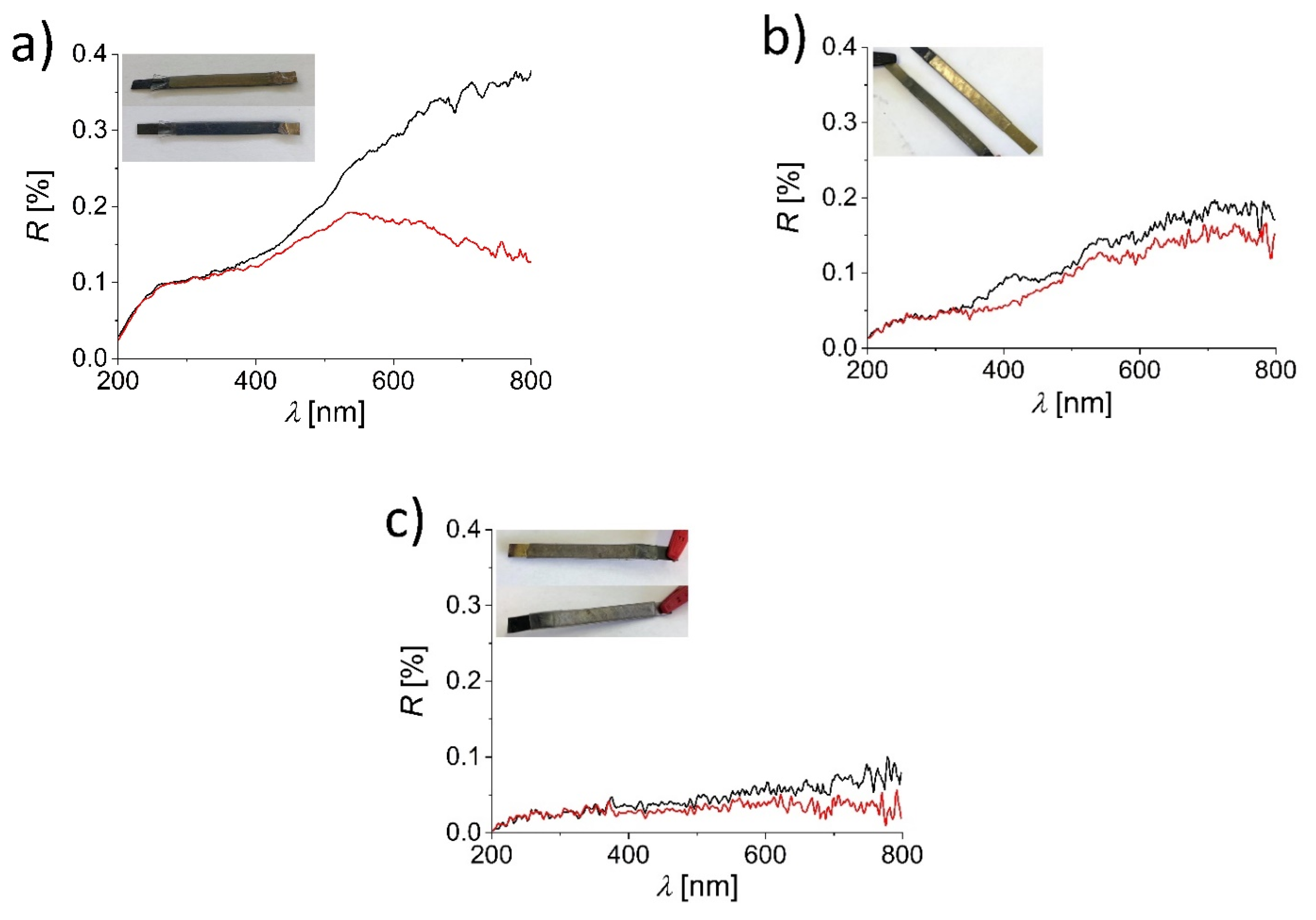
2.5.2. UV–Vis Reflectance Spectrophotometry

Spectra were recorded using a Cary 50 spectrophotometer (Agilent, Santa Clara, California, USA) with an associated probe to measure the reflection on the optical fiber (Agilent, USA). All spectra (both tinted and bleached states) were measured in the wavelength range from 200 to 800 nm with scan speed of 600 nm/min.

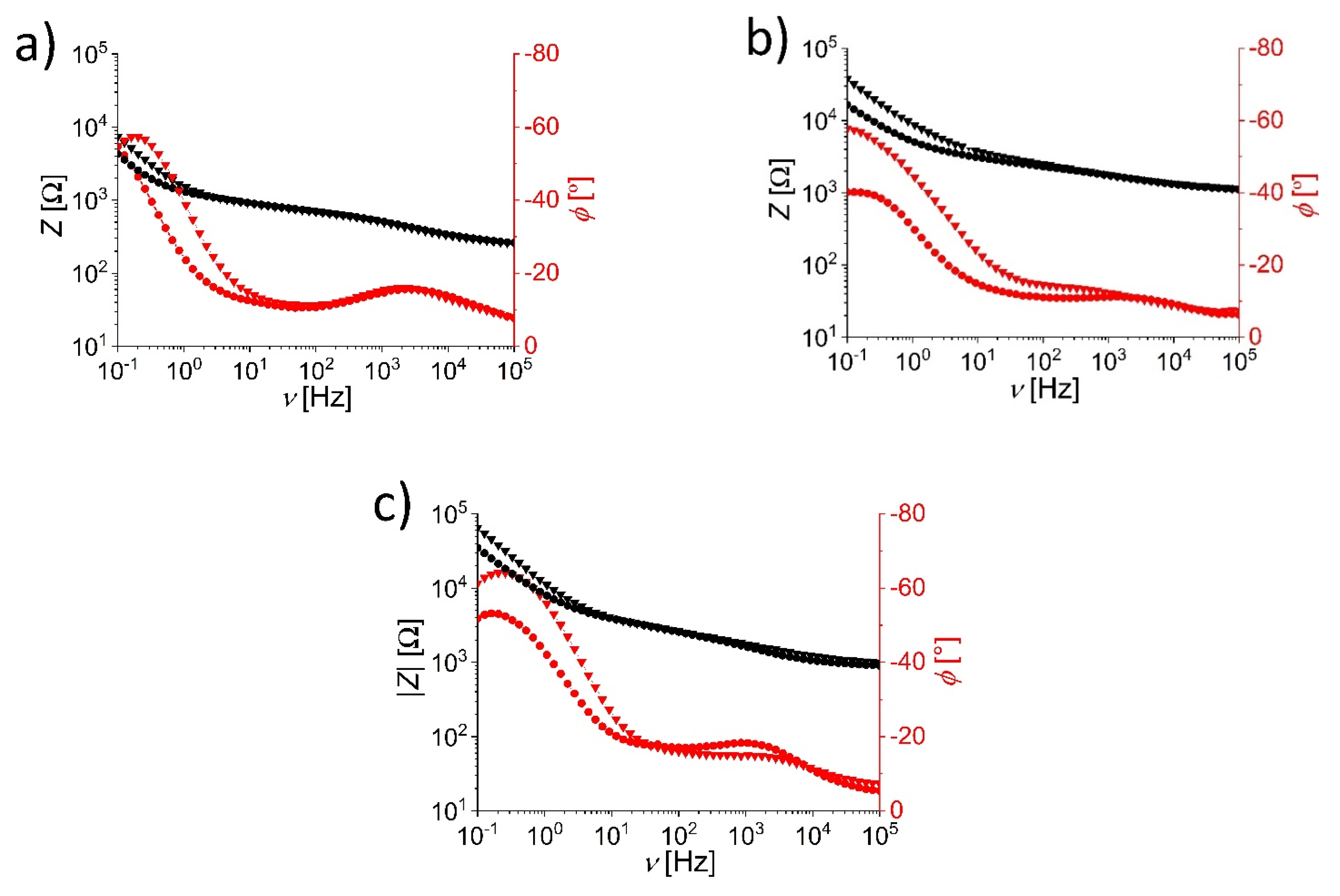
2.5.3. Electrochemical Impedance Spectroscopy (EIS)

EIS measurements were performed with a PalmSens4 instrument (PalmSens, Houten, Netherlands) with an amplitude of 10 mV vs. open circuit potential in the frequency range from 0.1 Hz to 100 kHz. Eight measuring points per decade were recorded.

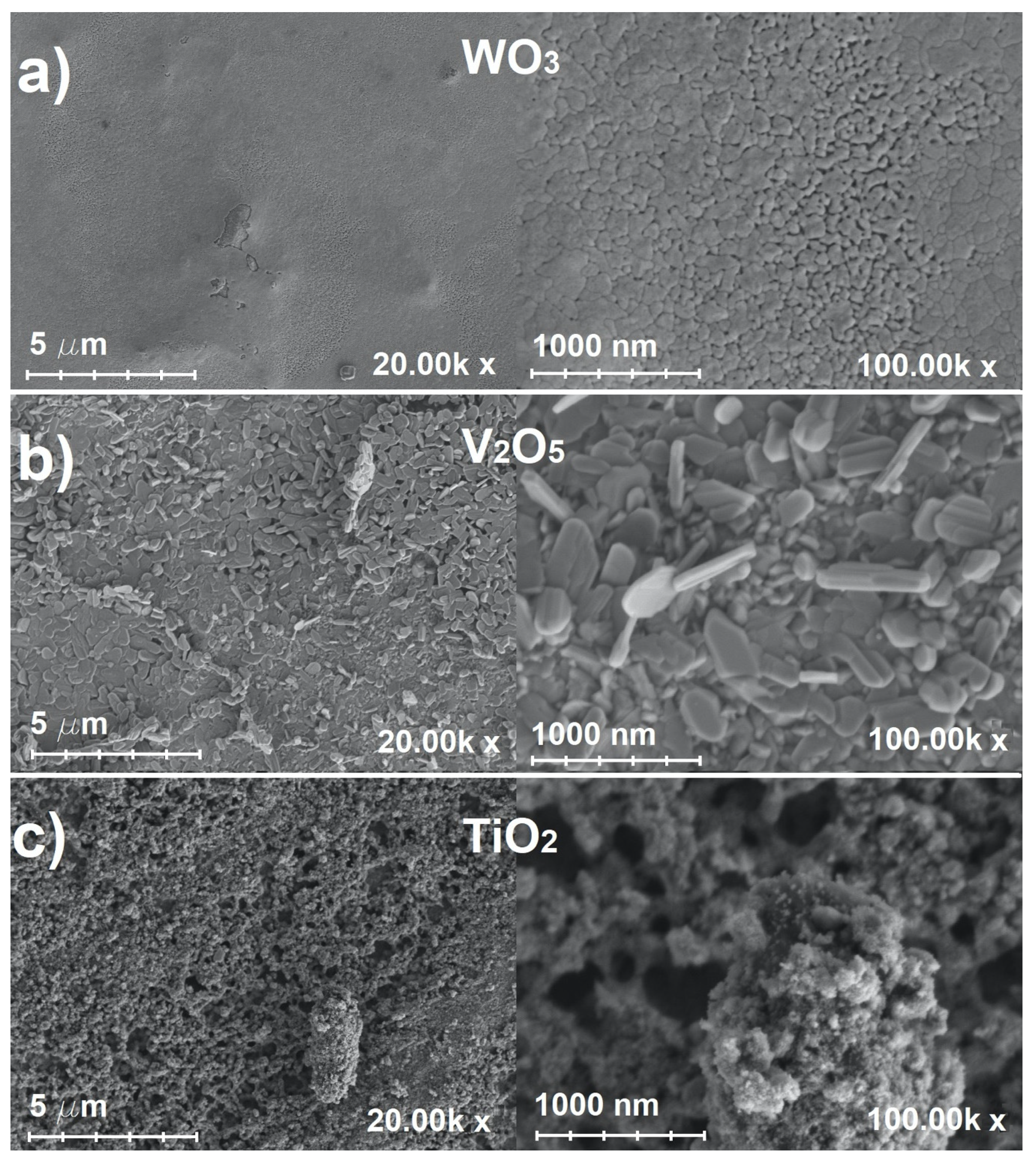
2.5.4. Scanning Electron Microscopy (SEM)

SEM measurements were performed using a Zeiss ULTRA plus field emission microscope (FE-SEM) (Carl Zeiss, Oberkochen, Germany). The accelerating voltage of the electrode when taking microphotographs was 2 kV for all samples.

3. Results and Discussion

3.1. SEM Investigation of Metal Oxide Thin Film–Stainless Steel Electrodes

We begin our the presentation of our results with the structural properties of electrode coatings. A scanning electron microscope (SEM) was used to analyze the morphological features of the metal oxide thin films on stainless steel tapes. Figure 1 shows microphotographs of (a) WO3, (b) V2O5 and (c) TiO2 coatings at 20,000× (left) and 100,000× (right) magnifications.
At low magnification (Figure 1a, left), it can be seen that the coating of WO3 is uniform. Occasional artifacts are due to the rapid evaporation of solvent from the droplets during the early stages of the sintering phase. Higher magnification (Figure 1a, right) shows that the prepared WO3 coating has a distinct pattern of surface tiles separated by cracks, with a more porous layer beneath. However, a bare stainless steel surface is not evident (the prepared thin film covered the electrode uniformly). These artifacts were the result of a relatively short drying phase, but did not have a significant impact on the device performance. In addition, the drying phase was kept short in all three cases to ensure an accurate comparison of results between thin film samples was carried out. Our results are in agreement with the literature data [19,26].
In the case of the V2O5 thin film (Figure 1b), it can be observed that the prepared films are less porous compared to the WO3 thin films, with granule-like structures tightly packed together that can be observed at higher magnification (right panel). The fabricated V2O5 thin films are of comparable quality to previously fabricated thin films reported in the literature [27].
Figure 1c shows a TiO2 thin film on stainless steel. At the higher magnification (right), it is clear that the porosity of TiO2 is larger than that of V2O5 and a sponge-like structure can be seen (even at lower magnification). The fabricated TiO2 thin films are quite comparable to mesoporous thin films reported in the literature [28], indicating that the processes used to fabricate the thin films are interchangeable between ceramic-coated glass substrate and stainless steel foil [29].

3.2. Optical Characterization of ECDs

To analyze the color response of assembled ECDs, UV–Vis reflectance spectra were recorded in the wavelength range between 200 and 800 nm. Data are shown in Figure 2 for devices with (a) WO3, (b) V2O5 and (c) TiO2 thin film–stainless steel electrodes in the bleached (black) and tinted (red) states.
With increasing wavelength, λ , the reflectance, R, increases. The relative increase is most obvious in the case of the WO3-based ECD and the least pronounced in case of the TiO2-based ECD. For the ECD with WO3-coated electrodes, the differences between the spectra of the bleached and tinted states start to appear above 350 nm, and quite significant differences are observed beyond 500 nm. At 800 nm, the difference in reflectance is the largest ( Δ R   ~   0.25 %). In the case of the V2O5-based ECD, the differences between the bleached and tinted states are mainly observed in the range between 350 and 400 nm (~0.05%) and between 600 and 800 nm (reflectance of the tinted state is only slightly higher from the reflectance of the bleached state). Compared to the WO3-based ECD, the color response of the V2O5 device is less visible, although still present, which can also be seen on photographs of the devices (insets in Figure 2). For the ECD made with TiO2-coated stainless steel electrodes, the difference in R between the bleached and tinted states can mainly be seen in the range between 550 ( Δ R   ~   0.02 %) and 800 nm ( Δ R   ~   0.04 %). The much worse electrochromic response of the TiO2 device compared to the WO3 and V2O5 devices is probably the result of a thinner coating compared to tungsten and vanadium oxides.

3.3. Electrochemical Characterization of ECDs

Electrochemical impedance spectroscopy (EIS) measurements were made in order to investigate the differences in the behavior of the metal oxide–stainless steel electrodes. Devices with WO3-, V2O5- and TiO2-coated electrodes in the dimension of 50 × 5 mm2 were tested. Figure 3 shows the Bode graphs, i.e., changes in the impedance vector modulus, | Z | (black) and capacitive phase angle, ϕ (red), as a function of frequency, υ , for ECDs in the bleached (circles) and tinted (triangles) states. A broad range of frequencies was explored (from 10−1 to 105 Hz).
Figure 3 applies to (a) WO3, (b) to V2O5 and (c) to TiO2 ECDs. In all three cases of ECDs, the Bode graphs show quite similar behavior: the impedance increases with a decreasing frequency, with an increase observed at the low-frequency region (below~3 Hz), where the difference between the tinted and bleached states becomes obvious. The impedance is higher for the tinted state and at 0.1 Hz reaches 7.5 kΩ for WO3 and up to 40 and 70 kΩ for V2O5 and TiO2, respectively. In the tinted state, the lithium ions are doped into the metal oxide lattice. This decreases the concentration of Li+ in the electrolyte and increases the impedance (resistance) of the tinted stated compared to the bleached state. The resistive behavior is predominant in the low-frequency range.
The behavior of WO3 thin film on a stainless steel electrode can be correlated to the intercalation reaction, as described in the literature [1]. This is also in accordance with the phase angle data: below 100 Hz, differences in ϕ for the bleached and tinted states become obvious, while the phase angle at high frequencies has similar values for both states. For υ < 1 Hz, the phase angle for the bleached state monotonically increases with the decreasing frequency, while for the tinted state, it reaches a maximum value at 0.2 Hz and then starts to decrease.
In the case of the V2O5 thin film electrode, the difference in the impedance between the tinted and bleached states can be observed at lower frequencies, indicating that the electrochromic reaction could again be due to the intercalation mechanism. A minor change in phase angle at very high frequencies (above 10 kHz) could suggest there is a possible redox reaction; however, since there is no difference in impedance, this is less likely. Redox reaction influence, however, can be reconsidered, since it was reported in the previous literature [30]. In addition, phase angle values at low frequencies (at 0.1 Hz, the difference is almost 20°) are much higher compared to the WO3 thin film electrode, suggesting changes in surface morphology, which could be due to such color changing reactions. However, due to the absence of any phase angle change in the region between 1 kHz and 10 kHz, this is considered less likely.
For the TiO2 thin film electrode, the impedance differences between the tinted and the bleached states are observed at both high (>200 Hz) and low (<2 Hz) frequencies. An intercalation process similar to the behavior in WO3 can be observed at low frequencies. Marked differences in the phase angles for the bleached and tinted states can be observed almost in the whole frequency range, with amplification in the low frequency range (<200 Hz). The impedance data at the lower-frequency region (below 2 Hz) clearly indicate the intercalation process; however, both impedance and phase angle data at higher frequencies (above 10 kHz) suggest there is a strong redox reaction, which in this case can be directly correlated to corrosion of stainless steel electrodes. Corrosion can be due to much thinner TiO2 films compared to WO3 and V2O5 electrodes, and can also be observed in reflectance data, where TiO2-coated electrodes (Figure 2c) exhibited much lower reflectance values compared to other two metal oxides. The EIS measurements confirm differences in the electrode processes taking place in WO3, V2O5 and TiO2 thin-film-coated stainless steel electrodes in tinted and bleached states. These can be observed as different absolute impedance and phase angle values in the low-frequency region (below 2 Hz). They point toward surface change on electrodes that happens when devices are tinted. However, one should also note that differences in the EIS response could be due to the thickness of the metal oxide films. The optimization of the coating method used in this work or the use of alternative coating methods (e.g., inkjet printing [31], spray coating [32]) to ensure the same layer thickness in all cases would be required in future work.

3.4. Chronoamperometry

Chronoamperometry measurements at selected working conditions were performed in order to test the stability of all assembled devices. Data are shown in Figure 4 for devices with (a) WO3-, (b) V2O5- and (c) TiO2-coated electrodes. All of the devices were cycled 50 times.
In the case of the WO3 ECD, at the first cycle, the initial staining current (+3.25 V) was about 1.5 mA and reached a value of about 0.75 mA after 30 s. For bleaching (−3.5 V), the initial current reached a value of about −2.75 mA and changed to −0.5 mA after 30 s. In the following cycles, a higher initial current was observed (around 2.5 mA) but reached the same value of about 0.75 mA at the end. The presented data show that there are no major differences in the current profile between the first and fiftieth cycle, along with no decrease in coloration response.
For the ECD with V2O5-coated stainless steel electrodes, each of the cycles lasted 40 s. For the first cycle, the initial staining current (+3.5 V) was 0.9 mA and reached a value of about 0.4 mA after 40 s. For decolorization (−3.5 V), the initial current reached a value of about −1.1 mA and after 40 s reached a value of −0.2 mA. In case of the 50th cycle, the current increased by about 10% for tinting, with an initial current value of 1.4 mA, while for bleaching, the overall current was increased by around 5 to 10%. Although the current values increased, there was no visible change in coloration response during cycling.
For the ECD assembled with TiO2, each tinting pulse lasted 45 s, while each bleaching pulse lasted 20 s. For the first cycle, the initial staining current (+3.25 V) was 0.6 mA and reached a value of about 0.2 mA after 45 s. For decolorization (−3.25 V), the initial current reached a value of about −0.9 mA and after 20 s reached a value of −0.2 mA. During the cycling, the current increased for less than 5%; however, coloration was hardly observed and distinguished. As it was observed from previous data, it is speculated that low coloration response is due to a very thin layer of TiO2 that was applied on the surface.

4. Conclusions

Stainless steel foil was coated with a thin film of WO3, V2O5 or TiO2. The metal oxide–stainless steel electrodes were used to construct ECDs with inverted sandwich geometry, and a Li-based electrolyte was used. Such electrochromic tapes are more flexible and mechanically resistant than the conventional devices based on optically transparent electrodes. The constructed ECDs differed in their optical and electrochemical response. The most optimal ECD consisted of WO3-based electrodes because the porosity and physical properties of the WO3 thin film allowed for the maximum intercalation of Li+ ions into the resulting layer. The cell showed distinct changes in color between the tinted and bleached states. Good cycling stability and reversibility of the WO3-based ECD was achieved at 3.25/−3.5 V (30 s for the color change). The V2O5-based ECD also showed a fairly good response (40 s for the color change at 4.5/−4.5 V). In this case, the redox reactions that took place during tinting/bleaching were mainly responsible for the color response of the cell. In the case of the ECD consisting of TiO2-coated electrodes, better results were expected, since Li+ ions can be intercalated into the TiO2 layer, similar to WO3. Unfortunately, our TiO2-based ECD showed only marginal coloration response, which can be attributed to the insufficient thickness of the electrochromic TiO2 thin layer on the stainless steel substrate.
In the future, to improve the performance of the devices, the coating process would need to be optimized to ensure sufficient thickness of the metal oxide layers, and electrolytes with better redox properties would need to be tested.

Author Contributions

Conceptualization, M.R., U.B. and M.L.; methodology, M.R.; software, M.R. and N.C.; validation, M.R and N.C.; formal analysis, M.R, N.C., U.B. and M.L.; investigation, M.R, N.C., U.B. and M.L; resources, M.R., U.B. and M.L.; data curation, M.R. and N.C.; writing—original draft preparation, M.R. and N.C.; writing—review and editing, U.B. and M.L.; visualization, M.R.; supervision, M.R., U.B. and M.L.; project administration, M.R., U.B. and M.L.; funding acquisition, U.B. and M.L. All authors have read and agreed to the published version of the manuscript.

Funding

This research was funded by the Slovenian Research Agency (ARRS): core project numbers P1-0201 and J1-2471.

Data Availability Statement

Data can be obtained directly from authors upon reasonable request.

Acknowledgments

Authors would like to thank B. Žener for his help with SEM images and R. Fuchs-Godec for the discussion regarding EIS data.

Conflicts of Interest

The authors declare no conflict of interest.

References

  1. Monk, P.; Mortimer, R.; Rosseinsky, D. Electrochromism and Electrochromic Devices; Cambridge University Press (CUP): Cambridge, UK, 2007. [Google Scholar]
  2. Sakamoto, R.; Nishihara, H. Electrochromic and photochromic properties. In Comprehensive Inorganic Chemistry II, 2nd ed.; Reedijk, J., Poeppelmeier, K., Eds.; Elsevier: Amsterdam, The Netherlands, 2013; pp. 919–967. [Google Scholar]
  3. Monk, P.M.S. Electrochromism and electrochromic materials for displays. In Handbook of Advanced Electronic and Photonic Materials and Devices; Singh Nalwa, H., Ed.; Academic Press: Burlington, NJ, USA, 2001; pp. 105–159. [Google Scholar]
  4. Gélinas, B.; Das, D.; Rochefort, D. Air-Stable, Self-Bleaching Electrochromic Device Based on Viologen- and Ferrocene-Containing Triflimide Redox Ionic Liquids. ACS Appl. Mater. Interfaces 2017, 9, 28726–28736. [Google Scholar] [CrossRef]
  5. Wang, K.; Tao, K.; Jiang, R.; Zhang, H.; Liang, L.; Gao, J.; Cao, H. A Self-Bleaching Electrochromic Mirror Based on Metal Organic Frameworks. Materials 2021, 14, 2771. [Google Scholar] [CrossRef]
  6. Ming, S.; Lin, K.; Zhang, H.; Jiang, F.; Liu, P.; Xu, J.; Nie, G.; Duan, X. Electrochromic polymers with multiple redox couples applied to monitor energy storage states of supercapacitors. Chem. Commun. 2020, 56, 5275–5278. [Google Scholar] [CrossRef]
  7. Roy, S.; Chakraborty, C. Sub-second electrochromic switching and ultra-high coloration efficiency in halloysite nanoclay incorporated metallo-supramolecular polymer nano-hybrid based electrochromic device. Sol. Energy Mater. Sol. Cells 2020, 208, 110392. [Google Scholar] [CrossRef]
  8. Lv, X.; Zha, L.; Qian, L.; Xu, X.; Bi, Q.; Xu, Z.; Wright, D.S.; Zhang, C. Controllable fabrication of perylene bisimide self-assembled film and patterned all-solid-state electrochromic device. Chem. Eng. J. 2020, 386, 123939. [Google Scholar] [CrossRef]
  9. Svensson, J.; Granqvist, C. Electrochromic tungsten oxide films for energy efficient windows. Sol. Energy Mater. 1984, 11, 29–34. [Google Scholar] [CrossRef]
  10. Passerini, S.; Scrosati, B.; Gorenstein, A. The Intercalation of Lithium in Nickel Oxide and Its Electrochromic Properties. J. Electrochem. Soc. 1990, 137, 3297–3300. [Google Scholar] [CrossRef] [Green Version]
  11. Ghicov, A.; Tsuchiya, H.; Hahn, R.; Macak, J.; Muñoz, A.G.; Schmuki, P. TiO2 nanotubes: H+ insertion and strong electrochromic effects. Electrochem. Commun. 2006, 8, 528–532. [Google Scholar] [CrossRef]
  12. Dini, D.; Decker, F.; Masetti, E. A comparison of the electrochromic properties of WO3 films intercalated with H+, Li+ and Na+. J. Appl. Electrochem. 1996, 26, 647–653. [Google Scholar] [CrossRef]
  13. Rozman, M.; Gaberšček, M.; Marolt, G.; Bren, U.; Luksic, M. An inverted sandwich electrochromic device architecture does not require optically transparent electrodes. Adv. Mater. Technol. 2019, 4, 1900389. [Google Scholar] [CrossRef]
  14. Park, S.-I.; Quan, Y.-J.; Kim, S.-H.; Kim, H.; Kim, S.; Chun, D.-M.; Lee, C.S.; Taya, M.; Chu, W.-S.; Ahn, S.-H. A review on fabrication processes for electrochromic devices. Int. J. Precis. Eng. Manuf. Technol. 2016, 3, 397–421. [Google Scholar] [CrossRef]
  15. Kundu, S. Electrochromic Materials Used to Make Smart Glass in Airplane Windows Could Have Widespread Uses. Available online: https://www.forbes.com/sites/forbes-personal-shopper/2020/06/12/best-thermometers-available-for-purchase-online-right-now (accessed on 31 August 2016).
  16. Yang, P.; Sun, P.; Mai, W. Electrochromic energy storage devices. Mater. Today 2016, 19, 394–402. [Google Scholar] [CrossRef]
  17. Christie, R. Chromic materials for technical textile applications. In Advances in the Dyeing and Finishing of Technical Textiles; Elsevier: Amsterdam, The Netherlands, 2013; pp. 3–36. [Google Scholar]
  18. Rozman, M. Izdelava in Karakterizacija Elektrokemijskih Sistemov za Elektrokromne in Fotovoltaične Aplikacije Doc; Lukšič, M., Ed.; Univerza v Ljubljani: Ljubljana, Slovenia, 2017; p. 66. [Google Scholar]
  19. Rozman, M.; Žener, B.; Matoh, L.; Godec, R.F.; Mourtzikou, A.; Stathatos, E.; Bren, U.; Lukšič, M. Flexible electrochromic tape using steel foil with WO3 thin film. Electrochim. Acta 2020, 330, 135329. [Google Scholar] [CrossRef]
  20. Rozman, M.L.; Gaberšček, P.M. Jovanovič Elektrokromna Celica, Sestavljena iz Dveh Neprosojnih Elektrod ter Nosilca Elektrolita z Dodanim Elektrokromnim Barvilom. Patent SI 25127 a, 31 July 2017. [Google Scholar]
  21. Krašovec, U.O.; Orel, B.; Georg, A.; Wittwer, V. The gasochromic properties of sol–gel WO3 films with sputtered Pt catalyst. Sol. Energy 2000, 68, 541–551. [Google Scholar] [CrossRef]
  22. Livage, J.; Guzman, G.; Beteille, F.; Davidson, P. Optical properties of sol-gel derived vanadium oxide films. J. Sol.-Gel. Sci. Technol. 1997, 8, 857–865. [Google Scholar] [CrossRef]
  23. Stathatos, E.; Lianos, P.; Lavrencic-Stangar, U.; Orel, B. A High-Performance Solid-State Dye-Sensitized Photoelectrochemical Cell Employing a Nanocomposite Gel Electrolyte Made by the Sol–Gel Route. Adv. Mater. 2002, 14, 354–357. [Google Scholar] [CrossRef]
  24. Shibata, M.; Kawashita, K.-I.; Yosomiya, R.; Gongzheng, Z. Electrochromic properties of polypyrrole composite films in solid polymer electrolyte. Eur. Polym. J. 2001, 37, 915–919. [Google Scholar] [CrossRef]
  25. Puetz, J.; Aegerter, M.A. Dip coating technique. In Sol-Gel Technologies for Glass Producers and Users; Aegerter, M.A., Mennig, M., Eds.; Springer US: Boston, MA, USA, 2004; pp. 37–48. [Google Scholar]
  26. Greenwood, O.; Moulzolf, S.; Blau, P.; Lad, R. The influence of microstructure on tribological properties of WO3 thin films. Wear 1999, 232, 84–90. [Google Scholar] [CrossRef]
  27. Liu, Y.; Li, J.; Zhang, Q.; Zhou, N.; Uchaker, E.; Cao, G. Porous nanostructured V2O5 film electrode with excellent Li-ion intercalation properties. Electrochem. Commun. 2011, 13, 1276–1279. [Google Scholar] [CrossRef]
  28. Stathatos, E.; Choi, H.; Dionysiou, D.D. Simple Procedure of Making Room Temperature Mesoporous TiO2 Films with High Purity and Enhanced Photocatalytic Activity. Environ. Eng. Sci. 2007, 24, 13–20. [Google Scholar] [CrossRef]
  29. Rozman, M.; Cerar, J.; Lukšič, M.; Uršič, M.; Mourtzikou, A.; Spreizer, H.; Škofic, I.K.; Stathatos, E. Electrochromic properties of thin nanocrystalline TiO 2 films coated electrodes with adsorbed Co(II) or Fe(II) 2,2′-bipyridine complexes. Electrochim. Acta 2017, 238, 278–287. [Google Scholar] [CrossRef]
  30. Costa, C.; Pinheiro, C.; Henriques, I.; Laia, C. Electrochromic Properties of Inkjet Printed Vanadium Oxide Gel on Flexible Polyethylene Terephthalate/Indium Tin Oxide Electrodes. ACS Appl. Mater. Interfaces 2012, 4, 5266–5275. [Google Scholar] [CrossRef] [PubMed]
  31. Bernacka-Wojcik, I.; Wojcik, P.; Aguas, H.; Fortunato, E.; Martins, R. Inkjet printed highly porous TiO2 films for improved electrical properties of photoanode. J. Colloid Interface Sci. 2016, 465, 208–214. [Google Scholar] [CrossRef] [PubMed]
  32. Castro, Y.; Mosa, J.; Aparicio, M.; Pérez-Carrillo, L.A.; Vílchez, S.; Esquena, J.; Durán, A. Sol–gel hybrid membranes loaded with meso/macroporous SiO2, TiO2–P2O5 and SiO2–TiO2–P2O5 materials with high proton conductivity. Mater. Chem. Phys. 2015, 149, 686–694. [Google Scholar] [CrossRef]
Figure 1. Scanning electron microscope microphotographs of (a) WO3, (b) V2O5 and (c) TiO2 thin films on stainless steel at 20,000× (left) and 100,000× (right) magnification.
Electronics 10 02529 g001
Figure 2. UV–Vis reflectance spectra of the investigated ECDs with (a) WO3, (b) V2O5 and (c) TiO2 thin-film-coated stainless steel electrodes in bleached (black) and tinted (red) states. Inset shows photographic images of the device in both states.
Electronics 10 02529 g002
Figure 3. Bode plots for the inverted sandwich electrochromic devices with (a) WO3, (b) V2O5 and (c) TiO2 thin film–stainless steel electrodes in bleached (squares) and tinted (triangles) states. Frequency dependence of the impedance vector modulus, | Z | , is given in black, and of the phase angle, ϕ , in red color.
Electronics 10 02529 g003
Figure 4. Chronoamperograms of the 1st (continuous line) and 50th (dashed line) cycle for the bleaching (red) and tinting (black) process for (a) WO3, (b) V2O5 and (c) TiO2 thin film–stainless steel electrodes.
Electronics 10 02529 g004
Publisher’s Note: MDPI stays neutral with regard to jurisdictional claims in published maps and institutional affiliations.

