Research and Analysis of Permanent Magnet Transmission System Controls on Diesel Railway Vehicles

Abstract
1. Introduction
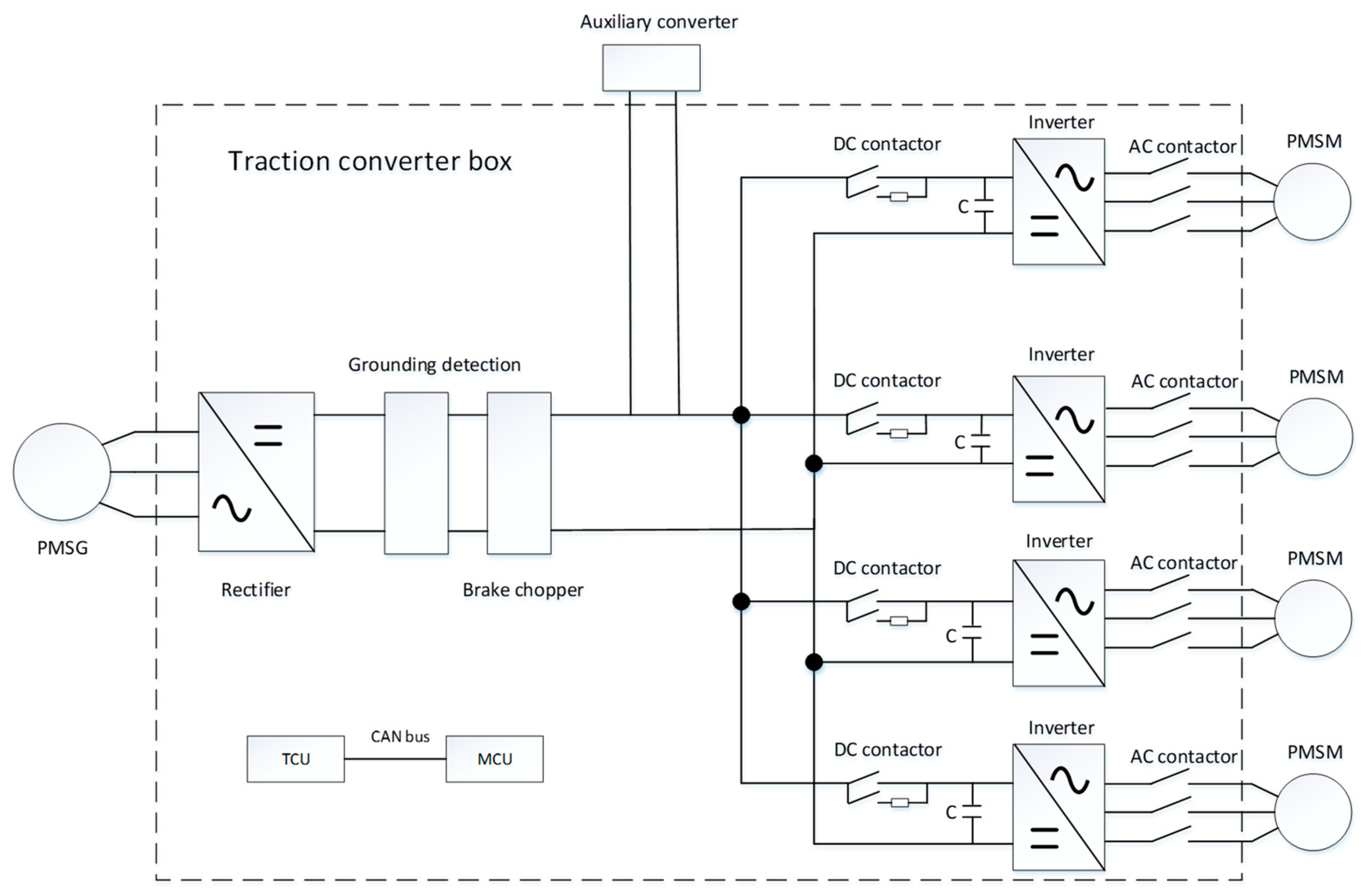
2. Constitution and Features of FPMTS
3. Control and Protection Strategy
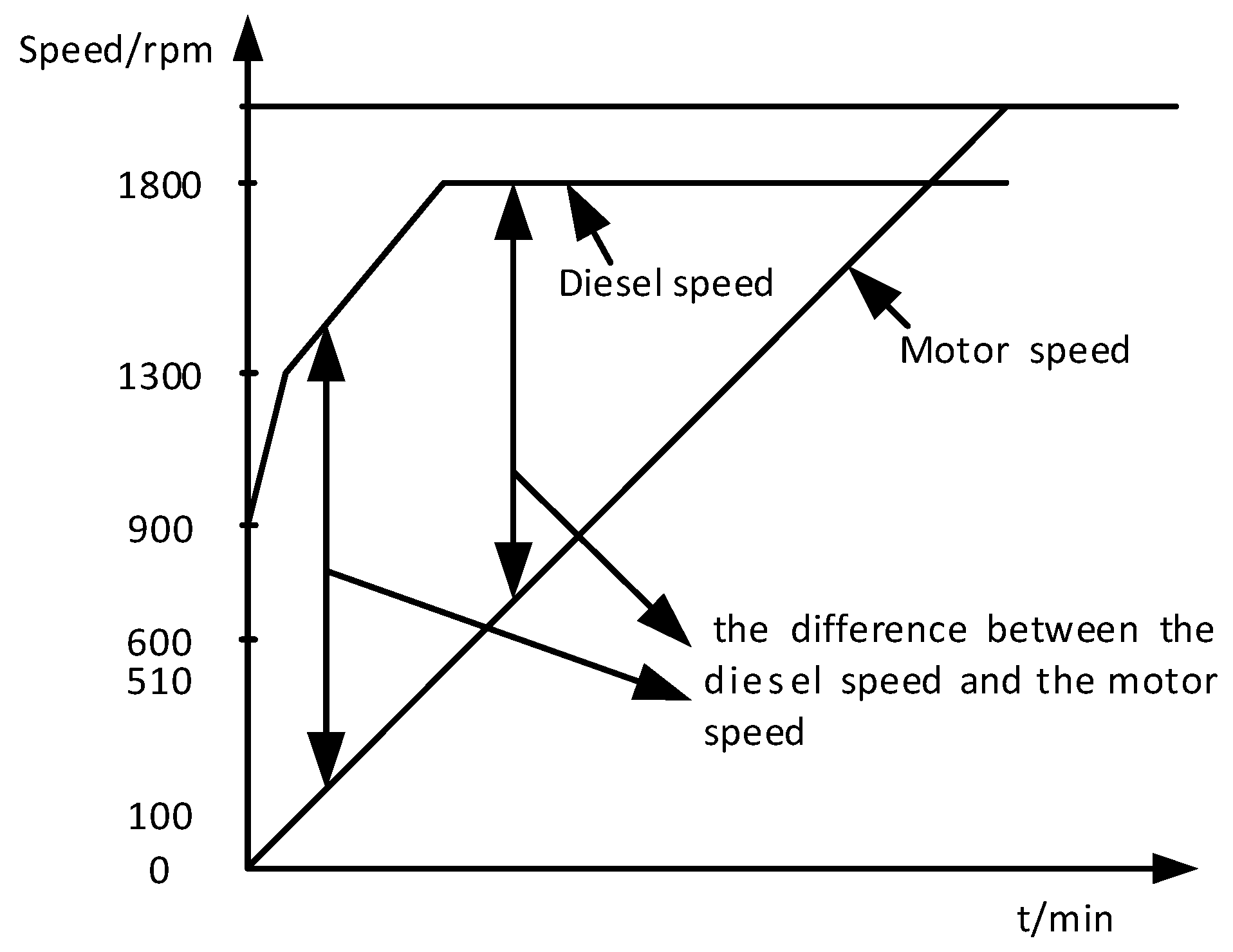
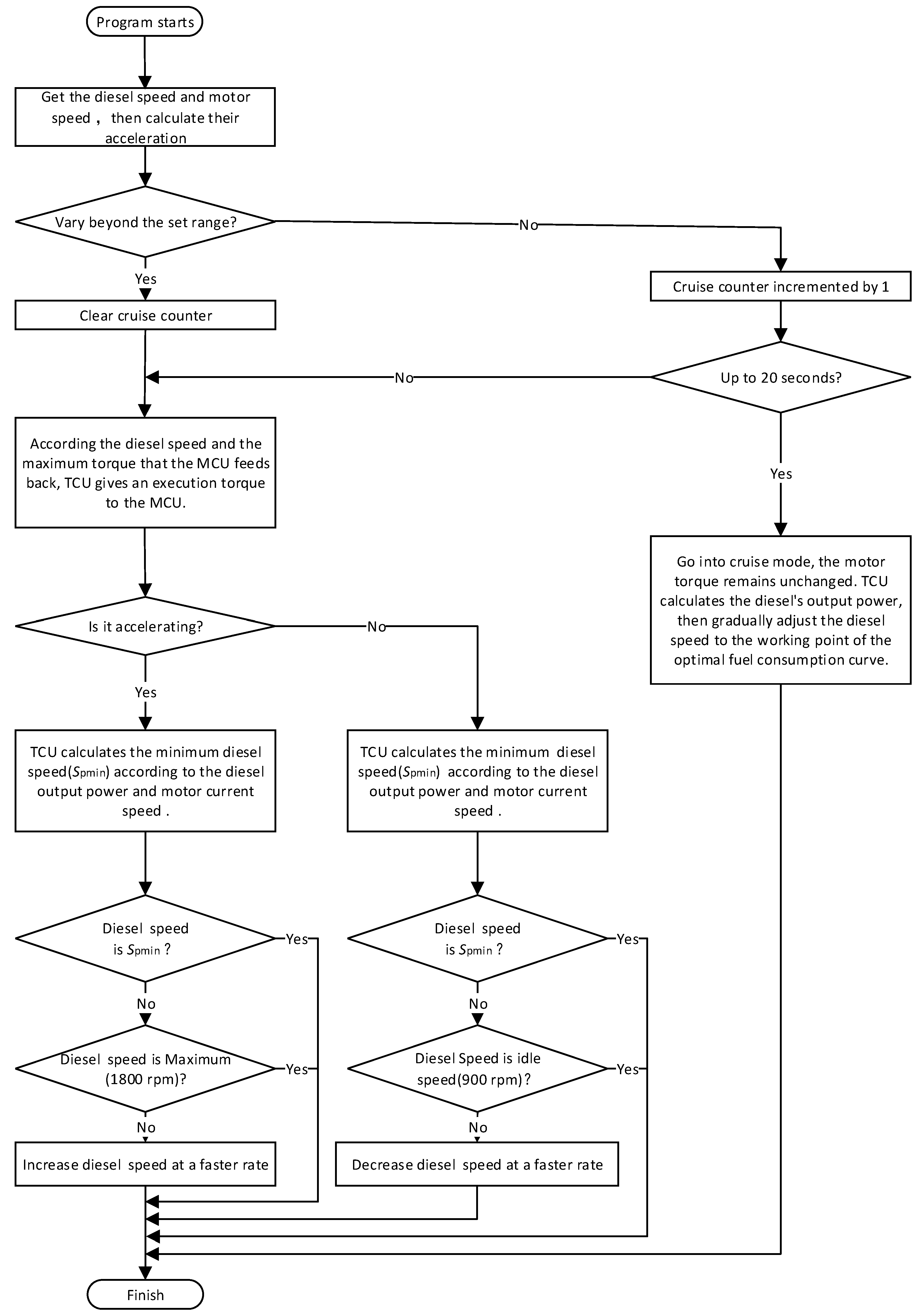
3.1. Coordinated Control of Diesel and Traction Motor
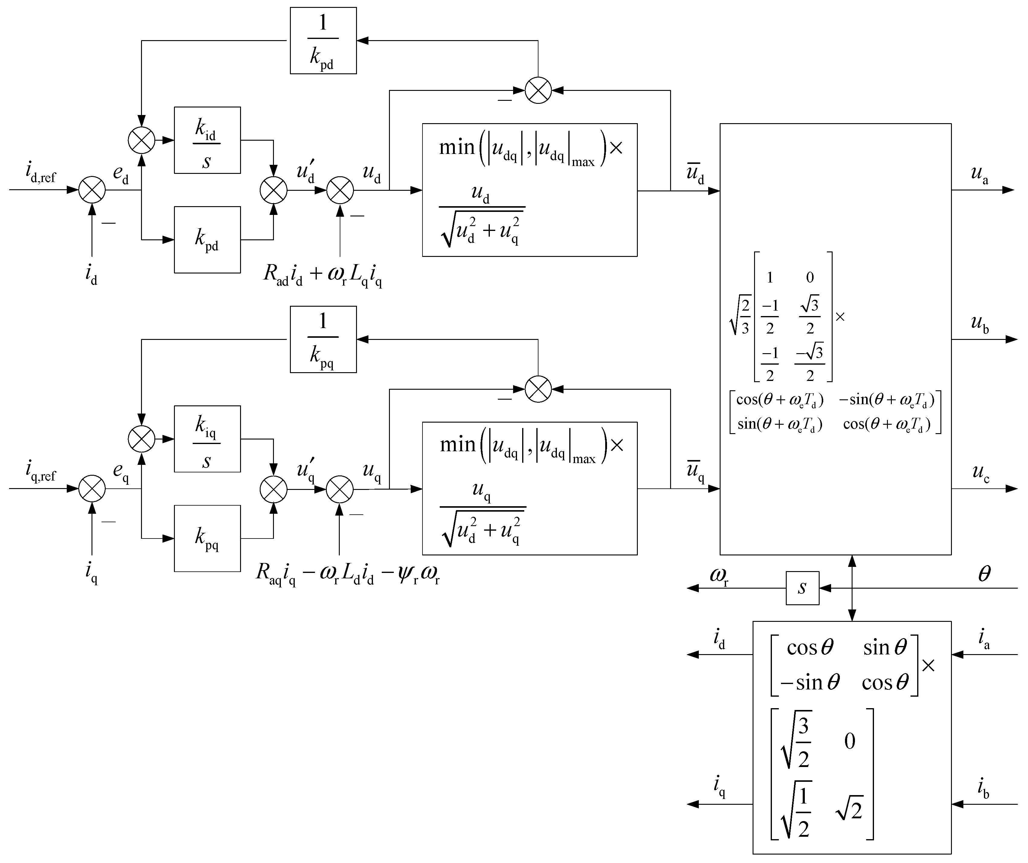
3.2. Design of the 2DOF Decoupling Current Regulator
3.3. Maximum Torque Control of a Standardized Unit Current
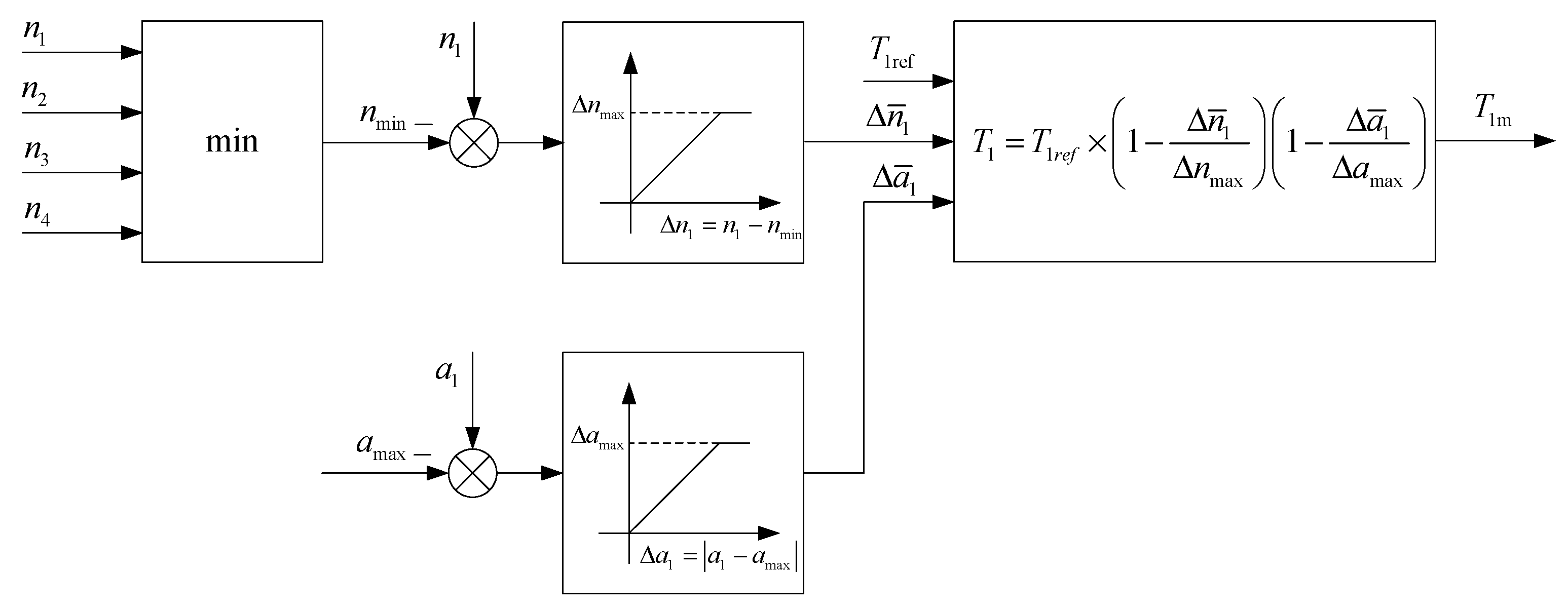
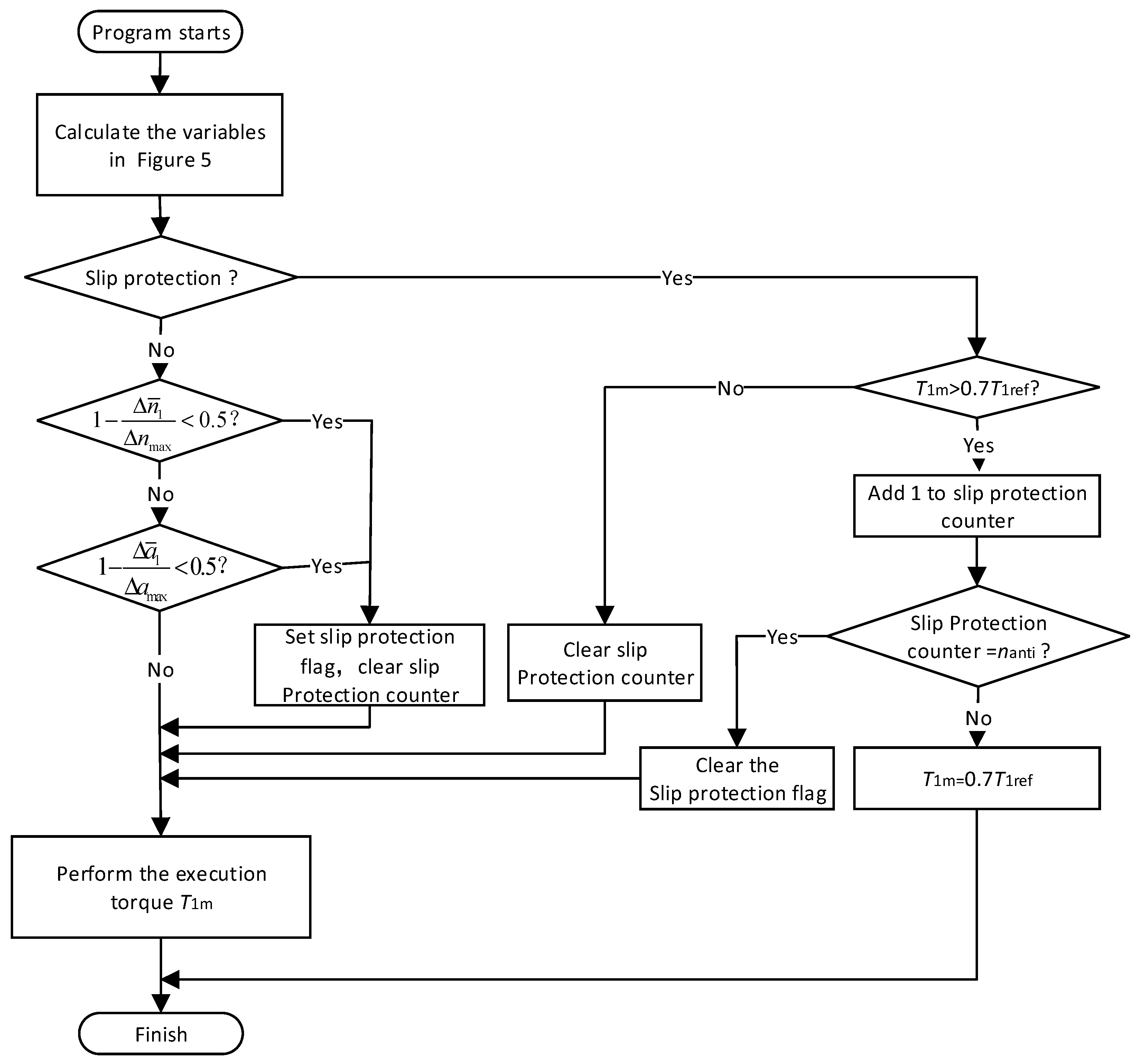
3.4. Wheel Slip Protection Control Strategy
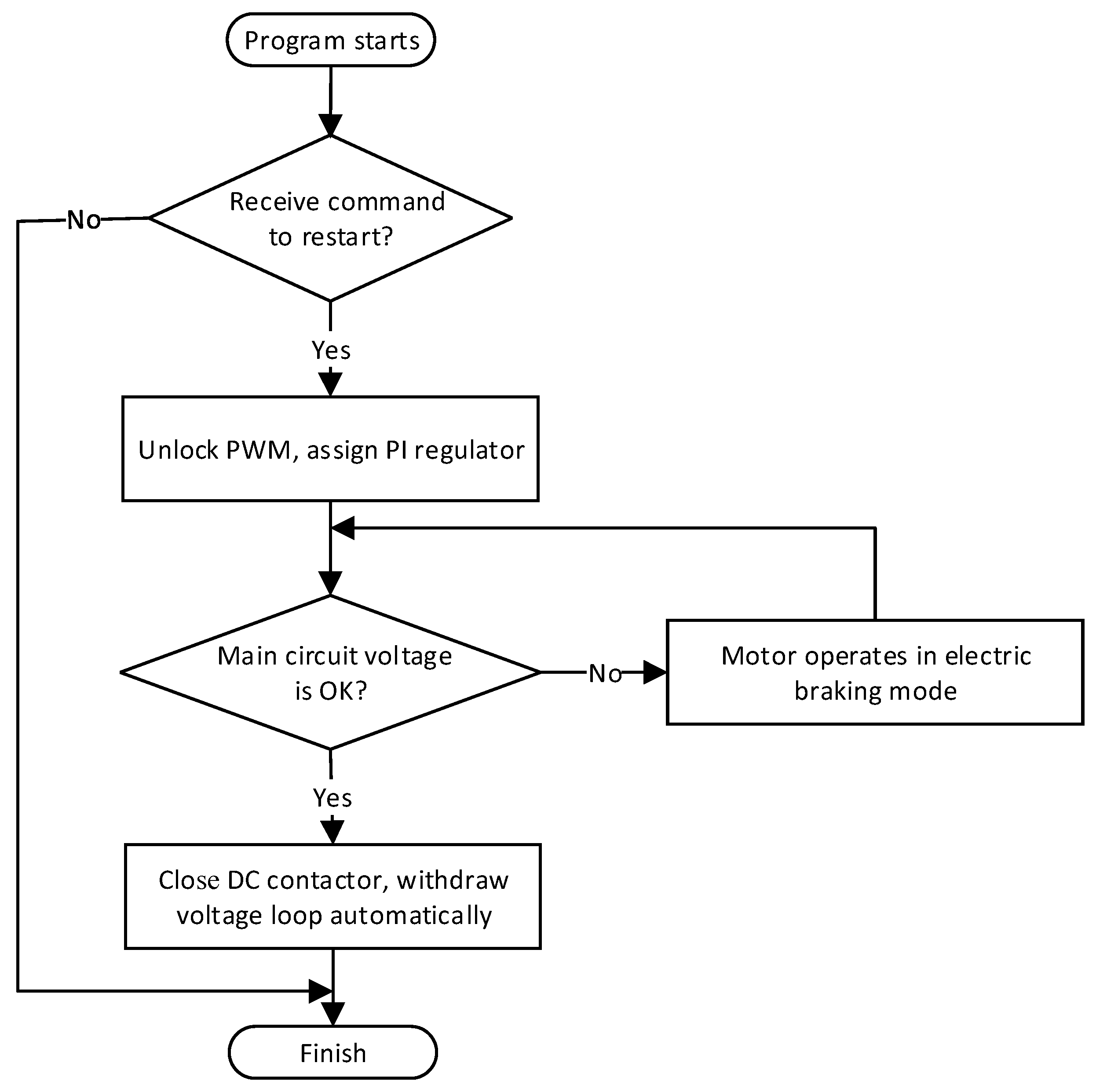
3.5. Fault Detection and Restart Control
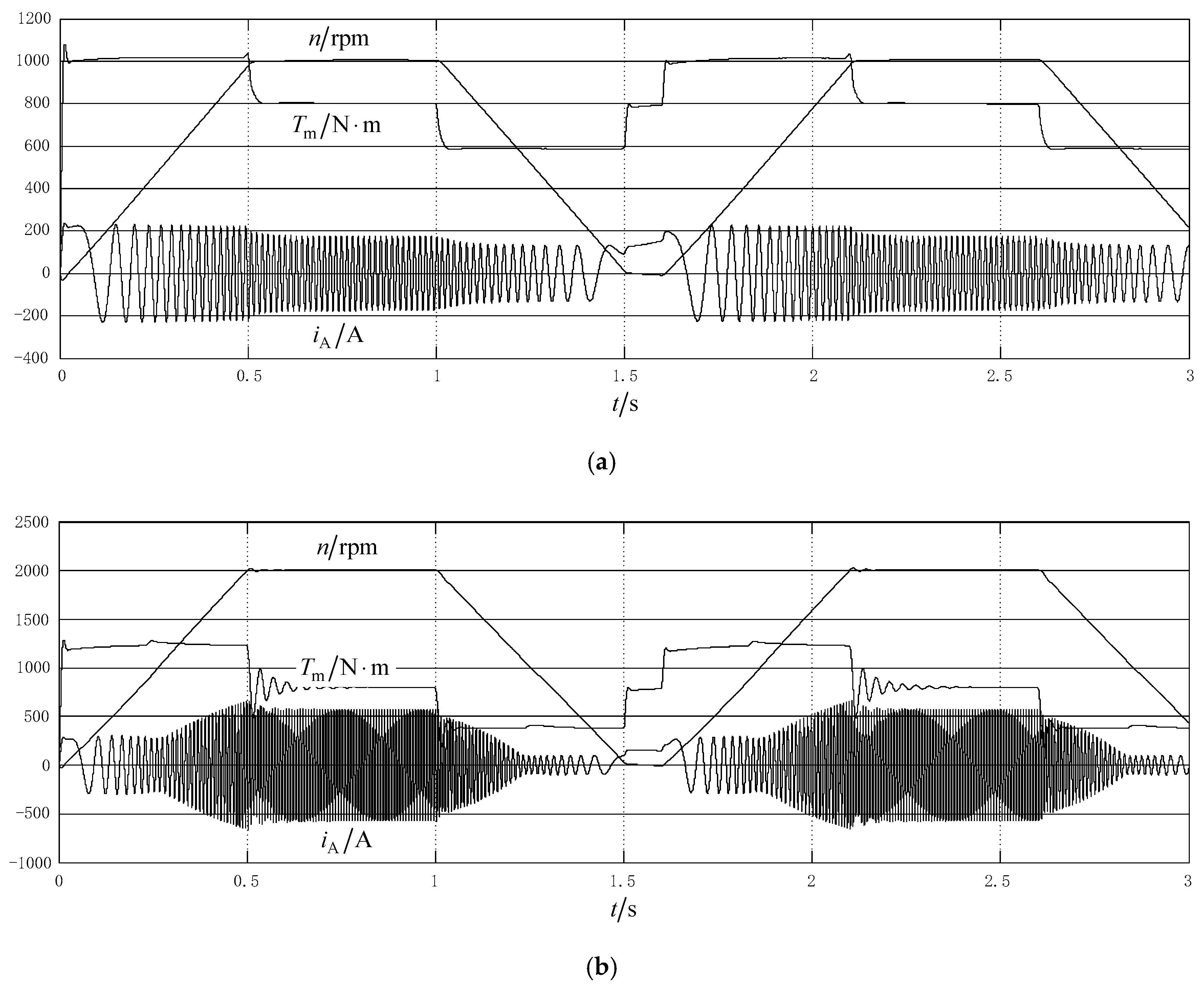
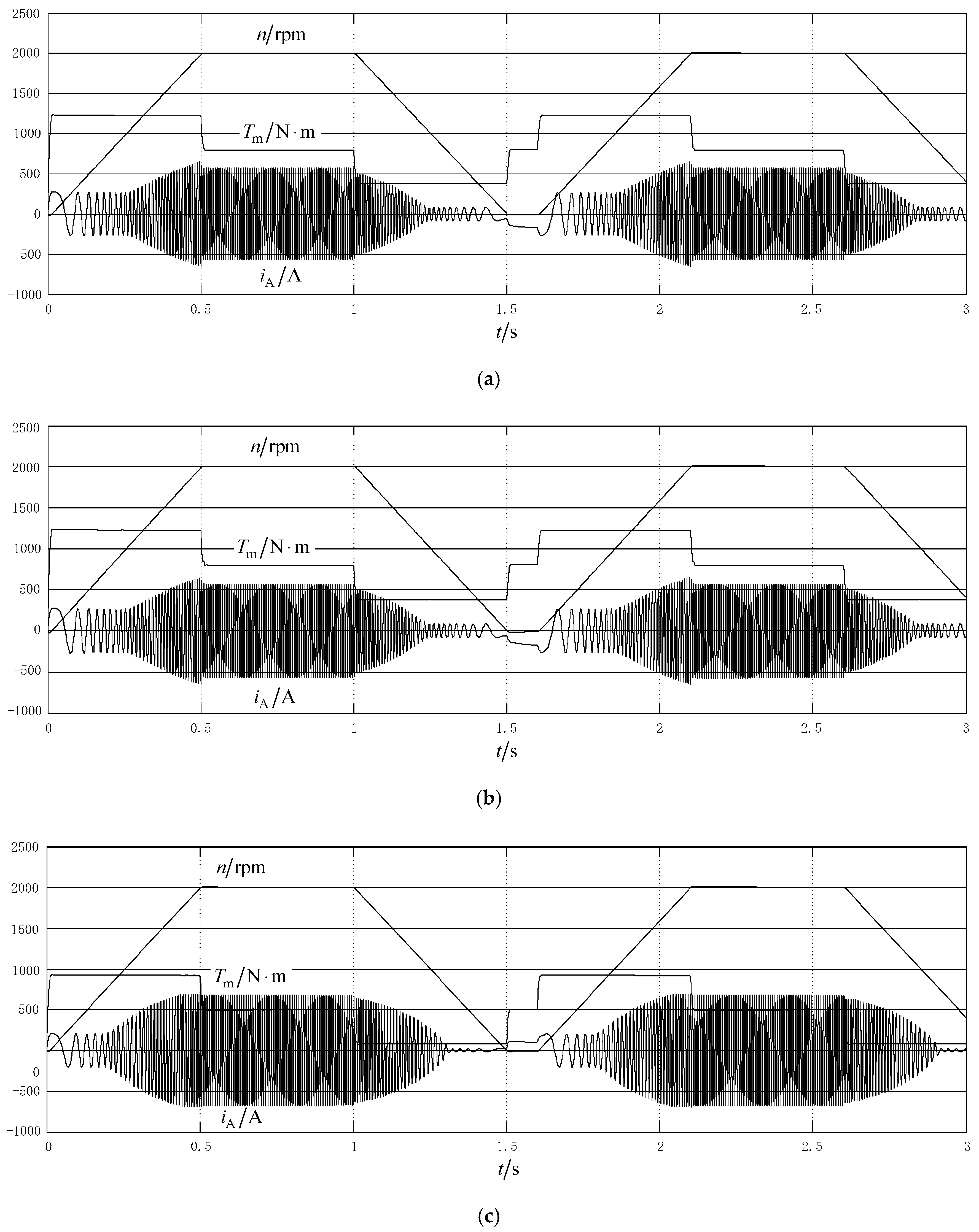
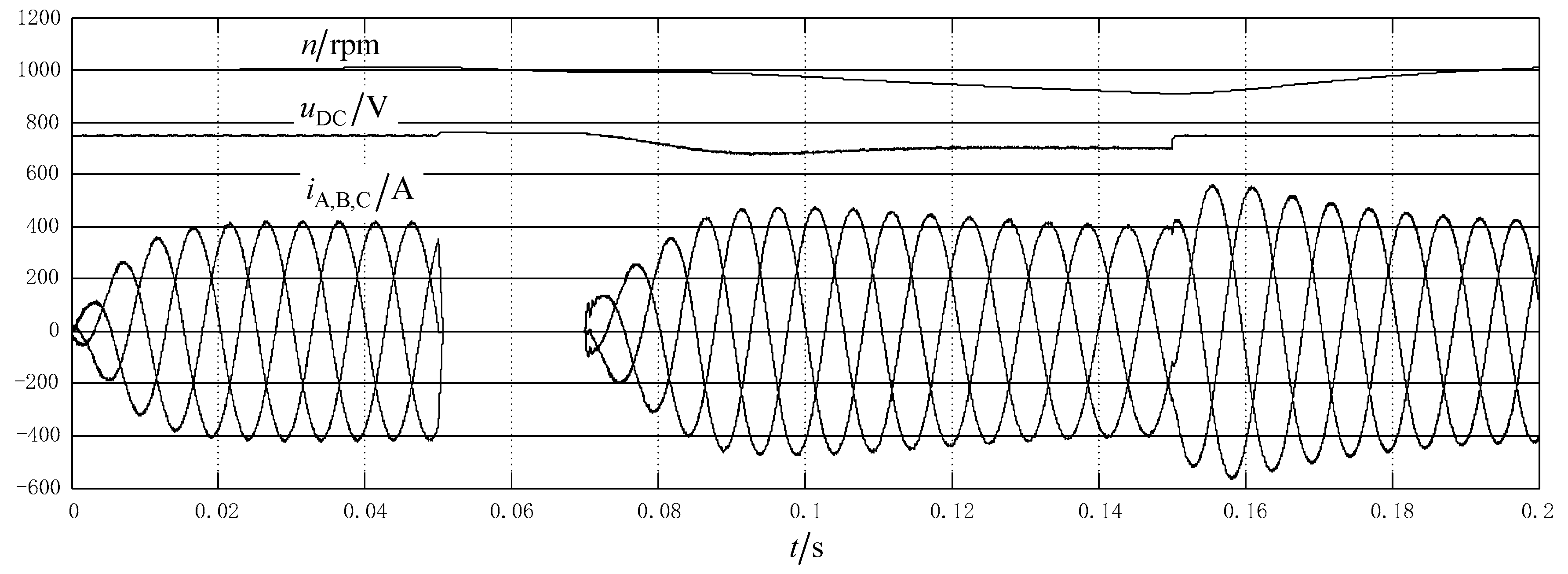
4. Simulation
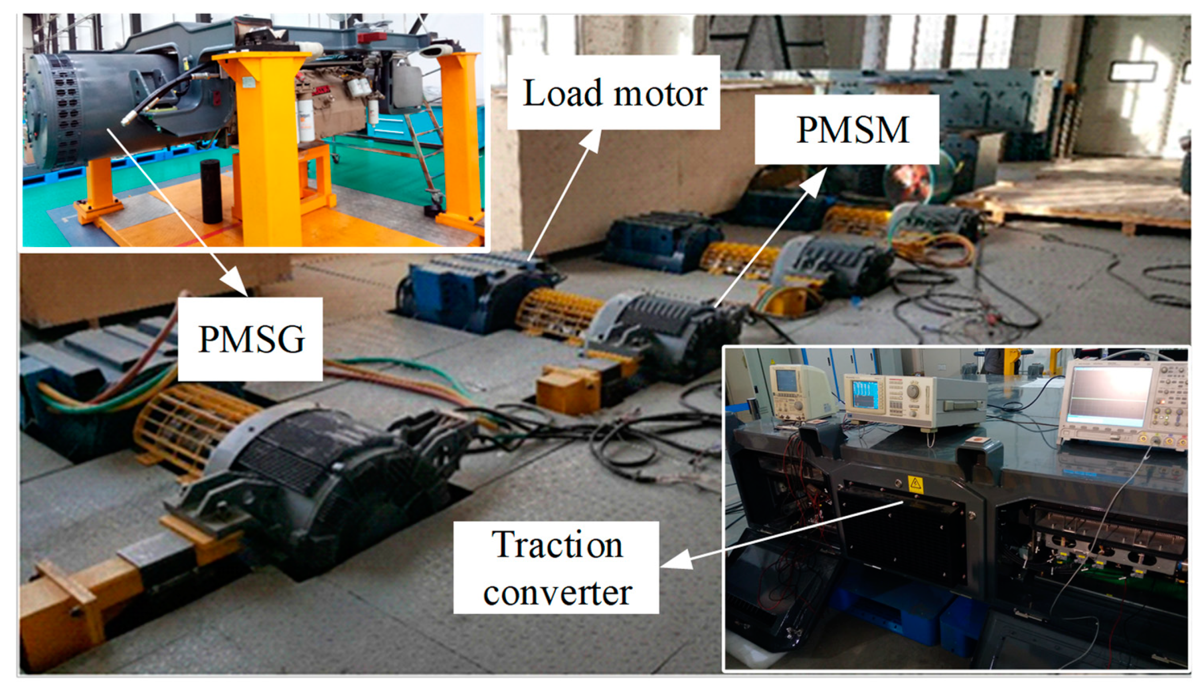
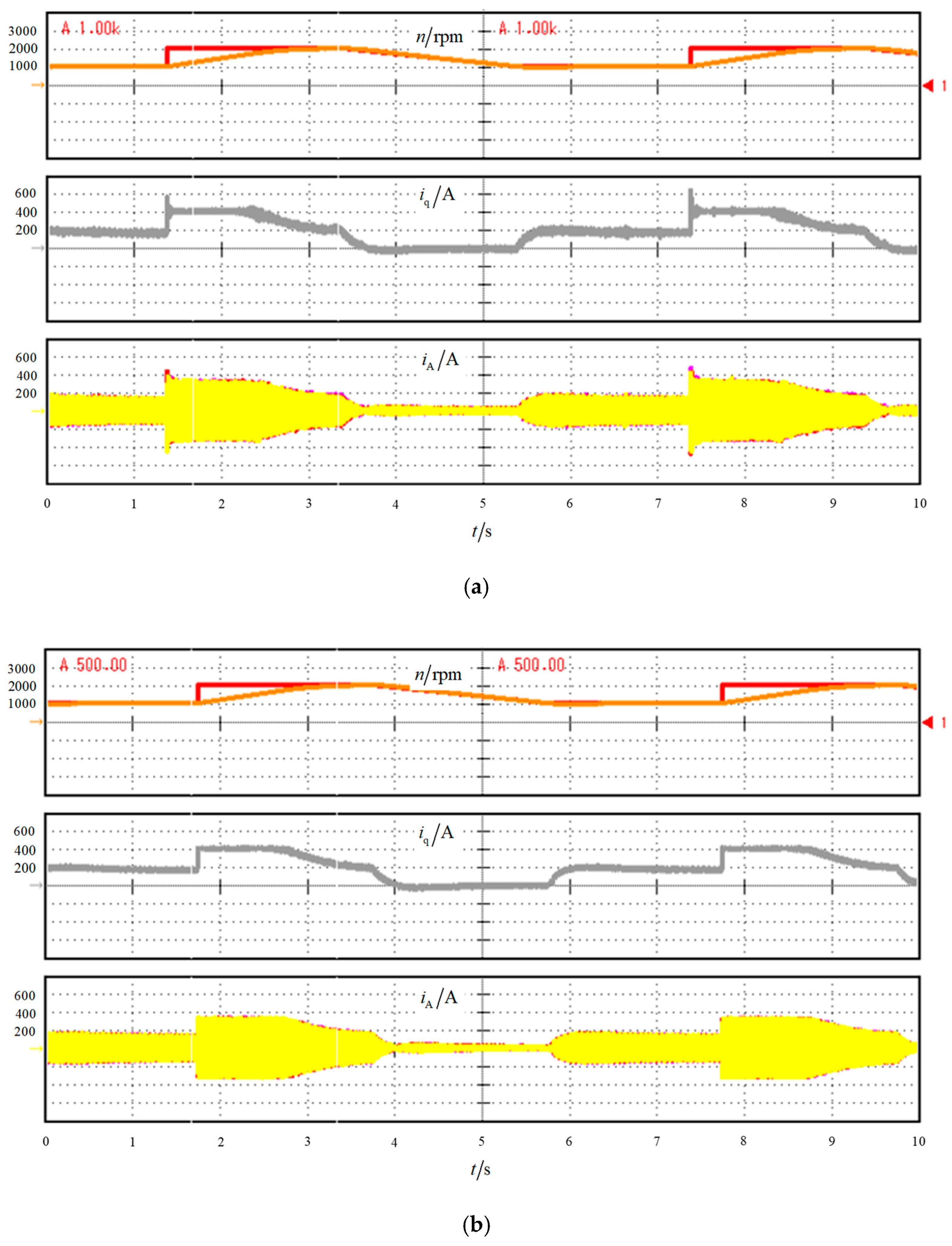
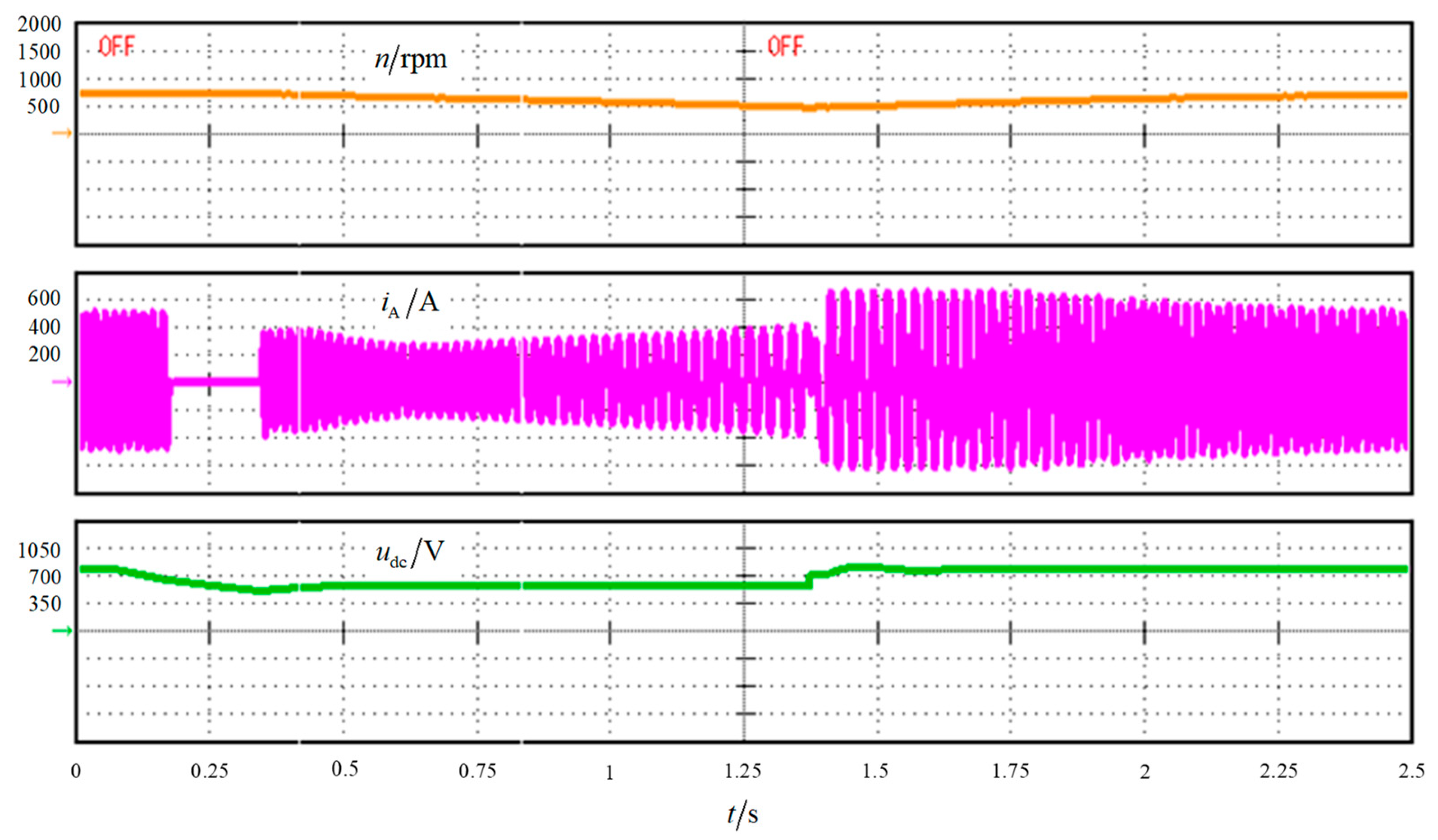
5. Experiment
6. Conclusions
Author Contributions
Funding
Data Availability Statement
Acknowledgments
Conflicts of Interest
References
- van der Meulen, D.; Möller, F. Sustainable heavy haul traction energy: A review of systemic issues. Proc. Inst. Mech. Eng. Part F J. Rail Rapid Transit 2014, 228, 687–694. [Google Scholar] [CrossRef]
- Shiraki, N.; Satou, H.; Arai, S. A hybrid system for diesel railcar series Ki-Ha E200. In Proceedings of the 2010 International Power Electronics Conference (IPEC 2010), Sapporo, Japan, 21–24 June 2010; pp. 2853–2858. [Google Scholar]
- Schmid, S.; Ebrahimi, K.; Pezouvanis, A.; Commerell, W. Model-based comparison of hybrid propulsion systems for railway diesel multiple units. Int. J. Rail Transp. 2018, 6, 16–37. [Google Scholar] [CrossRef]
- International Union of Railways; International Energy Agency. Railway Handbook 2017; International Energy Agency: Paris, France, 2017. [Google Scholar]
- Shamardina, V.N.; Anishchenko, M.V.; Lemeshko, S.M.; Kanunnikov, R.V. Functional efficiency enhancement of diesel-electric locomotive traction system. In Proceedings of the 2017 International Conference on Modern Electrical and Energy Systems (MEES 2017), Kremenchuk, Ukraine, 15–17 November 2017; pp. 20–23. [Google Scholar]
- Germishuizen, J.; Jockei, A.; Hoffmann, T.; Teichmann, M.; Lowenstein, L.; Wangelin, F.V. SyntegraTM—Next generation traction drive system, total integration of traction, bogie and braking technology. In Proceedings of the 2006 International Symposium on Power Electronics, Electrical Drives, Automation and Motion(SPEEDAM 2006), Taormina, Italy, 23–26 May 2006; pp. 1073–1077. [Google Scholar]
- Binder, A.; Koch, T. Permanent magnet gearless traction drive for German high speed train ICE 3. In Proceedings of the 2001 International Conference on Power Electronics (ICPE 2001), Seoul, Korea, 30 May–3 June 2011; pp. 756–760. [Google Scholar]
- Shikata, K.; Kawai, H.; Nomura, H.; Aoki, H.; Fukasawa, S.; Tasaka, Y. PMSM propulsion system for Tokyo Metro. In Proceedings of the 2012 Electrical Systems for Aircraft, Railway and Ship Propulsion (ESARS 2012), Bologna, Italy, 16–18 October 2012. [Google Scholar]
- Jianghua, F. Development Overview and Application Challenges of Permanent Magnet Synchronous Traction System for Rail Transit. High Power Convert. Technol. 2012, 3, 1–7. [Google Scholar]
- Matsuoka, K. Development trend of the permanent magnet synchronous motor for railway traction. IEEJ Trans. Electr. Electron. Eng. 2007, 2, 154–161. [Google Scholar] [CrossRef]
- Ito, T.; Inaba, H.; Kishine, K.; Nakai, M.; Ishikura, K. Method controlling four sets of permanent magnet synchronous motor by one inverter on a railway vehicle. In Proceedings of the 2014 17th International Conference on Electrical Machines and Systems (ICEMS 2014), Hangzhou, China, 22–25 October 2014; pp. 245–249. [Google Scholar]
- Roumani, K.; Schmuelling, B. Topology selection for low voltage PMSM for in-wheel direct-drive application. In Proceedings of the 2017 19th International Conference on Electrical Drives and Power Electronics (EDPE 2017), Dubrovnik, Croatia, 4–6 October 2017; pp. 235–241. [Google Scholar]
- Sheng, Y.; Zhou, W.; Hong, Z.; Yu, S. Field weakening operation control of permanent magnet synchronous motor for railway vehicles based on maximum electromagnetic torque at full speed. In Proceedings of the 29th Chinese Control Conference, Beijing, China, 29–31 July 2010; pp. 1608–1613. [Google Scholar]
- Calleja, C.; López-de-Heredia, A.; Gaztañaga, H.; Aldasoro, L.; Nieva, T. Validation of a modified direct-self-control strategy for PMSM in railway-traction applications. IEEE Trans. Ind. Electron. 2016, 63, 5143–5155. [Google Scholar] [CrossRef]
- Zhao, K.; She, J.; Zhang, C.; He, J.; Huang, G.; Liu, J. Robust Closed-loop Torque Control for PMSM of Railway Traction Considering Demagnetization. In Proceedings of the IECON 2019-45th Annual Conference of the IEEE Industrial Electronics Society, Lisbon, Portugal, 14–17 October 2019; pp. 6916–6921. [Google Scholar]
- Taniguchi, S.; Yasui, K.; Yuki, K.; Nakazawa, Y.; Onda, S. A Restart Control Method for Position Sensorless PMSM Drive Systems Without Potential Transformer for Railway Vehicle Traction. Electr. Eng. Jpn. 2015, 193, 44–53. [Google Scholar] [CrossRef]
- Zhao, S.; Huang, X.; Fang, Y.; Li, J. A control scheme for a High Speed Railway traction system based on high power PMSM. In Proceedings of the 2015 6th International Conference on Power Electronics Systems and Applications (PESA 2015), Hong Kong, China, 15–17 December 2015; pp. 1–8. [Google Scholar]
- Zhang, Z.; Ge, X.; Tian, Z.; Zhang, X.; Tang, Q.; Feng, X. A pwm for minimum current harmonic distortion in metro traction pmsm with saliency ratio and load angle constrains. IEEE Trans. Power Electron. 2017, 33, 4498–4511. [Google Scholar] [CrossRef]
- Jahns, T.M.; Kliman, G.B.; Neumann, T.W. Interior permanent-magnet synchronous motors for adjustable-speed drives. IEEE Trans. Ind. Appl. 1986, 738–747. [Google Scholar] [CrossRef]
- Kim, H.; Hartwig, J.; Lorenz, R.D. Using on-line parameter estimation to improve efficiency of IPM machine drives. In Proceedings of the 2002 IEEE 33rd Annual IEEE Power Electronics Specialists Conference, Cairns, Australia, 23–27 June 2002; pp. 815–820. [Google Scholar]
- Nguyen, Q.K.; Petrich, M.; Roth-Stielow, J. Implementation of the MTPA and MTPV control with online parameter identification for a high speed IPMSM used as traction drive. In Proceedings of the 2014 International Power Electronics Conference (IPEC 2014), Hiroshima, Japan, 18–21 May 2014; pp. 318–323. [Google Scholar]
- Li, F.; Xia, C. Inductance Identification Algorithm and Variable-Parameters MTPA Control Strategy for IPMSM Considering Magnetic Circuit Saturation. Diangong Jishu Xuebao/Trans. China Electrotech. Soc. 2017, 32, 136–144. [Google Scholar]


| Parameter | Value | Parameter | Value |
|---|---|---|---|
| Diesel idle speed (r/min) | 900 | PMSM rated speed (r/min) | 510 |
| Diesel rated speed (r/min) | 1800 | PMSM maximum speed (r/min) | 2000 |
| PMSG rated power (kW) | 560 | PMSM Rated torque (Nm) | 1800 |
| PMSG rated current (A) | 630 | PMSM maximum torque (Nm) | 3200 |
| PMSG rated voltage (V) | 520 | Inverter maximum current (A) | 700 |
| DC link rated Voltage (V) | 750 | PMSM stator resistance (Ω) | 0.013 |
| PMSM rated power (kW) | 100 | PMSM d-axis inductance (mH) | 0.72 |
| PMSM rated current (A) | 270 | PMSM q-axis inductance (mH) | 1.54 |
Publisher’s Note: MDPI stays neutral with regard to jurisdictional claims in published maps and institutional affiliations. |
© 2021 by the authors. Licensee MDPI, Basel, Switzerland. This article is an open access article distributed under the terms and conditions of the Creative Commons Attribution (CC BY) license (http://creativecommons.org/licenses/by/4.0/).
Share and Cite
Kang, L.; Jiang, D.; Xia, C.; Xu, Y.; Sun, K. Research and Analysis of Permanent Magnet Transmission System Controls on Diesel Railway Vehicles. Electronics 2021, 10, 173. https://doi.org/10.3390/electronics10020173
Kang L, Jiang D, Xia C, Xu Y, Sun K. Research and Analysis of Permanent Magnet Transmission System Controls on Diesel Railway Vehicles. Electronics. 2021; 10(2):173. https://doi.org/10.3390/electronics10020173
Chicago/Turabian StyleKang, Lili, Dongjie Jiang, Chaoying Xia, Yongjiu Xu, and Kaiyi Sun. 2021. "Research and Analysis of Permanent Magnet Transmission System Controls on Diesel Railway Vehicles" Electronics 10, no. 2: 173. https://doi.org/10.3390/electronics10020173
APA StyleKang, L., Jiang, D., Xia, C., Xu, Y., & Sun, K. (2021). Research and Analysis of Permanent Magnet Transmission System Controls on Diesel Railway Vehicles. Electronics, 10(2), 173. https://doi.org/10.3390/electronics10020173