Article

K-means Cluster Algorithm Applied for Geometric Shaping Based on Iterative Polar Modulation in Inter-Data Centers Optical Interconnection

1
State Key Laboratory of Information Photonics and Optical Communications, School of Electronic Engineering, Beijing University of Posts and Telecommunications (BUPT), Xitucheng Road NO. 10, Beijing 100876, China
2
Beijing Key Laboratory of Space-Round Interconnection and Convergence, School of Electronic Engineering, Beijing University of Posts and Telecommunications (BUPT), Xitucheng Road NO. 10, Beijing 100876, China
3
Institute of Multidisciplinary Science, Beijing Institute of Technology, Beijing 100081, China
*
Authors to whom correspondence should be addressed.
Electronics 2021, 10(19), 2417; https://doi.org/10.3390/electronics10192417
Submission received: 26 July 2021 / Revised: 16 September 2021 / Accepted: 30 September 2021 / Published: 3 October 2021
(This article belongs to the Section Networks)

Abstract

:
The demand of delivering various services is driving inter-data centers optical interconnection towards 400 G/800 G, which calls for increasing capacity and spectrum efficiency. The aim of this study is to effectively increase capacity while also improving nonlinear noise anti-interference. Hence, this paper presents a state-of-the-art scheme that applies the K-means cluster algorithm in geometric shaping based on iterative polar modulation (IPM). A coherent optical communication simulation system was established to demonstrate the performance of our proposal. The investigation reveals that the gap between IPM and Shannon limit has significantly narrowed in terms of mutual information. Moreover, when compared with IPM and QAM using the blind phase searching under the same order at HD-FEC threshold, the IPM-16 using the K-means algorithm achieves 0.9 dB and 1.7 dB gain; the IPM-64 achieves 0.3 dB and 1.1 dB gain, and the IPM-256 achieves 0.4 dB and 0.8 dB gain. The robustness of nonlinear noise and high capacity enable this state-of-the-art scheme to be used as an optional modulation format not only for inter-data centers optical interconnection but also for any high speed, long distance optical fiber communication system.

1. Introduction

With the massive growth of cloud computing, 5G/6G, web-based applications, and other new types of services in recent years, the Internet traffic has been steadily expanding, which promotes optical interconnection networks (OINs) developing towards 400 G/800 G [1,2]. In this trend, an optical transmission system with high spectral efficiency is required to accommodate a higher transmission rate. There are numerous strategies to significantly increase transmission rate, among which advanced coding and modulation, multi-dimensional multiplexing and forward error correction (FEC) coding play a vital role [3,4].
Researchers have conducted substantial research on the topic of increasing system capacity. In terms of multi-dimensional multiplexing, ref. [5] proposed a method to realize a space-division multiplexing network in data center to overcome the optical network capacity crunch by using multi-core optical fiber. It performs effectively in data centers with short distances. However, it is unfavorable for OINs since inter-core crosstalk is becoming increasingly severe in long-haul transmission. Another significant aspect of improving capacity is using advanced coding and modulation. The author of [6] proposed a novel multi-band approach based on intensity modulation and direct detection (IM/DD), which combines the use of carrier-less amplitude-phase (CAP). This strategy not only decreases the transceiver’s complexity, but it also enhances spectrum efficiency. Furthermore, forward error correction (FEC) coding has been broadly applied in OINs, which can tolerate the accumulated optical effects of optical fiber as well as the impairment induced by the defects of optoelectronic devices [7]. When employing the aforementioned advanced modulation format or FEC, the Shannon limit, on the other hand, cannot be typically achieved and the gap between the system capacity and the Shannon limit is roughly 1.53 dB [8,9,10]. To narrow that gap within the constraints of optical signal-to-noise ratio (OSNR), constellation shaping is a promising technique [11].
Constellation shaping is divided into probabilistic shaping (PS) and geometric shaping (GS). Both of them have the advantages of improving capacity and low complexity. PS approximates the Shannon limit by using Maxwell Boltzmann distribution. Among the adopted PS algorithms, probabilistic amplitude shaping (PAS) [12] is the most regularly adopted PS algorithm currently and was first proposed by Georg Böcherer. PAS is implemented by a fixed-to-fixed length encoder and decoder, called distributed matcher (DM)/de-matcher, which can convert independent and uniformly distributed input bits into a desired distribution symbol [13,14]. PAS has been shown to operate in optical communication systems both theoretically and experimentally, however it is only appropriate for square constellations, which drastically limits its application. Unlike PS, GS leverages mutual information maximization as the objective function to determine optimal constellation coordinates. Its implementation is straightforward and unnecessarily requires the establishment of a sophisticated hardware framework. In the studies of GS, the authors of [15] proposed the geometrically shaped 32QAM based on the generalized pair-wise optimization (PO). The experimental results indicated that GS-32QAM outperforms PS-32QAM in the low SNR scenario. Researchers in [16] designed a circular quadrature amplitude modulation (CQAM), which generalizes PS to finite prime fields, and enabling non-binary codes. The CQAM scheme could achieve joint shaping gain by combining PS and GS. Nevertheless, previous GS algorithms have a large complexity and are unable to overcome fiber nonlinear issues. Addressing the above challenges, iterative polar modulation was first introduced in [17] and demonstrated in [18,19,20].
Offline digital signal processing (DSP) is required to be implemented in OINs for reconstructing the constellation shaping signal since it would be degraded in the long distance by the influence of impairments related to dispersion and nonlinear phase noise. Compared with the conventional DSP algorithm, the DSP assisted by machine learning (ML) algorithm performs better. The K-means clusters algorithm is the preferred method for classifying constellation points influenced by nonlinear effects of optic-fibers among the various ML algorithms available. Researchers introduced a weighted K-means cluster algorithm for PS-64QAM in [21], which significantly addressed the issue of incorrect centroid judgement precipitated by fewer constellation points on the constellation’s corners. With the likelihood of each constellation point being distributed equally in the GS scheme, the aforementioned issues are prevented, and the common K-means clustering algorithm could be used straight, eliminating computational complexity to a certain degree.
To sum up, constellation shaping has the potential to improve OIN’s capacity and narrow the gap with the Shannon limit. Simultaneously, the K-means algorithm could recover the deteriorated signal and minimize the bit error rate (BER). There have not been full investments in merging machine learning algorithms with it to address nonlinear deterioration. Therefore, this paper proposes a complete state-of-the-art scheme that applies the K-means clustering algorithm to geometric shaping based on iterative polar modulation, which not only brings better performance to the transmission system but also increases the intelligence of the system. A coherent optical communication simulation system was established to verify the superiority of the proposed scheme. The simulation results show that the IPM modulation format excels QAM in terms of mutual information (MI) under various SNR and transmission lengths. When the modulation order is 16, 64, 256, respectively, the BER performance of the proposed scheme is compared with QAM adopting blind phase searching (BPS) in the same order. The results reveal that the proposed scheme has a lower BER, suggesting that our proposal can enhance capacity without sacrificing BER performance.
The paper is organized as follows. We begin in Section 2 by discussing the principles of IPM and K-means and generate the IPM constellations of different orders. In Section 3, we describe the configurations of the MATLAB simulation system and then evaluate the simulation results. We discussed the potential application scope in Section 4. Finally, we provide some concluding remarks in Section 5.

2. Principle of the Proposed Scheme

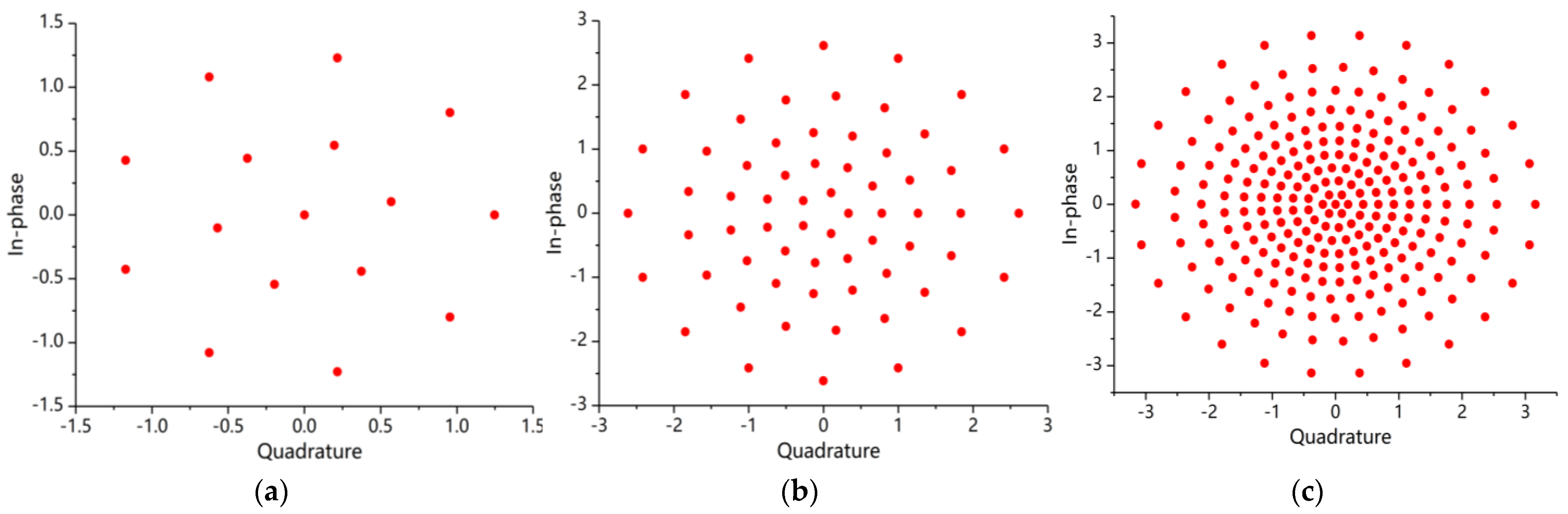
2.1. Geometric Shaping Based on Iterative Polar Modulation

Geometric shaping could achieve shaping gain by optimizing the shape of the high-dimensional signal constellation. Most of the GS algorithms are based on optimizing a specific objective function, such as maximizing mutual information, minimizing BER, or minimizing mean square error (MMSE) to determine the location of constellation points satisfying some conditions.
The IPM modulation format considers the MMSE based on iterative polar quantization procedure [17]. The constellation coordinates determined by a numerical algorithm like Arimoto-Blahut [22] are optimum in the transmission system with significant influence of thermal noise and amplified spontaneous emission noise. The nonuniform iterative polar quantization considers implementing MMSE in two dimensions, including scalar nonuniform amplitude ( r ) and scaler uniform phase quantization ( φ ). The calculation formula of MSE in polar quantization consists of two parts, and could be computed as Equation (1).
M S E = D g r a n u l + D o v e r l o a d
where D g r a n u l represents the granulation noise and D o v e r l o a d represents the overload noise. The granulation noise and overload noise are given by Equations (2) and (3).
D g r a n u l = i = 1 L r j = 1 L i θ j ,   i θ j + 1 ,   i r i r i + 1 [ r 2 + m i 2 2 r m i c o s ( φ φ j , i ) ] · p r ( r , φ ) d r d φ
D o v e r l o a d = r L r + 1 ( r m L r ) 2 p r ( r ) d r
where L i is the number of constellation points on i -th circle; L r is the number of circles; θ j , i is the phase of j -th points on i -th circle; p r ( r ) represents the source of probability density function (PDF). m i is the optimum radius of i -th circle. The optimum number of constellation points of i -th circle is determined by using Lagrange multiplier method to implement MMSE. Accordingly, we have
L i = m i 2 r i r i + 1 p r ( r ) d r 3 / [ i = 2 L r 1 M m i 2 r i r i + 1 p r ( r ) d r 3 ] ;   i = 1 , 2 , L r
As for PDF function of the optimum source, we consider the case of Gaussian distribution, that is
p r ( r ) = 1 2 π σ 2 · exp [ r 2 σ 2 ]
We assumed the partial derivatives to m i and r , respectively, of Equations (2) and (3) are equal to zero, then the optimum radius is given by
m i = [ 2 sin ( Δ θ i / 2 ) r i r i + 1 r p ( r ) d r ] / [ Δ θ i r i r i + 1 p ( r ) d r ] ;   Δ θ i = 2 π / L i ;   i = 1 , 2 , L r
Repeat calculating Equations (4) and (5) until these equations satisfied the following limits of integration determined by Equation (7).
r i = [ π ( m i 2 m i 1 2   ) ] / [ m i L i sin ( Δ θ i / 2 ) m i 1 L i 1 sin ( Δ θ i 1 / 2 ) ] ;   i = 1 , 2 , L r
We could obtain the optimum IPM constellation coordinates using the above Equations (2)–(7). In this paper, three kinds of constellations are generated based on nonuniform iterative polar quantization; the orders of these constellations M are equal to 16, 64, 256, respectively. The relevant constellation is shown in Figure 1, which is consistent with [17,18,19,20]. The IPM constellations show that it is a kind of circle modulation method. Still, the performance is better than circle QAM (CQAM) because of its MMSE and larger channel capacity, especially in the IPM-256. We find out that there is a point at the origin of the coordinate axis in constellations of IPM-16 and IPM-256, respectively, as shown in Figure 1a,c, respectively, which makes it dramatically reduce the average transmission power, which could be called centered-IPM (CIPM).

2.2. K-means Cluster Algorithm at the Receiving End of Data Center

IPM signals are impacted by ASE, fiber dispersion, and other phase noise distortions while they are transmitted from one DC to another. The nonlinear phase noise caused by the Kerr effect will dominate the modulated signal when OSNR is high sufficient. Kerr effect is an electro-optic effect, which indicated that the refractive index is proportional to the square of the applied electric field. Since the refractive index is nonlinear, as the electric field intensity varies in the optical fiber, the refractive index fluctuates, and the signal phase shifts as well, resulting in nonlinear phase noise [23,24,25]. To simulate the nonlinear phase noise generated by the Kerr effect during optical pulse propagation, the Generalized Nonlinear Schrodinger Equation (GNLSE) can be used as the mathematical modeling to describe the process of optical pulse propagation equation [26]. GNLSE, on the other hand, cannot provide an analytical solution for any input light pulse. As a consequence, a numerical method called Split-Step Fourier Transform (SSFT) should be employed to model the propagation of light pulses in a single-mode fiber (SMF) [27]. Accordingly, the essential DSP module is required to recover optical signals at the receiving end of the data center. In response to the frequency offset generated by laser and phase rotation caused by nonlinear phase noise (NLPN), the most common use recovery algorithm is BPS. However, the complexity of BPS grew dramatically as the modulation order increased. Additionally, the BPS algorithm could only compensate ( π / 4 , π / 4 ) phase shift of the range, which is clearly insufficient when there is a factor of frequency offset.
K-means cluster algorithm is an unsupervised learning, which will classify comparable objects into the same cluster. It has the advantages of low complexity, easy implementation, and fast convergence. Its good classification characteristics could be employed to demodulate optical signals that have been greatly affected by NLPN and avoid using BPS algorithm with high complexity. The principle of K-means is mainly to figure out the associated centroid according to the sum of minimum Euclidean distance. The specific procedure of K-means is as follows. Firstly, randomly choose K points as the initial centroids; we set the initial centroids here as the coordinates of the transmission constellation to make the algorithm rapidly converge to the optimal. Then calculate the Euclidean distance between each point and K initial centroids, and assign which clusters the point belongs to. After resetting the locations of the centroid, repeat the above steps until the centroid will not change.
As an example, the transmitting and receiving procedure for 64-QAM is as follows. The bit stream to be transmitted is modulated into optical 64-QAM signal at the transmitter, and then the numerical solution of GNLSE using SSFT algorithm to simulate the optical pulse propagation in SMF is calculated. N symbols affected by dispersion and NLPN are received at the receiving end and classified using the principle of the above-mentioned K-means. The acquired centroid is one-to-one corresponding to the points of the ideal 64-QAM constellation to complete the demodulation. Figure 2 shows the cluster classification result after deploying the K-means algorithm to 64-QAM; it is evident that even if the optical signal phase rotated seriously, the algorithm could still classify and demodulate constellation points more accurately.

3. Simulation System and Results Discussion

3.1. The Establishment of the Simulation System

To verify the performance of the K-means cluster algorithm applied for the IPM modulation format scheme, the simulation system of a single carrier system for the data center interconnection network was established, as shown in Figure 3. Additionally, the parameters of the system are listed in Table 1. At the transmitter, the iterative polar quantization procedure was run to generate the transmitted initially constellations. We generate three constellations here, and the order of these constellations M is equal to 16, 64, 256, respectively. Random pseudo-random binary sequences (PRBS) are generated in MATLAB and sent to the modulator to realize IPM modulation. The modulated signals are shaped by root raised cosine filter, which roll-off factor is equal to 0.25. After pulse shaping, signals are split up into two streams, amplified by electrical amplifiers (EA), and sent to one of the branches of Mach-Zehnder Modulator (MZM). Another branch is driven by External Cavity Laser (ECL), which operates at 1550 nm and its linewidth is 0.1 MHz. Polarization beam splitter (PBS) divide the optical source into two orthogonal polarization beams. Those two orthogonal polarization beams and two streams of data signals interact on MZMs to produce the modulated optical signals combined as optical wave by polarization beam combiner (PBC). Multi-span fiber link consists of recirculation loop, single-mode (SMF) fiber with a length of 100 km, and erbium-doped fiber amplifier (EDFA) with the gain of 20 dB. The main parameters of SMF are chromatic dispersion (CD), attenuation, and nonlinear coefficient, which is equal to 20   ps / ( nm · km ) , 0.2   dB / km , and 1.3   ( W · km ) 1 , respectively. At the receiving end, an optical source generated by another ECL drives the balanced photodetector (PD) after 90 ° hybrid to complete the process of coherent receiving.
The primary affection influence by SMF in a single carrier system is chromatic dispersion and self-phase modulation. Therefore, we need the offline DSP module to recover signals and calculate the BER. The process of DSP is shown in the block diagram at the bottom of Figure 3, which consists of normalization using Gram-Schmidt orthogonalizing process (GSOP), clock recovery using Gardner algorithm, CD compensation, adaptive equalization using constant modulus algorithm (CMA), and phase recovery using BPS or K-means. The recovery signals are demodulated, and then the MI and BER of the transmission are acquired.

3.2. Results and Discussion

To study the performance of channel capacity of different orders of IPM and QAM modulation format, we quantify it by using the physical amount of mutual information. MI versus SNR of different modulation formats after 100 km transmission is shown in Figure 4a. The line with black diamonds is the Shannon capacity. We can find out that MI in IPM outperforms QAM modulation. Moreover, the larger the modulation order is, the closer the distance IPM is to the Shannon Capacity, especially in IPM-256, the purple line in Figure 4a. The MI versus recirculation loops are shown in Figure 4b. We consider the range of the loop is 1 to 10, length of each loop is 100 km. The results show that when employing IPM-16 and QAM 16, the MI is almost the same at loop = 1 and 2. When transmission distance is small, the nonlinear effect is not accumulated too much; when increasing the loop, the MI of IPM-16 is larger than QAM-16, which indicates that IPM-16 could carry more information. When M = 64, the capacity of IPM outperforms QAM even at the larger loop. It indicates that the average power of IPM-64 has a much lower value and has good tolerance to the dispersion, nonlinear effect, and other noises of SMF. When M = 256, the MI of IPM outperforms QAM at loop = 1 to 4; the performance of IPM is not better than QAM when loop > 4. However, as we all know, the distance between DC is usually no more than 100 km. Therefore, the IPM-256 is also suitable for the data center interconnection network.
The fiber channel model can be represented as a linear dispersion noise, additive white Gaussian noise (AWGN) and nonlinear phase noise channel [28,29]. The iterative polar quantization process considers AWGN, such as thermal and ASE noise, rendering the position distribution of constellation points is more subject to the channel characteristics. Hence, the MI can reach its maximum value and the geometric shaping gain is realized. The aforementioned are the major reasons which explain how the suggested technique can effectively narrow the gap with the Shannon limit.
We evaluate the BER performance of IPM-16 and QAM-16 with K-means or BPS in different SNR ranges at loop = 5, as shown in Figure 5a, and the recovery constellations SNR = 16 dB are shown in Figure 5b. The BER decreases as the SNR increases, and it is evident that IPM-16 with K-means algorithm outperforms IPM without K-means and QAM-16. The hard-decision FEC (HD-FEC) threshold is 3.8 × 10 3 , which is mainly used to evaluate the BER performance. Specifically, when SNR is small, the performance of these three schemes is approximately equal. Even the performance of QAM-16 is better than IPM at SNR = 10 to 13. With the increase in SNR, the advantages of the IPM scheme gradually appear. It is clear that IPM with K-means reach the HD-FEC threshold at SNR = 16, while the SNR of reaching the threshold of IPM without K-means and QAM-16 is 16.9 dB, 17.7 dB, respectively. Therefore, the gain of proposed schemes is 0.9 dB, 1.7 dB compared with IPM-16 without K-means cluster algorithm and QAM-16. In the diagram of recovery constellations, the black cross is the centroid locations after a serious iteration, and the centroid could provide a reference for subsequent demodulation.
To study the BER performance of IPM-64 and QAM-64, we draw the curves of BER versus SNR, as shown in Figure 6a. The BER gradually decreases as the SNR increases, and there is a positive correlation between BER and SNR. Additionally, it could be seen that the proposed scheme is superior to IPM-64 without K-means and QAM-64 throughout the entire range of SNR. The proposed scheme reaches the threshold of HD-FEC at SNR = 23.7 dB, while the IPM-64 without K-means cluster algorithm is at 24 dB and QAM-64 is 24.8 dB. The gap between the proposed scheme and the other two schemes is 0.3 dB, 1.1 dB, respectively. It is worth observing from the diagram of the recovery constellation that the points in the corner of QAM-64 mix together and are difficult to distinguish, while the outermost constellation points of IPM have higher discrimination, which indicates that IPM has good robustness to phase noise caused by self-phase modulation.
Figure 7a shows the BER performance of the proposed scheme, IPM-256 without K-means and QAM-256 when loop = 1. We could observe that when SNR = 28 dB, the BER performance of QAM-256 is superior to IPM, yet not as good as the proposed scheme. When SNR > 28.8 dB, the IPM-256 without K-means has a lower BER. For comparison, our proposed scheme acquires 0.4 dB and 0.8 dB, respectively, at the HD-FEC threshold, compared with IPM-256 without K-means and QAM-256. The results fully show that although IPM-256 is not as good as QAM-256 in resisting the influence of nonlinear effect, the system’s tolerance to nonlinear effect is improved after the application of the K-means algorithm.
Due to the involvement of NLPN and the centroid judgement problem, the signal points are excessively divergent when the algorithm converges. Consequently, the BER performance is worse than the IPM employing BPS in the initial SNR range. When employing the K-means algorithm, the SNR of the IPM scheme at HD-FEC threshold is improved dramatically compared to the other two approaches, as shown by Table 2. K-means algorithm can directly process the constellation with phase noise according to the minimum Euclidean distance criterion which will bring classification gain to system. We firstly assign M (depending on the modulation order) initial centroid positions before running the K-means algorithm and generally use the coordinates of the constellation points of the ideal constellation as the initial centroid so that the K-means algorithm can converge quickly. The new centroid of each symbol is determined by calculating the Euclidean distance between the received N symbols with phase noise and M original centroids. Then, the new centroid location coordinates are obtained based on the current constellation point clustering. Repeat the procedure above until the algorithm converges and the final centroid location is the optimum constellation point position with phase offset. Finally, each computed centroid matches the initial ideal constellation point one by one, completing the demodulation step. In contrast, BPS procedure should recover the constellation to standard firstly before demodulating it. The recovery mistake may occur if the constellation was impacted by sufficient phase noise. That is the main reason why the proposed scheme has better BER performance than other schemes. Simultaneously, the proposed technique diminishes the computing complexity by avoiding the phase recovery process.

4. Potential Application Scope

The existing OIN has a more complex network structure and network equipment, which generally complete the scheduling and management of network resources by the software defined network (SDN). The proposed scheme provides a more efficient and adaptive modulation and demodulation algorithm for SDN. SDN controller dynamically adjusts network rate, modulation order and other parameters according to the current network link characteristics and quality of service (QoS), controls the data exchange between switches, and runs network services more effectively and meets dynamic business needs. Meanwhile, the implementation does not need the corresponding demodulation and DSP module, which has lower hardware complexity and can effectively save the cost in OIN deployment. The K-means algorithm used by the receiver is also apt to integrate with SDN, which provides theoretical support for two-tier OIN.
In addition, we all know that the average communication distance between data centers in the same city, especially disaster-tolerant backup data center, is about 60 km, and the longest distance does not exceed 200 km. However, we simulated the MI of each scheme under different loops in Section 3. The maximum loop is equal to 10, reaching 1000 km. At the same time, the proposed scheme shows better BER performance when the modulation formats are 16-IPM and 64-IPM and the simulated transmission distance is 500 km. Since the simulated transmission distance exceeds the actual distance between data centers, and the proposed scheme has better performance, which jointly decide that it can be used not only for OINs, but also for any high-speed and long-distance optical fiber communication system.

5. Conclusions

In conclusion, the state-of-the-art scheme that applied K-means cluster algorithm in geometric shaping based on iterative polar modulation has been proposed, which could be employed in OINs. Even if the transmission distance is sufficient, the proposed scheme could perform better when K-means cluster algorithm in IPM is used, which opens up new applications for it in high-speed, long-distance optical fiber communication systems. We establish a 60 Gbps coherent optical transmission simulation system to verify the performance of our proposal. In terms of mutual information, whether in long/short-distance transmission, IPM could provide a large capacity for the transmission system. For the BER performance, the scheme of IPM-16 with K-means achieves 0.9 dB and 1.7 dB, respectively, compared with IPM-16 without K-means and QAM-16; the scheme of IPM-64 with K-means achieves 0.3 dB and 1.1 dB, respectively, compared with IPM without K-means and QAM 64; the scheme of IPM-256 achieves 0.4 dB, and 0.8 dB, respectively, compared with IPM 256 without K-means and QAM-256. The scheme of IPM with K-means is superior to the other two schemes, which behave as strong robustness to NLPN, according to the aforementioned results, whether in terms of BER or channel capacity. We consider that our proposed scheme will provide a new idea for developing transmission technology of inter-data center optical interconnection networks.

Author Contributions

Conceptualization, X.S. and Q.Z.; methodology, X.S. and Q.Z.; software, X.S. and Z.J.; validation, X.S., R.G. and D.G.; formal analysis, X.S. and Z.J.; investigation, D.G.; resources, Q.Z.; data curation, X.S. and Q.Z.; writing—original draft preparation, X.S.; writing—review and editing, X.S.; visualization, R.G.; supervision, Q.Z. and D.G.; project administration, X.X.; funding acquisition, Q.Z. and X.X. All authors have read and agreed to the published version of the manuscript.

Funding

This research was funded by National Key Research and Development Project of China, under Grant 2019YFB1803701, in part by the National Natural Science Foundation of China under Grant 61835002, 61727817.

Informed Consent Statement

Informed consent was obtained from all subjects involved in the study.

Conflicts of Interest

The authors declare no conflict of interest.

References

  1. Wang, F.; Liu, B. Demonstration of SDN-Enabled Hybrid Polling Algorithm for Packet Contention Resolution in Optical Data Center Network. J. Lightwave Technol. 2020, 38, 3296–3304. [Google Scholar] [CrossRef]
  2. Hu, X.; Sun, Y. A Deep Reinforcement Learning-Based Power Resource Management for Fuel Cell Powered Data Centers. Electronics 2020, 9, 2054. [Google Scholar] [CrossRef]
  3. Chen, B.; Alvarado, A. Analysis and Experimental Demonstration of Orthant-Symmetric Four-Dimensional 7 bit/4D-Sym Modulation for Optical Fiber Communication. J. Lightwave Technol. 2021, 39, 2737–2753. [Google Scholar] [CrossRef]
  4. Dong, Z.; Chen, Y. DMT Transmission in Short-Reach Optical Interconnection Employing a Novel Bit-Class Probabilistic Shaping Scheme. J. Lightwave Technol. 2021, 39, 98–104. [Google Scholar] [CrossRef]
  5. Yuan, H.; Furdek, M. Space-Division Multiplexing in Data Center Networks: On Multi-Core Fiber Solutions and Crosstalk-Suppressed Resource Allocation. J. Opt. Commun. Netw. 2018, 10, 272–288. [Google Scholar] [CrossRef]
  6. Miguel, I.O.; Zuo, T. Multiband Carrierless Amplitude Phase Modulation for High Capacity Optical Data Links. J. Lightwave Technol. 2014, 32, 798–804. [Google Scholar]
  7. Nebojša, S.; Cristian, P. 4D PAM-7 Trellis Coded Modulation for Data Centers. IEEE Photonics Technol. Lett. 2019, 31, 369–372. [Google Scholar]
  8. Julian, R.; Tobias, F. Experimental Comparison of Probabilistic Shaping Methods for Unrepeated Fiber Transmission. J. Lightwave Technol. 2017, 35, 4871–4878. [Google Scholar]
  9. Tobias, F.; Georg, B. LDPC Coded Modulation with Probabilistic Shaping for Optical Fiber Systems. In Proceedings of the 2015 Optical Fiber Communication Conference, Los Angles, CA, USA, 24–26 March 2015; pp. 1–3. [Google Scholar]
  10. Fabian, S.; Georg, B. Protograph-Based LDPC Code Design for Shaped Bit-Metric Decoding. IEEE J. Sel. Areas Commun. 2016, 34, 397–407. [Google Scholar]
  11. Wilfried, I.; Fred, B. Field Trial of a 1 Tb/s Super-Channel Network Using Probabilistically Shaped Constellations. J. Lightwave Technol. 2017, 35, 1399–1406. [Google Scholar]
  12. Georg, B.; Fabian, S. Bandwidth Efficient and Rate-Matched Low-Density Parity-Check Coded Modulation. IEEE Trans. Commun. 2015, 63, 4651–4665. [Google Scholar]
  13. Patrick, S.; Georg, B. Constant Composition Distribution Matching. IEEE Trans. Inf. Theory 2016, 62, 430–434. [Google Scholar]
  14. Fabian, S.; Georg, B. Bit-Metric Decoding of Non-Binary LDPC Codes With Probabilistic Amplitude Shaping. IEEE Commun. Lett. 2018, 22, 2210–2213. [Google Scholar]
  15. Ding, J.; Zhang, J. Comparison of Geometrically Shaped 32-QAM and Probabilistically Shaped 32-QAM in a Bandwidth-Limited IM-DD System. J. Lightwave Technol. 2020, 38, 4352–4358. [Google Scholar] [CrossRef]
  16. Fanny, J.; Tobias, A.E. Experimental Comparison of 64-QAM and Combined Geometric-Probabilistic Shaped 64-QAM. In Proceedings of the 2017 European Conference on Optical Communication (ECOC), Gothenburg, Sweden, 17–21 September 2017; pp. 1–3. [Google Scholar]
  17. Fanny, J.; Tobias, A.E. Design of signal constellations for Gaussian channel by using iterative polar quantization. In Proceedings of the MELECON ‘98. 9th Mediterranean Electrotechnical Conference Proceedings, Tel-Aviv, Israel, 18–20 May 1998; pp. 866–869. [Google Scholar]
  18. Ivan, B.D.; Tao, L. Optimum signal constellation design for ultra-high-speed optical transport networks. In Proceedings of the 2012 14th International Conference on Transparent Optical Networks (ICTON), Coventry, UK, 2–5 July 2012; pp. 1–7. [Google Scholar]
  19. Ivan, B.D.; Hussam, G.B. Coded polarization-multiplexed iterative polar modulation (PM-IPM) for beyond 400 Gb/s serial optical transmission. In Proceedings of the 2010 Conference on Optical Fiber Communication (OFC/NFOEC), San Diego, CA, USA, 21–25 March 2010; pp. 1–3. [Google Scholar]
  20. Liu, X.; Chandrasekhar, S. Generation and FEC-decoding of a 231.5-Gb/s PDM-OFDM signal with 256-iterative-polar-modulation achieving 11.15-b/s/Hz intrachannel spectral efficiency and 800-km reach. In Proceedings of the 2012 Conference on Optical Fiber Communication (OFC/NFOEC), Los Angles, CA, USA, 4–8 March 2012; pp. 1–3. [Google Scholar]
  21. Wang, X.; Zhang, Q. Robust weighted K-means clustering algorithm for a probabilistic-shaped 64QAM coherent optical communication system. Opt. Express 2019, 27, 37601–37613. [Google Scholar] [CrossRef]
  22. Jurgensen, H. A note on the Arimoto-Blahut algorithm for computing the capacity of discrete memoryless channels. IEEE Trans. Inf. Theory 1984, 30, 376–377. [Google Scholar] [CrossRef]
  23. Kikuchi, K. Enhancement of optical-amplifier noise by nonlinear refractive index and group-velocity dispersion of optical fibers. IEEE Photonics Technol. Lett. 1993, 5, 221–223. [Google Scholar] [CrossRef]
  24. Jiang, L.; Yan, L. K-Nearest Neighbor Detector for Enhancing Performance of Optical Phase Conjugation System in the Presence of Nonlinear Phase Noise. IEEE Photonics J. 2018, 10, 7201408. [Google Scholar] [CrossRef]
  25. Saavedra, G.; Tan, M. Experimental Analysis of Nonlinear Impairments in Fibre Optic Transmission Systems up to 7.3 THz. J. Lightwave Technol. 2017, 35, 4809–4816. [Google Scholar] [CrossRef] [Green Version]
  26. Chen, S.S.; Tian, B.; Sun, Y. Generalized Darboux Transformations, Rogue Waves, and Modulation Instability for the Coherently Coupled Nonlinear Schrödinger Equations in Nonlinear Optics. Ann. Phys. 2019. [Google Scholar] [CrossRef]
  27. Gaiarin, S.; Daros, F.; Jones, R.T. End-to-End Optimization of Coherent Optical Communications Over the Split-Step Fourier Method Guided by the Nonlinear Fourier Transform Theory. J. Lightwave Technol. 2020, 99, 418–428. [Google Scholar] [CrossRef]
  28. Beygi, L.; Agrell, E.; Johannisson, P. A Discrete-Time Model for Uncompensated Single-Channel Fiber-Optical Links. IEEE Trans. Commun. 2012, 60, 3440–3450. [Google Scholar] [CrossRef] [Green Version]
  29. Carena, A.; Curri, V.; Bosco, G. Modeling of the Impact of Nonlinear Propagation Effects in Uncompensated Optical Coherent Transmission Links. J. Lightwave Technol. 2012, 30, 1524–1539. [Google Scholar] [CrossRef]
Figure 1. Different orders of constellation based on IPM (a) M = 16; (b) M = 64; (c) M = 256.
Electronics 10 02417 g001
Figure 2. The cluster classification result after employing K-means algorithm to 64QAM; black intersections: ideal constellation points under impacting by NLPN (associated centroids); colored dots: the signals in the cluster associated with the nearest black intersections.
Electronics 10 02417 g002
Figure 3. Simulation setup of a single carrier system for the data center interconnection network.
Electronics 10 02417 g003
Figure 4. (a) MI versus SNR of different modulation format; (b) MI versus Loop.
Electronics 10 02417 g004
Figure 5. (a) BER versus SNR at loop = 5; (b) recovery constellation at SNR = 16 dB; black intersections: ideal constellation points under impacting by NLPN (associated centroids); colored dots: the signals in the cluster associated with the nearest black intersections.
Electronics 10 02417 g005
Figure 6. (a) BER versus SNR at loop = 5; (b) recovery constellation at SNR = 22 dB; black intersections: ideal constellation points under impacting by NLPN (associated centroids); colored dots: the signals in the cluster associated with the nearest black intersections.
Electronics 10 02417 g006
Figure 7. (a) BER versus SNR at loop = 1; (b) recovery constellation at SNR = 28 dB; black intersections: ideal constellation points under impacting by NLPN (associated centroids); colored dots: the signals in the cluster associated with the nearest black intersections.
Electronics 10 02417 g007
Table 1. The parameters of simulation system.
SymbolDescriptionNormal Value
N Number of symbols105
R Transmission bit rate60 Gbit/s
r Roll-off factor0.25
λWavelength1550 nm
Δ v Laser linewidth0.1 Mhz
γ Nonlinear coefficient 1.3   ( W · km ) 1
D Chromatic dispersion 20   ps / ( nm · km )
α Attenuation0.2 dB/km
G EDFA gain20 dB
L o o p Number of spans1–10
L Span length100 km
M Order of constellation16, 64, 256
Table 2. SNR of different approaches at HD-FEC threshold.
Modulation OrderIPM Using K-meansIPM Using BPSQAM Using BPS
1616.0 dB16.9 dB17.7 dB
6423.7 dB24 dB24.8 dB
25628.6 dB29 dB29.4 dB
Publisher’s Note: MDPI stays neutral with regard to jurisdictional claims in published maps and institutional affiliations.

