Review

Supercapacitor-Assisted Techniques and Supercapacitor-Assisted Loss Management Concept: New Design Approaches to Change the Roadmap of Power Conversion Systems

by
Nihal Kularatna
1,
Kasun Subasinghage
2,*,
Kosala Gunawardane
3,
Dilini Jayananda
1 and
Thilanga Ariyarathna
1
1
School of Engineering, University of Waikato, Private Bag 3105, Hamilton 3240, New Zealand
2
Department of Materials and Mechanical Technology, Faculty of Technology, University of Sri Jayewardenepura, Homagama 10200, Sri Lanka
3
Department of Electrical and Electronic Engineering, Auckland University of Technology, Auckland 1142, New Zealand
*
Author to whom correspondence should be addressed.
Electronics 2021, 10(14), 1697; https://doi.org/10.3390/electronics10141697
Submission received: 5 June 2021 / Revised: 2 July 2021 / Accepted: 6 July 2021 / Published: 15 July 2021
(This article belongs to the Special Issue Supercapacitor Applications)

Abstract

:
All electrical and electronic devices require access to a suitable energy source. In a portable electronic product, such as a cell phone, an energy storage unit drives a complex array of power conversion stages to generate multiple DC voltage rails required. To optimize the overall end-to-end efficiency, these internal power conversions should waste minimal energy and deliver more to the electronic modules. Capacitors are one of the main component families used in electronics, to store and deliver electric charges. Supercapacitors, so called because they provide over a million-fold increase in capacitance relative to a traditional capacitor of the same volume, are enabling a paradigm shift in the design of power electronic converter circuits. Here we show that supercapacitors could function as a lossless voltage-dropping element in the power conversion stages, thereby significantly increasing the power conversion stage efficiency. This approach has numerous secondary benefits: it improves continuity of the supply, suppresses voltage surges, allows the voltage regulation to be electromagnetically silent, and simplifies the design of voltage regulators. The use of supercapacitors allows the development of a novel loss-circumvention theory with applicability to a wide range of supercapacitor-assisted (SCA) techniques. These include low-dropout regulators, transient surge absorbers, LED lighting for DC microgrids, and rapid energy transfer for water heating.

1. Introduction

Electrical circuits primarily carry three types of components, namely resistors, capacitors, and inductors. In electronic circuits, semiconductor devices such as diodes and transistors, in general act as non-linear devices, combined with parasitic capacitances and inductive elements. Commonly used capacitors in electronic circuits are used for smoothing, buffering, filtering, bypassing, and DC blocking. They usually come in capacitance values ranging from 10 pF to 100,000 µF, with rated DC voltages in the range of 10 V to over 5 kV, and their energy storage capability could vary from few nJ to few 100 J. During the past two decades, a new family of capacitors known as supercapacitors (SCs) entered the electronic component world to fill the gap between batteries and classical capacitors, allowing new applications [1].
A supercapacitor can be considered to have one million times larger capacitance than a normal electrolytic or a film capacitor of the same canister size and they achieve energy capabilities in the range of 100 J to over 100 KJ. They have power densities up to 32 kW/kg, maximum energy density up to 20 Wh/kg, and low equivalent series resistance (ESR) values below 100 mΩ [2,3]. Commercially available SC families have capacitance values from 1 F to 70,000 F with DC voltage ratings in the range of 2.5 V to 5.0 V. Table 1 summarizes the comparison of characteristics of supercapacitors versus batteries and conventional capacitors which supports the selection of supercapacitors as an ideal candidate for various power electronic applications. Compared to batteries, where the internal resistance keeps increasing with the discharge, SCs can deliver very high power density in an affordable, compact package due to very low and relatively constant ESR [4,5,6]. SCs are free from problems associated with batteries, such as limited cycle life, cold intolerance, and critical charging rates [4].
The first type of SC family is symmetrical electric double-layer capacitors (EDLC), which are based on activated carbon electrodes with different types of electrolytes [12,13]. The next type is hybrid devices, where one electrode is activated carbon, and the other is similar to an electrode in Li-ion batteries. The third type is battery-capacitors, based on the concept of pseudocapacitance [14], with a significantly lower cycle life compared to symmetrical types, have an energy density close to lead-acid batteries. Figure 1 depicts a representative electro-chemistry of these three types and Table 2 summarizes their basic characteristics.
Although the major limitation of SCs is their low voltage rating (typically less than 5 V), device manufacturers now supply supercapacitor modules (SCMs) with different voltage ratings up to several hundred volts, making SCMs suitable for a wide variety of energy storage and power conversion applications [5]. These SCMs are made by connecting large numbers of SCs in series strings (and sometimes combining multiple strings in parallel) to achieve overall higher voltage ratings with the penalty of rising in the total equivalent series resistance [21,22,23]. As the capacitance of a commercial SC deviates about 20% from its nominal value, the total voltage across the SC bank will not be equally distributed among the single SC cells connected in series. This method leads to over-voltage conditions appearing in one or more SC cells, resulting in individual cells being overcharged. Therefore, active or passive voltage balancing circuits are employed in SC banks to regulate the individual cell voltage. To improve the rated voltage of SCs while achieving increased capacitance, hybrid SCs have been developed by combining an anode of tantalum electrolytic capacitors with a cathode of electrochemical capacitors [24]. These hybrid SCMs meet the requirements for larger capacitance while maintaining a high working voltage of about 100 V and a smaller internal resistance and size [22].
This review article is to present a unique new theoretical concept and set of applications now known as supercapacitor assisted (SCA) techniques, which could create a paradigm shift in power converters, protection systems, and renewable energy-based systems. It is important to highlight here that the wider research team started treating the case of an ideal SC as a lossless voltage dropper based on the simple relationship of small voltage change across the device which changes very slowly over time, due to several orders larger capacitance. Their first successful SCA technique, now known as the supercapacitor-assisted low dropout (SCALDO) regulator (which will be discussed later), was a linear DC-DC converter, and they proposed placing an SC in series with the linear converter to make use of the voltage difference across the SC (which changes slowly with time) to reduce the loss in the series pass device and increase the converter’s efficiency [25].
This paper is organized as follows: Different applications of SCs are summarized in Section 2 considering traditional, and commercial applications. Section 3 summarizes the properties of SC-based long-time constant circuits. Section 4 introduces the theory of Supercapacitor-Assisted Loss Management (SCALoM) and Section 5 discusses the real-world implementations based on this theory. Finally, the concluding remarks are presented in Section 6.

2. Conventional Applications of Supercapacitors

In the early stages of the development of SCs, they came with only a few farads of capacitance, with ESR of fractional ohms to several ohms. Their application scope was limited to powering memory modules for short- to medium-term backup [26,27]. With new commercial SC families that entered the market after 2005 with single-cell devices with capacitance over thousands of farads, they were used to hybridize with battery packs to make use of their high power density compared to batteries. Today, these EDLCs have a broad application spectrum, including automotive applications (electric vehicles, hybrid electric vehicles, trolleybuses, trains), biomedical devices, telecommunication devices, uninterrupted power supplies, and volatile memory backups in PCs [27,28]. They are also used in energy harvesting systems, solar arrays, and wind turbines [27,28]. One study mentions that with the increase of energy density of SCs and with the longer cycle life, they are becoming more attractive for wearable applications [29].
In today’s market, SC manufacturers strive to come up with different product scales to match various requirements. For example, Cap-XX (an Australian supercapacitor manufacturer), supplies thin-profile SCs for versatile applications including indoor energy harvesting units, smart meters, cellular phone or digital camera flash systems, wireless sensors, instantaneous power requirements in general packet radio service (GPRS), and transient power requirements in class-D audio amplifiers [30]. Maxwell Technologies (now owned by Tesla) provides higher-capacity single-cell elements up to about 3500 F/3 V, aiming their products at automotive peak power assist, hybrid vehicles, hybrid and plug-in hybrid buses, wind turbine pitch control, onboard and wayside rail, heavy industrial equipment, UPS, telecom systems, and heavy-duty truck engine start [31].
Apart from the standalone applications of SCs, they can be combined with other energy storage devices to increase the performance of different applications. A recent study showed that SCs in conjunction with batteries can be used in mobile applications to extend the battery runtime and improve the short-term energy burst requirements [32]. Several studies have shown that power-sharing between supercapacitors, fuel cells, and batteries can improve the overall system performance [33,34,35]. A study on reduction in battery stresses of a 500 kVA rated UPS using supercapacitors (SCs) aimed at investigating the optimal supercapacitor–battery combination versus SC cost [36]. The possibility of storing transient surges using supercapacitors was investigated in [37]. A dual-input positive buck-boost converter was proposed for integrating piezoelectric energy harvester (PEH) and supercapacitors in [38]. In this study, both sources can feed the load simultaneously or independently, resulting in a reduced component count. Another study proposed a multi-port bidirectional DC-DC converter using EDLCs to control the energy flow of fuel cells, which contributes to the longer operating life of the fuel cell system [39]. In [40], a series or parallel changeover system using a battery with an EDLC was proposed for a small electric vehicle (EV). A 100 kW DC-DC converter was designed in [41] that transfers energy while keeping the galvanic isolation between a 560 V DC rail and two 125 V SC stacks. In one phase of the operation, the SC stacks are charged by a current source, and in the other phase, the stored energy is delivered back by using a step-up DC-DC converter. Another bidirectional DC-DC converter with a supercapacitor DC-link was proposed in [42]. The study in [43] proposed a bidirectional DC-DC converter with EDLCs for a power leveling system targeting irregular power generation such as distributed generation.
One commercial application of supercapacitors was ABB’s flash charging station in a Swiss city, which allowed electric buses to fully charge in less than 10 min. Since bus lines are most active during the day, it also aimed to take advantage of solar energy and store that energy as an electric charge in SCs. The flash charger station flattens out demand by charging supercapacitors over a few minutes while drawing a lower current from the grid. Additionally, recharging of the supercapacitors is timed so that they are left discharged for long periods when the bus service is running at a lower frequency, and this ‘smart’ functionality allows the life of the supercapacitors to be doubled [44].
Another commercial application is the new Lamborghini Sián FKP 37 car. This car has a hybrid architecture that uses a lithium-ion supercapacitor, which is three times more powerful than a battery of the same weight. It is a low-voltage (48 V) system with peak currents of up to 600 A. Powered by this current, the electric motor delivers engine torque directly to the rear wheels, and regenerative braking makes it possible to recharge the lithium-ion supercapacitor. The electrical power flow is symmetrical for the same efficiency during the charge and discharge cycles, without overheating [45].

3. Supercapacitor-Assisted Long-Time Constant Techniques for Non-Conventional Applications

An ideal supercapacitor with near-zero ESR can be used as a theoretically lossless voltage dropper (until the SC blocks the DC path) in circuits. The simple concept of choosing a supercapacitor as the lossless series dropper element is as follows. When an ideal capacitor CSC is charged by a finite current i(t) for a period t2–t1, the voltage change across the capacitor is given by Equation (1).
v = 1 C SC t 1 t 2 i t dt
If the capacitor is very large, as in the case of an SC, the voltage change is minimal during the charging time. Most commercial families of SCs have very low ESR and their very large capacitance allows them to be used as lossless voltage droppers in analog circuits. Applying this unique characteristic of SCs, they are used for long-time constant circuit topologies. Therefore, this paper discusses supercapacitor-based long-time constant circuit topologies that could ultimately lead to changes in the road map of power converter designs.
During the last decade, numerous supercapacitor-assisted (SCA) power converter and protection circuit topologies have already been developed by two research groups in New Zealand. A few examples are SCA low dropout regulator (SCALDO), SCA surge absorber (SCASA), SCA wide input PV inverter (SCAWI-PV Inverter), and SCA light-emitting diodes (SCALED) [46,47,48,49]. Conceptually when an SC is connected in series with a resistive load such as a loaded DC-DC converter, inverter, or an LED bank, it creates a very long-time constant circuit and allows very low-speed switching. The stored energy of the series SC or an array of SCs during the charging phase is released back to the useful load using a discharging loop while maintaining the charge balance of the capacitors [50].
These new SCA topologies were designed based on the Supercapacitor-Assisted Loss Management (SCALoM) theory, which is an extension of the traditional RC circuit, where SCs replace the conventional capacitors to purposely achieve a low-speed circuit [6]. Researchers from other countries apart from the first group have also been active in the development of these SC-assisted slow-time varying topologies [51,52,53].

4. Supercapacitor-Assisted Loss Management (SCALoM) Theory

The SCALoM theory is an extension of the traditional textbook Resistor-Capacitor (RC) circuit theory with the aim of achieving higher charging efficiency in the charging loop using the advantage of the large time constant of a supercapacitor combined with a useful resistive load in the loop. Starting from the traditional RC theory, the fundamental background of this theory is described in three stages (Section 4.1, Section 4.2 and Section 4.3) as follows [54]:

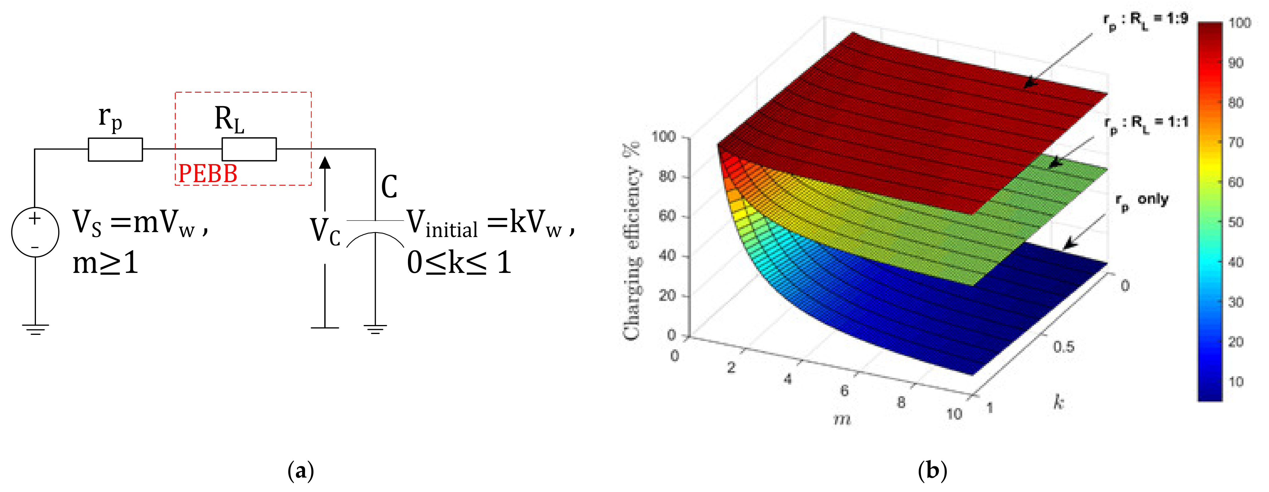
4.1. Adding a Useful Load into Traditional RC Charging Loop

In a simple RC charging circuit as shown in Figure 2a, an uncharged capacitor starting from a zero charge achieves an energy content of 0.5   CV S 2 after about 5 time constants if the input source voltage is VS. During this time, the resistive components (rp: parasitic circuit resistance) in the loop wastes an equal amount of energy irrespective of the value of its resistance, so the charging process is 50% efficient. This energy loss ( E r p ) can be written as in Equation (2).
E r p = 1 2 CV S 2
The simple RC circuit can be modified as shown in Figure 2b by inserting a power electronics building block (PEBB) such as a loaded DC-DC converter, a loaded inverter, or any other “useful” resistive load (RL) (e.g., a heating element) into the loop. When the circuit is modified by inserting RL, total loop resistance becomes (rp + RL) and the wasted energy due to rp is negligible if RL >> rp. Therefore, the energy loss due to rp is now reduced as defined in Equation (3).
E r p = 1 2 CV S 2 r p r p + R L
Then, the overall charging efficiency of the system in Figure 2b can be expressed as:
η = 1 1 2 r p r p + R L 100 %

4.2. Inserting a Partially Charged Supercapacitor into the Charging Loop

Figure 3 depicts the second modification to the case in Figure 2a by inserting a supercapacitor into the charging loop, with a pre-charge voltage of kVW (where VW is the working voltage, k is a constant: 0 ≤ k ≤ 1), together with the supply voltage increased to Vs = mVw, by a factor of m (m > 1). This improvement in Figure 3a is to accommodate the insertion of a useful load (RL) into the loop later, as shown in Figure 4a.
For calculations, k is defined as the pre-charge factor, and m is defined as the power supply over-voltage factor. This is to take advantage of the high charge/discharge capability of supercapacitors, as well as the very long life cycles of commercial supercapacitors (which are several orders larger than rechargeable batteries) [50,55]. By adding a supercapacitor, the circuit becomes very slow, allowing easier changes from charge to discharge of the capacitor using low-cost, low-speed switches.
In the partially charging curve of the SC displayed in Figure 3b, the capacitor voltage (VC(t)) increases from kVW to VW during the period t1 to t2. The efficiency of the charging under these conditions can be determined as a function of k and m, as shown below.
The increment in stored energy in the supercapacitor ( E C ) between time t1 and t2 is
E C t 1 , t 2 = 1 2 C · V w 2 1 2 C · kV w 2 = 1 2 C · V w 2 1 k 2
The voltage across parasitic resistance ( V r p ) during the SC charging process as per Figure 3a is given in Equation (6).
V r p = mV w   V C t = mV w mV w   1   e t r p C   =   mV w e t r p C
while the energy loss in r p over the time interval t1 to t2 is given by the integral as
E r p t 1 , t 2 = t 1 t 2 i t 2 · r p · dt
where i t 2 · r p = V r p 2 r p = m 2 V w 2 e 2 t r p C r p .
Integrating (7), and substituting leads to
E r p t 1 , t 2 = CV w 2 2 k 2 2 km + 2 m 1
The charging efficiency ( η ) of the partially charging process of SC from t1 to t2 is given by
η = E C E r p + E C · 100 % = 1 k 2 2 m 1 k 100 %   = 1 + k 2 m 100 %
In the limit k → 0 (with no capacitor pre-charge) and m → 1 (no power supply overvoltage factor), the efficiency ( η ) > 1/2, given the standard textbook results according to Figure 2a. Equation (9) shows that the efficiency is enhanced if the capacitor carries a percentage charge—so it is never allowed to fully discharge during a cycle, thus avoiding the large energy losses that accrue when the current is high. The optimum efficiency is achieved when (k, m) is equal to (1:1).

4.3. Combining the Useful Load and the Partially Charged Supercapacitor in the Charging Loop

Figure 4 depicts the overall case with the resistive load, parasitic resistance, and the partially charged supercapacitor working in a very long RC time constant circuit. The charging efficiency defined in Equation (9) can be further improved for the case in Figure 4a as shown below.
The energy consumption of the load resistor ( E R L ) over the time interval t1 to t2 is given by the integral as
E R L t 1 , t 2 = t 1 t 2 i t 2 · R L · dt
Given the case that the energy stored in SC is to be reused in a discharge operation with the energy source disconnected, efficiency the expression of Equation (9) is modified to
η = E C + E R L E C + E R L + E r p
After completing similar simplification steps for Equation (10) as in Equation (8), the efficiency expression of Equation (11) is modified to
η = 1 1 + p p + 1 + k 2 m   ·   100 %
where p = R L / r p and p > 1 .
The derivations of Equation (12) are given in [55]. The trends of Equation (12) are illustrated in Figure 4b, which shows that when the ratio ( p = R L / r p ) becomes larger, the efficiency advantage increases significantly. The middle and upper traces of Figure 4b depict this claim for r p : R L = 1 : 1 and 1 : 9 , respectively.
Given the above case of improving the overall charging efficiency of an RC circuit loop by inserting a useful resistive load, a pre-charged supercapacitor, and an increased power source to suit the overall implementation, loss within the RC loop can be managed effectively to achieve high-efficiency power converters and protection circuits [50]. This is introduced as the SCALoM theory, making use of the basis of Equation (12). In a discharging phase of the circuit, based on low-speed switches inserted into the loop as appropriate, the input power source can be disconnected to drive the load from the stored energy of the SC, while maintaining the energy balance of the supercapacitor. The SCALDO [46] and SCALED techniques [49] are typical application examples of this SCALoM theory.

5. Validity and the Practical Application of the SCALoM Theory

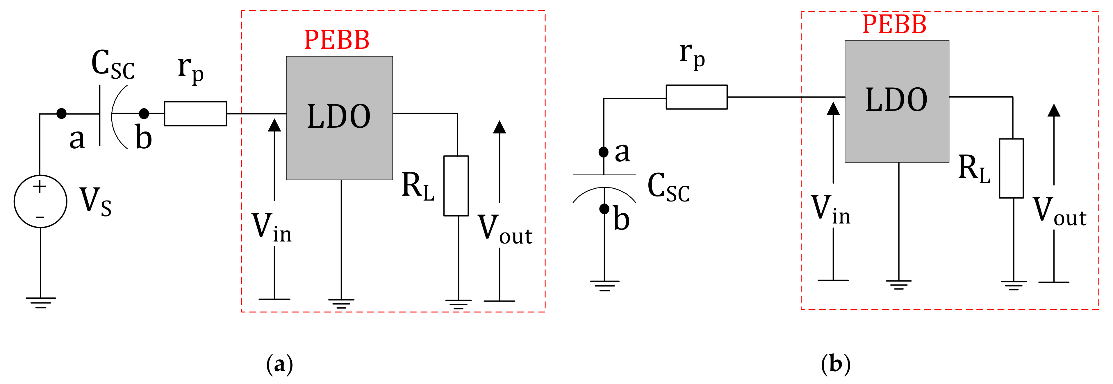
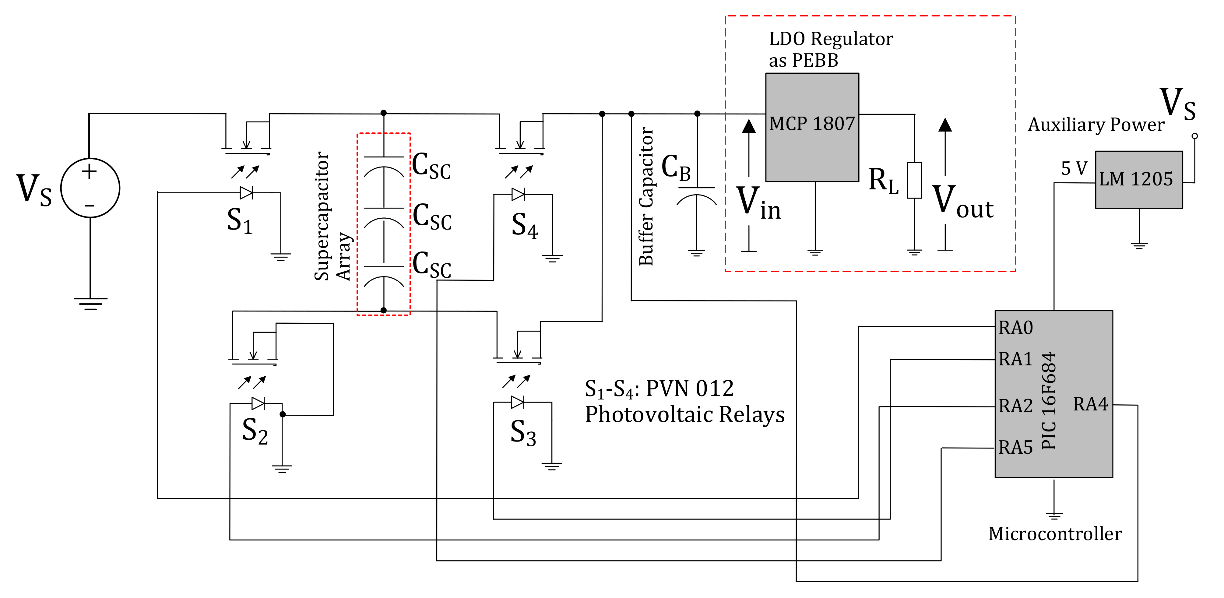
5.1. Supercapacitor-Assisted Low-Dropout (SCALDO) Regulator

The efficiency of a linear regulator is given by the approximate relationship of η = V out V in (where the input voltage is Vin and the output voltage is Vout), assuming the control circuits consume minimal power. Usually, in a linear regulator configuration, most of the energy is dissipated across the internal series pass device. Introducing a voltage dropper in series with the pass element such as an external resistor (RS) shown in Figure 5 will make the dissipation across the pass element lower when the supply increases. Nevertheless, this arrangement has several limitations. First, it will not improve the overall end-to-end efficiency, as the external resistor contributes to energy loss. The second is that the voltage drop across RS depends on the output load current.
An ideal voltage dropper element such as a capacitor or an inductor can be placed across points a and b in Figure 5 as an alternative method without degrading the overall efficiency. Nevertheless, an inductor cannot be placed in the series path, as it defeats the purpose of a constant load current to the regulator. A very large capacitor with near-zero ESR (e.g., a commercial supercapacitor) is a suitable candidate, whereas a smaller capacitor would quickly block the series DC in the circuit. The supercapacitor-assisted low-dropout regulator technique was first developed based on the above principle, and will be discussed below.
Figure 6 is an illustration of the SCALoM theory applied to a linear regulator circuit in which a LDO regulator and its output load are represented by the PEBB. The ESR of the SC, the internal resistance of the voltage source, and other conductive losses represent the total loop parasitic resistance rp. In Figure 6a, the power source, the SC, and the LDO regulator are connected in series in the charging mode. Because of this series connection, the SC acts as a lossless series dropper element between the source and the LDO regulator. Due to this effect, the DC is not blocked, and the LDO regulator keeps the output DC voltage regulated for a finite amount of time. As the SC charges, the input voltage of the LDO regulator decreases. The SC is kept in this position until the input voltage of the LDO regulator falls to its minimum operating voltage (Vmin). When the charging process is completed, the SC is connected in parallel with the LDO regulator by disconnecting the power source, as shown in Figure 6b. The SC is allowed to discharge until the input voltage of the LDO regulator drops back to Vmin. These two operating modes run cyclically while maintaining the charge balance of the SC, and the switching frequency typically varies by fractions of hertz to a few hertz.
Provided that rp is very small compared to RL, the SC is pre-charged to a voltage close to the minimum working voltage of the linear regulator and the control circuit power loss is negligible; this method provides an approximate ETEE of 2 V out V in , which is twice the efficiency of a linear regulator for the same input–output voltage combination. When considering the 12–5 V SCALDO regulator, an ETEE of 83.3% can be achieved with the use of the SC energy circulation technique, compared to the 41.7% ETEE achieved with a 5 V LDO regulator driven by direct 12 V supply [56]. The theoretical and measured efficiencies of this technique are compared with the standalone 5 V LDO regulator in Figure 7 for a range of supply voltages. The SCALDO regulator keeps the same useful characteristics of a linear regulator while having minimal EMI/RFI issues. It is important to highlight here that the SCALDO technique is not a variation of conventional switched capacitor converters for a multitude of valid reasons, as summarized in [57].
Figure 8 depicts an implementation in which four very low-speed switches (S1 to S4) are used at points a and b of Figure 6. These switches are controlled by a low-cost controller such as a microcontroller. A silicon integrated circuit (IC) implementation of the SCALDO technique, which is currently under testing, is shown in Figure 9. In this silicon implementation, analog comparators and digital logic devices replace the external digital processor used for discrete design. It has also been proven that the SCALDO technique does not create any stability issues on the LDO regulator applied [58].
The generalized SCALDO concept is applicable to any step-down linear DC-DC converter [56,59]. The first successful application of the above theory was to extend the ETEE of a linear DC-DC converter by a figure of merit factor of M (M > 1). This technique [46,60] is unique, as it helps to increase the efficiency of a linear regulator by a factor where M = 1 + N for cases in which the input voltage is much greater than the regulated output (e.g., 12–5 V conversion), and M = 1 + 1 N for cases where the input voltage is only slightly higher than the input (e.g., 5–3.3 V conversion), where N indicates the number of supercapacitors required [56]. The SCALDO technique was further extended to a dual-output split-rail version in [61].
Table 3 compares the three traditional converter techniques with the SCALDO technique, which has the following additional advantages.
  • By oversizing the SC, DC-uninterrupted power supply (DC-UPS) capability can be incorporated [62]
  • Significantly low RFI/EMI issues since the SC charge to discharge transition happens at a fractional hertz-order frequency [46,59]
  • Lower component count compared to inductor-based switch-mode converters, which in turn reduces the PCB space requirement [46,63]
During the last 5 years, the SCALDO technique has successfully been extended to several wider applications [61,62,64], showing its versatility, including an ongoing development towards a topology suitable for Google’s new 48 V architecture [64].

5.2. Supercapacitor-Assisted LED (SCALED) Converter

The traditional approach to harvesting renewable energy and coupling it with the AC utility supply is based on a DC-AC converter (inverter) with or without a battery pack. Nevertheless, the use of a battery bank adds environmental concerns in the long run. Several supercapacitor manufacturers, such as Samwha Electric and Kurt Energy, have introduced several new families of hybrid supercapacitors [65,66,67,68] that are close to the energy density of lead-acid batteries. With the availability of these hybrid devices of very large capacitance per cell, in the range of 5000 F to 70,000 F, replacing batteries with SC modules is a reality today, at least for buffering the short-term fluctuations of renewable sources [69,70].
LED lighting is one of the key areas harnessing the benefits of DC microgrid concepts. The supercapacitor-assisted LED lighting (SCALED) converter shown in Figure 10a is an extension of the SCALoM concept in which an RC charging loop is modified with a useful load of LED lamps [49,71]. This circuit has two basic operating phases. In the first phase, switch S1 is closed, and switch S2 is opened. This operation allows the SC to charge in series with the LED load. In the next phase, S1 is opened, S2 is closed, and the DC source is disconnected. The LED load is entirely driven from the stored energy of the SC in this phase. The corresponding voltage waveforms of the load and the SC are depicted in Figure 10b. It should be noted here that the LED lamp used in this concept can operate without the issue of polarity. The switches operate in such a way that neither the LED lamp nor the SC bank are exposed to any unsafe higher DC voltages. The control of the switches is typically performed with the aid of a microcontroller; more implementation details can be found in [49].
The loss management of the SCALED technique with respect to the SCALoM theory is carried out as follows. The LED lamp in Figure 10a acts as the PEBB, which usefully consumes energy while charging the capacitor. If the equivalent DC resistance of the LED lamp (RL) is much larger than the parasitic resistances of the loop (rp) and the capacitor is an adequately sized supercapacitor bank, this represents the simplified basis of the new SCALED technique.
When it comes to real-world application scenarios of the SCALED converter, a PV module replaces the DC source with an open-circuit voltage VOC higher than the nominal voltage of the LED lamp and the SC bank. The SC bank not only acts as an energy storage device, it also acts as a lossless voltage dropper similar to in the SCALDO technique. Since the charging time for the SC bank is longer due to the extra-large capacitance, it is quite easy to operate the switches at low frequency with minimal switching losses. The SCALED converter uses the SCALoM concept with an over-rated voltage source, a pre-charged capacitor, and a useful resistive load. The efficiency of the SCALED converter is typically in the range of 90% to 94% [72].

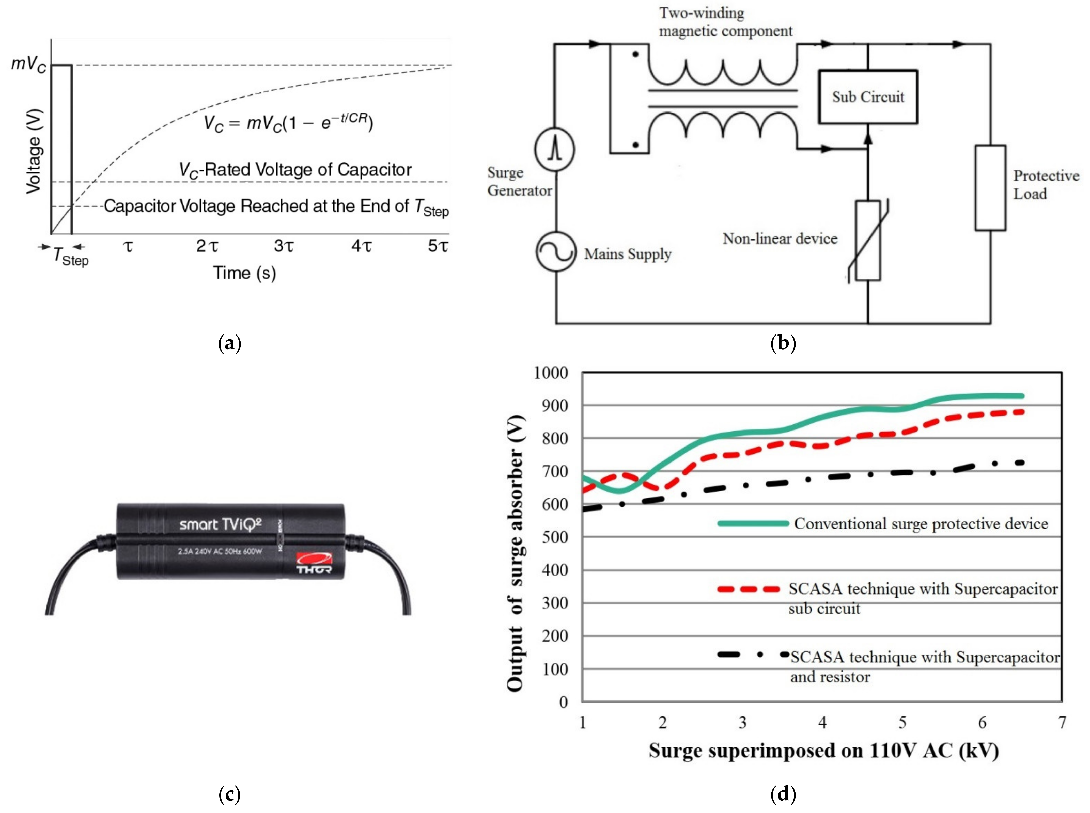
5.3. Supercapacitor-Assisted Surge Absorber (SCASA)

While developing the SCALDO topology, in 2011, the main research team investigated the ability of SCs to safely absorb transient surges defined by standards such as IEEE C62-4X series and presented this technique in an IEEE publication [73]. Motivated by this result, SCALoM theory was successfully extended to another unique power electronics application, namely the SCA surge absorber (SCASA) technique. In this case, an SC is inserted into the RC circuit, creating a large time constant circuit, where loop resistance is used to dissipate the destructive energy in the transient surge superimposed on the incoming power line.
Figure 11a depicts a case in which a significant part of the energy is in a microsecond-order surge, dissipating in the loop resistance, during which time the SC does not charge beyond its rated DC voltage, where the surge voltage is indicated as mVC, which is a multiple of the rated voltage of the capacitor VC. Nevertheless, given the very low DC voltage rating of a commercial SC, and its very low AC impedance at line frequency, the coupled inductor-based circuit shown in Figure 11b was required to achieve a commercially useful circuit. Due to the transformer action of the coupled inductor, when the non-linear device (typically a metal oxide varistor) fires, a transient voltage is induced in the secondary winding, opposing the incoming high-voltage and reducing the surge effect on critical load [74]. The subcircuit in Figure 11b represents several combinations of impedances: (a) SC only, (b) SC with a series resistor, (c) SC with a series inductor, and (d) SC with a series resistor and an inductor.
Figure 11c depicts a commercial version of this patented technique [75], now sold as Smart TVIQ by Thor Technologies, Australia. Compared to traditional surge protectors, in SCASA-based products, the component count is lower and the clamping voltage is much lower, as shown in Figure 11d. The SCASA technique easily satisfies the UL 1449 3rd Edition standard [76].

5.4. Wider Potential SCA Applications in Power Conversion

SCALoM theory has a much wider application scope, and is able to achieve higher efficiency power converters in general. An area under early investigation is focused on the potential application of reduced RC loop charging losses in typical AC-DC converters within computer power supplies, industrially known as silver boxes. Silver box power supplies work seamlessly from about 85 to 260 VAC, allowing them to operate in either 230 V/50 Hz or 120 V/60 Hz utility mains. By dividing the rectifier stage into two identical modules of half power delivery, with suitably switched SC banks could reduce rectifier losses, utilizing this energy recovery concept is currently a work in progress.
SCA-temperature modification apparatus (SCATMA) [77] is a unique SC-based rapid energy delivery system that is designed to overcome the worldwide issue of hot water delay in our domestic faucets [78]. A by-product of the SCATMA technique was a unique fast-charger topology for charging larger SC banks [78].
The SCA-submodule inverter (SCASMI) technique [48,54] is another collaborative research project with the target of achieving high-performance inverters based on the same SCALoM theory, for more effective harnessing of renewable energy. The SCA DC circuit breaker (SCA-DCB) is yet another such development, aimed at solving a major issue faced by the DC Microgrids, recognizing the fundamental issue of a DC loop compared to 50 Hz/60 Hz utility power waveforms, where two zero crossings per AC cycle help in the design of a cost-effective circuit breaker.

6. Conclusions

The SCALoM concept provides a unique new theoretical platform for high-efficiency RFI/EMI-free supercapacitor-based power converters and protection systems to increase the overall energy efficiency of power conversion systems used in portable products and renewable energy converters. Based on this new theory, the several successful applications presented demonstrate clear evidence. SCA techniques offer a unique low-frequency design approach that is emerging for high-efficiency power converters, with added advantages such as the DC-UPS capability within the converter, elimination of RFI/EMI issues typical to high-frequency switching converters, and input range extension. The research team in NZ is keen to develop collaborative research to explore the wider application space of the SCALoM theory.

Author Contributions

Conceptualization, N.K., and K.G.; methodology, K.S.; software, K.S, and T.A.; validation, K.S., D.J. and T.A.; formal analysis, K.S., K.G.; investigation, K.S., D.J., and T.A.; resources, K.S.; data curation, K.S.; writing—original draft preparation, N.K., K.S., K.G., D.J., and T.A.; writing—review and editing, N.K., K.S., K.G.; visualization, K.S.; supervision, N.K., and K.G.; project administration, N.K.; funding acquisition, N.K. Conceptualization and researcher leadership-Nihal Kularatna; Development of SCALDO. All authors have read and agreed to the published version of the manuscript.

Funding

This research was funded by University of Waikato and Auckland University of Technology.

Conflicts of Interest

The authors declare no conflict of interest.

References

  1. Karthikeyan, S.; Narenthiran, B.; Sivanantham, A.; Bhatlu, L.D.; Maridurai, T. Supercapacitor: Evolution and review. Mater. Today Proc. 2021. [Google Scholar] [CrossRef]
  2. Rani, J.R.; Thangavel, R.; Oh, S.I.; Lee, Y.S.; Jang, J.H. An Ultra-High-Energy Density Supercapacitor; Fabrication Based on Thiol-functionalized Graphene Oxide Scrolls. Nanomaterials 2019, 9, 148. [Google Scholar] [CrossRef] [Green Version]
  3. Hunter, C. Supercapacitors Can Challenge Tantalums on ESR; Endeavor business media, LLC: Nashville, TN, USA, 2006. [Google Scholar]
  4. Kim, Y. Ultracapacitor Technology Powers Electronic Circuits. Power Electron. Technol. 2003, 29, 34–39. [Google Scholar]
  5. Kularatna, N. Supercapacitors Improve the Performance of Linear Power-Management Circuits: Unique new design options when capacitance jump from micro-farads to farads with a low equivalent series resistance. IEEE Power Electron. Mag. 2016, 3, 45–59. [Google Scholar] [CrossRef]
  6. Kularatna, N.; Gunawardane, K. Energy Storage Devices for Renewable Energy-Based Systems; Academic Press: London, UK, 2021. [Google Scholar]
  7. Schneuwly, A.; Gallay, R. Properties and Applications of Supercapacitors From the State-of-the-art to Future Trends. In Proceedings of the PCIM 2000, Nuremberg, Germany, 6–8 June 2000. [Google Scholar]
  8. Rafik, F.; Gualous, H.; Gallay, R.; Crausaz, A.; Berthon, A. Frequency, thermal and voltage supercapacitor characterization and modeling. J. Power Sources 2007, 165, 928–934. [Google Scholar] [CrossRef]
  9. BU-410: Charging at High and Low Temperatures. Available online: https://batteryuniversity.com/learn/article/charging_at_high_and_low_temperatures (accessed on 28 May 2021).
  10. Supercapacitor Application Guidelines; Eaton: Cleveland, Ohio, USA, 2017.
  11. muRata Electrical Double Layer Capacitor (EDLC); Murata Manufacturing Co., Ltd: Kyoto, Japan, 2014.
  12. Sarno, M. Chapter 22—Nanotechnology in energy storage: The supercapacitors. In Studies in Surface Science and Catalysis; Basile, A., Centi, G., Falco, M.D., Iaquaniello, G., Eds.; Elsevier: Amsterdam, The Netherlands, 2020; Volume 179, pp. 431–458. [Google Scholar]
  13. Sudhakar, Y.N.; Selvakumar, M.; Bhat, D.K. Chapter 3—Biopolymer Electrolyte for Supercapacitor. In Biopolymer Electrolytes; Sudhakar, Y.N., Selvakumar, M., Bhat, D.K., Eds.; Elsevier: Amsterdam, The Netherlands, 2018; pp. 53–116. [Google Scholar] [CrossRef]
  14. Zhou, L.; Li, C.; Liu, X.; Zhu, Y.; Wu, Y.; van Ree, T. Chapter 7—Metal oxides in supercapacitors. In Metal Oxides in Energy Technologies; Wu, Y., Ed.; Elsevier: Amsterdam, The Netherlands, 2018; pp. 169–203. [Google Scholar] [CrossRef]
  15. Zhou, Z. Modeling and Power Control of a Marine Current Turbine System with Energy Storage Devices. Ph.D. Thesis, Universit´e de Bretagne Occidentale, Brest, France, 2014. [Google Scholar]
  16. Roth, W.-D. Super and Ultracapacitors Thousands of Farads Thanks to Double Layer Technology; EETech Media: Boise, ID, USA, 2019. [Google Scholar]
  17. Viswanathan, A.; Shetty, A.N. The high energy supercapacitor from rGO/Ni(OH)2/PANI nanocomposite with methane sulfonic acid as dopant. J. Colloid Interface Sci. 2019, 557, 367–380. [Google Scholar] [CrossRef]
  18. Li, L.; Wu, Z.; Yuan, S.; Zhang, X.-B. Advances and challenges for flexible energy storage and conversion devices and systems. Energy Environ. Sci. 2014, 7, 2101–2122. [Google Scholar] [CrossRef]
  19. Cheng, J.; Zhao, B.; Zhang, W.; Shi, F.; Zheng, G.; Zhang, D.; Yang, J. High-Performance Supercapacitor Applications of NiO-Nanoparticle-Decorated Millimeter-Long Vertically Aligned Carbon Nanotube Arrays via an Effective Supercritical CO2-Assisted Method. Adv. Funct. Mater. 2015, 25, 7381–7391. [Google Scholar] [CrossRef]
  20. Jiang, C.; Zhao, B.; Cheng, J.; Li, J.; Zhang, H.; Tang, Z.; Yang, J. Hydrothermal synthesis of Ni(OH)2 nanoflakes on 3D graphene foam for high-performance supercapacitors. Electrochim. Acta 2015, 173, 399–407. [Google Scholar] [CrossRef]
  21. Linzen, D.; Buller, S.; Karden, E.; Doncker, R.W.D. Analysis and evaluation of charge-balancing circuits on performance, reliability, and lifetime of supercapacitor systems. IEEE Trans. Ind. Appl. 2005, 41, 1135–1141. [Google Scholar] [CrossRef]
  22. Zhang, L.; Song, J.Y.; Zou, J.Y.; Wang, N. High Voltage Super-Capacitors for Energy Storage Devices Applications. In Proceedings of the 2008 14th Symposium on Electromagnetic Launch Technology, Victoria, BC, Canada, 10–13 June 2008; pp. 1–4. [Google Scholar]
  23. Barrade, P. Series Connection of Supercapacitors: Comparative Study of Solutions for the Active equalization of the Voltages. In Proceedings of the International Conference on Modeling and Simulation of Electric Machines, Converters and Systems, Montreal, QC, Canada, 18–21 August 2002; pp. 1–6. [Google Scholar]
  24. Muzaffar, A.; Ahamed, M.B.; Deshmukh, K.; Thirumalai, J. A review on recent advances in hybrid supercapacitors: Design, fabrication and applications. Renew. Sustain. Energy Rev. 2019, 101, 123–145. [Google Scholar] [CrossRef]
  25. Kularatna, N.; Fernando, J.; Kankanamge, K.; Zhang, X. A low frequency supercapacitor circulation technique to improve the efficiency of linear regulators based on LDO ICs. In Proceedings of the 2011 Twenty-Sixth Annual IEEE Applied Power Electronics Conference and Exposition (APEC), 6–11 March 2011; pp. 1161–1165. [Google Scholar]
  26. Saha, P.; Dey, S.; Khanra, M. Second-life applications of supercapacitors: Effective capacitance prognosis and aging. J. Power Sources 2021, 496, 229824. [Google Scholar] [CrossRef]
  27. Parvini, Y.; Siegel, J.B.; Stefanopoulou, A.G.; Vahidi, A. Supercapacitor Electrical and Thermal Modeling, Identification, and Validation for a Wide Range of Temperature and Power Applications. IEEE Trans. Ind. Electron. 2016, 63, 1574–1585. [Google Scholar] [CrossRef]
  28. Libich, J.; Máca, J.; Vondrák, J.; Čech, O.; Sedlaříková, M. Supercapacitors: Properties and applications. J. Energy Storage 2018, 17, 224–227. [Google Scholar] [CrossRef]
  29. Zhang, Y.; Mei, H.-X.; Cao, Y.; Yan, X.-H.; Yan, J.; Gao, H.-L.; Luo, H.-W.; Wang, S.-W.; Jia, X.-D.; Kachalova, L.; et al. Recent advances and challenges of electrode materials for flexible supercapacitors. Coord. Chem. Rev. 2021, 438, 213910. [Google Scholar] [CrossRef]
  30. Supercapacitors: Powering Next Generation Products. Available online: https://www.cap-xx.com/ (accessed on 2 May 2021).
  31. Dura Blue. Available online: https://www.maxwell.com/products/ultracapacitors/cells (accessed on 2 May 2021).
  32. Palma, L.; Enjeti, P.; Howze, J.W. An approach to improve battery run-time in mobile applications with supercapacitors. In Proceedings of the IEEE 34th Annual Conference on Power Electronics Specialist (2003 PESC’ 03), Acapulco, Mexico, 15–19 June 2003; Volume 912, pp. 918–923. [Google Scholar]
  33. Lukic, S.M.; Cao, J.; Bansal, R.C.; Rodriguez, F.; Emadi, A. Energy Storage Systems for Automotive Applications. IEEE Trans. Ind. Electron. 2008, 55, 2258–2267. [Google Scholar] [CrossRef]
  34. Allègre, A.; Bouscayrol, A.; Delarue, P.; Barrade, P.; Chattot, E.; El-Fassi, S. Energy Storage System With Supercapacitor for an Innovative Subway. IEEE Trans. Ind. Electron. 2010, 57, 4001–4012. [Google Scholar] [CrossRef]
  35. Thounthong, P.; Raël, S.; Davat, B. Energy management of fuel cell/battery/supercapacitor hybrid power source for vehicle applications. J. Power Sources 2009, 193, 376–385. [Google Scholar] [CrossRef]
  36. Lahyani, A.; Venet, P.; Guermazi, A.; Troudi, A. Battery/Supercapacitors Combination in Uninterruptible Power Supply (UPS). IEEE Trans. Power Electron. 2013, 28, 1509–1522. [Google Scholar] [CrossRef]
  37. Khan, N.; Mariun, N.; Zaki, M.; Dinesh, L. Transient analysis of pulsed charging in supercapacitors. In Proceedings of the 2000 TENCON Proceedings. Intelligent Systems and Technologies for the New Millennium (Cat. No.00CH37119), Kuala Lumpur, Malaysia, 24–27 September 2000; Volume 193, pp. 193–199. [Google Scholar]
  38. Srinivasan, R.; Mangalanathan, U.; Gandhi, U. Dual input buck-boost converter for hybrid piezoelectric energy harvester—Supercapacitor sources. AEU Int. J. Electron. Commun. 2019, 111, 152926. [Google Scholar] [CrossRef]
  39. Katayama, N.; Kogoshi, S. Frequency characteristic of a fuel cell-EDLC hybrid power source system with a multi-port bidirectional DC-DC converter. In Proceedings of the 8th International Conference on Power Electronics—ECCE Asia, Jeju, Korea, 30 May–3 June 2011; pp. 2561–2564. [Google Scholar]
  40. Hata, K.; Watanabe, N.; Sung, K. A series or parallel changeover system using battery with EDLC for EV. In Proceedings of the 2013 15th European Conference on Power Electronics and Applications (EPE), Lille, France, 2–6 September 2013; pp. 1–10. [Google Scholar]
  41. Ibañez, F.M.; Vadillo, J.; Echeverria, J.M.; Fontán, L. 100 kW bidirectional DC/DC converter for a supercapacitor stack. In Proceedings of the IEEE PES ISGT Europe 2013, Lyngby, Denmark, 6–9 October 2013; pp. 1–5. [Google Scholar]
  42. Plotnikov, I.; Polyakov, V.; Braslavsky, I. The Accounting a Incomplete Controllability in the Mathematical Model of Bidirectional DC-DC Converter for Frequency Controlled Electric Drive with Supercapacitors. In Proceedings of the 2018 International Symposium on Power Electronics, Electrical Drives, Automation and Motion (SPEEDAM), Amalfi, Italy, 20–22 June 2018; pp. 582–586. [Google Scholar]
  43. Hamasaki, S.; Yano, Y.; Fukuda, H.; Tsuji, M. Deadbeat control of bidirectional buck/boost DC-DC converter for power leveling system with EDLC. In Proceedings of the IECON 2015—41st Annual Conference of the IEEE Industrial Electronics Society, Yokohama, Japan, 9–12 November 2015; pp. 002018–002023. [Google Scholar]
  44. ABB Flash-Charging eBus Solution Reaches a New Milestone of Half a Million km. Available online: https://new.abb.com/news/detail/17282/abb-flash-charging-ebus-solution-reaches-a-new-milestone-of-half-a-million-km (accessed on 26 June 2021).
  45. Sián FKP 37: Ahead of Its Time. Available online: https://www.lamborghini.com/en-en/models/limited-series/sian-fkp-37 (accessed on 26 June 2021).
  46. Gunawardane, K.; Kularatna, N. Supercapacitor-assisted low dropout regulator technique: A new design approach to achieve high-efficiency linear DC–DC converters. IET Power Electron. 2018, 11, 229–238. [Google Scholar] [CrossRef]
  47. Fernando, J.; Kularatna, N. Supercapacitor assisted surge absorber (SCASA) technique: Selection of supercapacitor and magnetic components. In Proceedings of the 2014 IEEE Energy Conversion Congress and Exposition (ECCE), Pittsburgh, PA, USA, 14–18 September 2014; pp. 1992–1996. [Google Scholar]
  48. Bandara, N.; Gunawardane, K.; Kularatna, N. Exprimental verification of Supercapacitor Assisted Sub Module Inverter (SCASMI) Technique. In Proceedings of the 2020 2nd IEEE International Conference on Industrial Electronics for Sustainable Energy Systems (IESES), Cagliari, Italy, 1–3 September 2020; pp. 176–181. [Google Scholar]
  49. Jayananda, D.; Kularatna, N.; Steyn-Ross, D.A. Supercapacitor-assisted LED (SCALED) technique for renewable energy systems: A very low frequency design approach with short-term DC-UPS capability eliminating battery banks. In IET Renewable Power Generation; Institution of Engineering and Technology: London, UK, 2020; Volume 14, pp. 1559–1570. [Google Scholar]
  50. Kularatna, N.; Jayananda, D. Supercapacitor-Based Long Time-Constant Circuits: A Unique Design Opportunity for New Power Electronic Circuit Topologies. IEEE Ind. Electron. Mag. 2020, 14, 40–56. [Google Scholar] [CrossRef]
  51. Kwon, O.-S.; Son, J.-B.; Kim, T.-R.; Song, J.-G. Implementation of a High Efficiency SCALDO Regulator Using MOSFET. J. IKEEE 2015, 19, 304–310. [Google Scholar] [CrossRef]
  52. Kwon, O.-S.; Son, J.-B.; Song, J.-G. Improvement of Initial Operating Characteristics of SCALDO Regulator by Pre-charger. J. IKEEE 2016, 20, 265–272. [Google Scholar] [CrossRef] [Green Version]
  53. Alamin, A.A.; Elhamid, A.E.M.A.; Anis, W.R.; Attiya, A.M. Supercapacitor Assisted Low Dropout (SCALDO) Regulators for Power Systems Applications. In Proceedings of the 2019 6th International Conference on Advanced Control Circuits and Systems (ACCS) & 2019 5th International Conference on New Paradigms in Electronics & information Technology (PEIT), Hurgada, Egypt, 17–20 November 2019; pp. 276–279. [Google Scholar]
  54. Gunawardane, K.; Bandara, N.; Subasinghage, K.; Kularatna, N. Extending the Input Voltage Range of Solar PV Inverters with Supercapacitor Energy Circulation. Electronics 2021, 10, 88. [Google Scholar] [CrossRef]
  55. Ariyarathna, T.; Jayananda, D.; Kularatna, N.; Steyn-Ross, D.A. Potential of supercapacitors in novel power converters as semi-ideal lossless voltage droppers. In Proceedings of the IECON 2017—43rd Annual Conference of the IEEE Industrial Electronics Society, Beijing, China, 29 October–1 November 2017; pp. 1429–1434. [Google Scholar]
  56. Gunawardane, K.K. Analysis on Supercapacitor Assisted Low Dropout (SCALDO) Regulators; University of Waikato: Hamilton, New Zealand, 2014. [Google Scholar]
  57. Kankanmage, K.; Kulatana, N. Supercapacitor assisted LDO (SCALDO) technique an extra low frequency design approach to high efficiency DC-DC converters and how it compares with the classical switched capacitor converters. In Proceedings of the 2013 Twenty-Eighth Annual IEEE Applied Power Electronics Conference and Exposition (APEC), Long Beach, CA, USA, 17–21 March 2013; pp. 1979–1984. [Google Scholar]
  58. Subasinghage, K.; Gunawardane, K.; Kularatna, N. Stability analysis and experimental validation of the supercapacitor-assisted low-dropout regulator. IET Power Electron. 2020, 13, 3213–3225. [Google Scholar] [CrossRef]
  59. Kankanamge, K.; Kularatna, N. Improving the End-to-End Efficiency of DC–DC Converters Based on a Supercapacitor-Assisted Low-Dropout Regulator Technique. IEEE Trans. Ind. Electron. 2014, 61, 223–230. [Google Scholar] [CrossRef]
  60. Kularatna, N.; Fernando, L.J. High Current Voltage Regulator. U.S. Patent 7907430 B2, 15 March 2011. [Google Scholar]
  61. Subasinghage, K.; Gunawardane, K.; Kularatna, N.; Lie, T.T. Extending the Supercapacitor-Assisted Low-Dropout Regulator (SCALDO) Technique to a Split-Rail DC–DC Converter Application. IEEE Access 2019, 7, 124034–124047. [Google Scholar] [CrossRef]
  62. Gunawardane, K.; Subasinghage, K.; Kularatna, N. Efficiency enhanced linear DC-DC converter topology with integrated DC-UPS capability. In Proceedings of the 2018 IEEE International Conference on Industrial Technology (ICIT), Lyon, France, 20–22 February 2018; pp. 712–717. [Google Scholar]
  63. Kankanamge, K.; Kularatna, N.; Steyn-Ross, D.A. Laplace transform-based theoretical foundations and experimental validation: Low-frequency supercapacitor circulation for efficiency improvements in linear regulators. IET Power Electron. 2012, 5, 1785–1792. [Google Scholar] [CrossRef] [Green Version]
  64. Ariyarathna, T.; Kularatna, N.; Steyn-Ross, D.A. DC-UPS Capability for the SCALDO-Assisted 48-V Google Rack Power Architecture. In Proceedings of the 2019 IEEE Applied Power Electronics Conference and Exposition (APEC), Anaheim, CA, USA, 17–21 March 2019; pp. 476–481. [Google Scholar]
  65. Zhan, C.; Zeng, X.; Ren, X.; Shen, Y.; Lv, R.; Kang, F.; Huang, Z.-H. Dual-ion hybrid supercapacitor: Integration of Li-ion hybrid supercapacitor and dual-ion battery realized by porous graphitic carbon. J. Energy Chem. 2020, 42, 180–184. [Google Scholar] [CrossRef] [Green Version]
  66. Song, Z.; Li, J.; Hou, J.; Hofmann, H.; Ouyang, M.; Du, J. The battery-supercapacitor hybrid energy storage system in electric vehicle applications: A case study. Energy 2018, 154, 433–441. [Google Scholar] [CrossRef]
  67. Mourad, E.; Coustan, L.; Lannelongue, P.; Zigah, D.; Mehdi, A.; Vioux, A.; Stefan, A.F.; Favier, F.; Fontaine, O. Biredox ionic liquids with solid-like redox density in the liquid state for high-energy supercapacitors. Nat. Mater. 2017, 16, 446–453. [Google Scholar] [CrossRef]
  68. Zhang, Y.; Hu, H.; Wang, Z.; Luo, B.; Xing, W.; Li, L.; Yan, Z.; Wang, L. Boosting the performance of hybrid supercapacitors through redox electrolyte-mediated capacity balancing. Nano Energy 2020, 68, 104226. [Google Scholar] [CrossRef]
  69. Zhao, H.; Burke, A. An intelligent solar powered battery buffered EV charging station with solar electricity forecasting and EV charging load projection functions. In Proceedings of the 2014 IEEE International Electric Vehicle Conference (IEVC), Florence, Italy, 17–19 December 2014; pp. 1–7. [Google Scholar]
  70. Sengupta, A.S.; Satpathy, S.; Mohanty, S.P.; Baral, D.; Bhattacharyya, B.K. Supercapacitors Outperform Conventional Batteries [Energy and Security]. IEEE Consum. Electron. Mag. 2018, 7, 50–53. [Google Scholar] [CrossRef]
  71. Jayannada, D.; Kularatna, N.; Steyn-Ross, D.A. Supercapacitor Assisted LED lighting (SCALED) for DC-micro grids. In Proceedings of the 2019 IEEE Third International Conference on DC Microgrids (ICDCM), Matsue, Japan, 20–23 May 2019; pp. 1–6. [Google Scholar]
  72. Gedara, U.; Jayananda, D.U.K.J. Supercapacitor Assisted LED (SCALED) Converter Technique for Solar Powered DC-microgrids. Ph.D. Thesis, The University of Waikato, Hamilton, New Zealand, 12 October 2020. [Google Scholar]
  73. Kularatna, N.; Fernando, J.; Pandey, A.; James, S. Surge Capability Testing of Supercapacitor Families Using a Lightning Surge Simulator. IEEE Trans. Ind. Electron. 2011, 58, 4942–4949. [Google Scholar] [CrossRef]
  74. Fernando, J.; Kularatna, N.; Round, H.; Tálele, S. Implementation of the supercapacitor-assisted surge absorber (SCASA) technique in a practical surge protector. In Proceedings of the IECON 2014—40th Annual Conference of the IEEE Industrial Electronics Society, Dallas, TX, USA, 29 October–1 November 2014; pp. 5191–5195. [Google Scholar]
  75. Kularatna, N.; Fernando, J. Power and Telecommunications Surge Protection Apparatus. U.S. Patent 20140340807, 11 October 2016. [Google Scholar]
  76. Kularatna, N.; Ross, A.S.; Fernando, J.; James, S. Design of Transient Protection Systems Including Supercapacitor Based Design Approaches for Surge Protectors; Elsevier Inc.: Amsterdam, The Netherlands, 2019. [Google Scholar]
  77. Kularatna, N.A.D.V. Fluid Temperature and Modification Apparatus. N.Z. Patent WO 2014189389, 27 November 2014. [Google Scholar]
  78. Gurusinghe, N.; Kularatna, N.; Round, W.H.; Steyn-Ross, D.A. Energy-Limited Transient-Mode Fast Supercapacitor Charger Topology. IEEE Trans. Power Electron. 2017, 32, 911–914. [Google Scholar] [CrossRef]
Figure 1. Comparison of three commercial SC families—symmetrical, hybrid, and pseudocapacitor [15,16].
Electronics 10 01697 g001
Figure 2. RC circuit leading into SCA techniques: (a) the basic RC circuit, (b) RC circuit and added useful resistance RL [54].
Electronics 10 01697 g002
Figure 3. Figure 2a modified by inserting a pre-charged supercapacitor: (a) longer time constant RC circuit achieved by inserting a supercapacitor; (b) charging curve of the supercapacitor from pre-charge voltage (kVW) to working voltage (VW), which is below power supply voltage mVW [54].
Electronics 10 01697 g003
Figure 4. Insertion of a useful resistive load into the partially charging RC loop: (a) modified circuit with useful resistance RL; (b) graphical representation of the circuit behavior in terms of efficiency versus variables m and k [54].
Electronics 10 01697 g004
Figure 5. The arrangement in which a resistor is placed in series with the linear regulator to reduce the voltage headroom when the supply voltage is high.
Electronics 10 01697 g005
Figure 6. The SCALoM concept in the SCALDO technique: (a) LDO acting as the PEBB in Figure 4a where the input resistance of the LDO (the equivalent of RL in Figure 4a) is much higher compared to the parasitic loop resistance rp, (b) energy accumulated in the supercapacitor feeding the LDO to keep the charge balance [56].
Electronics 10 01697 g006
Figure 7. Comparison of the end-to-end efficiencies of the 12–5 V SCALDO regulator and the standalone 5 V LDO regulator against the different supply voltages.
Electronics 10 01697 g007
Figure 8. Schematic of a 12–5 V discrete component-based SCALDO regulator [56].
Electronics 10 01697 g008
Figure 9. SCALDO integrated circuit (IC) prototype.
Electronics 10 01697 g009
Figure 10. Concept of the proposed SCALED converter: (a) modified RC charging loop with LED lamp; (b) simulated voltage waveforms for SC bank and LED lamp load.
Electronics 10 01697 g010
Figure 11. SCASA technique: (a) extending the SCALoM theory into surge absorbers; (b) simplified concept of practical SCASA topology; (c) a commercial product based on SCASA (courtesy of Thor Technologies, Australia); (d) clamping voltage comparison with traditional surge protectors [5,47].
Electronics 10 01697 g011
Table 1. Comparison of characteristics of supercapacitors versus batteries and conventional capacitors [7,8,9,10,11].
CharacteristicsCapacitorsSupercapacitorsBatteries
Power density (W/kg)>10632,000<1000
Energy density (Wh/kg)<0.11 to 2010 to 100
Equivalent series resistanceTypically, in mΩ rangeTypically, in mΩ rangeFractional Ω to few Ω
Cycle time10650,000 to 1,000,000500 to 2000
Charge time (seconds)10−3 to 10−61 to 603,600 to 18,000
Discharge time (seconds)10−3 to 10−66 to 1800600 to 10,800
Typical lifetime (years)30305
Operating temperature range (°C)−40 to +125−40 to +70−20 to +65
Table 2. Comparison of EDLC and other supercapacitor types [17,18,19,20].
ParameterEDLCHybrid SupercapacitorPseudocapacitor
Storage mechanismNon-faradic/electrostatic, electrical charge stored at the metal/electrolyte interfaceBoth faradaic and non-faradicFaradic, reversible redox reaction
Maximum Specific Power (W/Kg)10,00050004000
Specific energy (Wh/kg)1–207–1220–60
Life (number of cycles)50,000–1000,00040,000–50,00015,000–20,000
MaterialCarbon-based materials (e.g., activated carbon, carbon nanotubes)Metal oxide/carbon-based materials, conducting polymer/carbon-based materials (e.g., Ni(OH)2/rGO, PANI/rGO)Metal oxides, conducting polymers (e.g., NiO, MgO, PANI)
Temperature range (°C)−40 to 70−20 to 60−20 to 50
Table 3. Comparison of three basic DC-DC converter topologies and the SCALDO regulator [58].
FeatureConventional TopologiesSCALDO Regulator
Linear Regulators and LDOsSwitched Capacitor ConvertersSwitch-Mode Converters
Conversion typeStep-downStep-up/downStep-up/downStep-down
EfficiencyLow to moderate Moderate to highHighestHigh (can be increased to match switch-mode converters)
CostLowModerateModerateMuch lower than switch-mode converters
Design complexityLowModerateModerate to highLow
External componentsMinimum external components LowHighLow
Noise/EMILowestModerateHighestLow
Publisher’s Note: MDPI stays neutral with regard to jurisdictional claims in published maps and institutional affiliations.

