Article

Comparison of Reactive Power Control Techniques for Solar PV Inverters to Mitigate Voltage Rise in Low-Voltage Grids

by
Dilini Almeida
1,*,
Jagadeesh Pasupuleti
1 and
Janaka Ekanayake
2
1
Institute of Sustainable Energy, Universiti Tenaga Nasional (UNITEN), Putrajaya 43000, Malaysia
2
Department of Electrical and Electronic Engineering, University of Peradeniya, Peradeniya 20400, Sri Lanka
*
Author to whom correspondence should be addressed.
Electronics 2021, 10(13), 1569; https://doi.org/10.3390/electronics10131569
Submission received: 25 May 2021 / Revised: 25 June 2021 / Accepted: 27 June 2021 / Published: 29 June 2021
(This article belongs to the Section Power Electronics)

Abstract

:
The greater integration of solar photovoltaic (PV) systems into low-voltage (LV) distribution networks has posed new challenges for the operation of power systems. The violation of voltage limits attributed to reverse power flow has been recognized as one of the significant consequences of high PV penetration. Thus, the reactive power control of PV inverters has emerged as a viable solution for localized voltage regulation. This paper presents a detailed study on a typical Malaysian LV distribution network to demonstrate the effectiveness of different reactive power control techniques in mitigating overvoltage issues due to high PV integration. The performance of four reactive power control techniques namely, fixed power factor control, scheduled power factor control, power factor control as a function of injected active power, and voltage-dependent reactive power control were analyzed and compared in terms of the number of customers with voltage violations, reactive power compensation, and network losses. Three-phase, time-series, high-resolution power-flow simulations were performed to investigate the potential overvoltage issues and to assess the performance of the adoption of reactive power controls in the network. The simulation results revealed that the incorporation of reactive power controls of solar PV inverters aids in successfully mitigating the overvoltage issues of typical Malaysian networks. In particular, the Volt-Var control outperformed the other control techniques by providing effective voltage regulation while requiring less reactive power compensation. Furthermore, the comparative analysis highlighted the significance of employing the most appropriate control technique for improved network performance.

1. Introduction

The growing anxieties about the depletion of fossil fuels, greenhouse gas emissions, and global warming have driven a steep deployment of sustainable energy sources. In recent years, solar power generation has seen rapid growth due to technological advancements, significant cost reductions in photovoltaic (PV) modules, and strong policy support from many countries around the world. According to a recent report published by the International Renewable Energy Agency (IRENA) on the future of solar photovoltaics, the global installed capacity of solar PVs would increase by six times by 2030 and reach 8519 GW by 2050 relative to the installations in 2018 [1]. In Malaysia, the government has pledged to reduce the greenhouse gas (GHG) emission intensity of its GDP by 35% by 2030 relative to the emission intensity of its GDP in 2005, with a further 10% reduction if international technology transfer occurs. Hence, a range of clean energy initiatives has been launched to promote the usage of PV systems. Furthermore, it is projected that solar PV will be utilized as a significant contributor to the achievement of the aspirational national renewable target of 20% of renewable energy by 2025 [2].
Nevertheless, the high integration of PV systems and their intermittent nature have posed technical challenges for the distribution network operators (DNOs). Violations of voltage limits, thermal overloads, and voltage unbalances and fluctuations are some of the technical issues associated with increased solar power generation [3]. In particular, a high PV influx could cause reverse power flow when the load is at its minimum and the PV generation is at its maximum during peak irradiance periods (noon time) [4]. This reverse power flow could lead to a voltage rise, thus limiting the potential of low-voltage (LV) grids for higher PV penetration.
Conventionally, various techniques have been adopted to mitigate overvoltage issues in PV-rich distribution networks. Grid reinforcement, application of on-load tap changers, autotransformers, voltage regulators, and capacitor banks are some of the techniques that have been used to alleviate the overvoltage issues [5]. However, these solutions lead to massive capital investments and require a substantial number of infrastructural improvements to secure their performance.
The rising level of PV penetration and consequent challenges have accelerated the incorporation of solar PV inverters with advanced functionalities in order to mitigate the potential impacts due to high solar PV penetration. Contrary to conventional PV inverters, modern PV inverters are recognized to be intelligent, as they could provide more advanced functionalities than merely converting the direct current output of solar panels into an alternating current. Among the different voltage controls provided by solar PV inverters, active power curtailment [6,7,8,9,10] and reactive power management [11,12,13,14,15,16,17,18,19,20] have been established as viable solutions for the overvoltage problems associated with extensive solar PV penetration in LV distribution networks. These techniques could control the active and reactive power output of the PV inverter and maintain the terminal voltage of the PV system within the allowable voltage limits. Despite being an effective technique for mitigating overvoltage issues in highly resistive LV networks, active power curtailment is not a favorable option for PV owners. Therefore, the reactive power control of PV inverters has gained much attention for managing overvoltage issues in PV-rich LV networks. The authors of [11,12] identified the reactive power compensation of PV inverters as a promising and economically viable solution for managing network voltages. Nonetheless, the effectiveness of this method usually depends on the grid configuration, the R/X ratio of the grid, and the reactive power capability of the inverter. In particular, the inverter’s reactive power capability is constrained by active power generation. If the active power injection by the solar PV inverter is less than the inverter capacity, the remaining space could be used for reactive power compensation. Typically, this method could be introduced at periods where the maximum inverter capacity is not being utilized to deliver the active power output. It has been reported that, more than 95% of the time, solar PV inverters are operated below their rated capacities because they do not receive peak solar irradiance. Thus, the spare capacity of inverters could be adequately utilized at these times to provide effective voltage management through reactive power compensation. However, the authors of [13] suggested accommodating oversized solar PV inverters to ensure efficient reactive power compensation even when delivering the maximum active power generation at peak irradiance periods.
The fixed power factor control (PFC), PFC as a function of injected active power, and voltage-dependent reactive power provision (Volt-Var control) are the primary reactive power support solutions proposed by past researchers. In fixed power factor control, the solar PV inverters are always operated at fixed, non-unity power factors, whereas in the PFC as a function of injected active power and Volt-Var controls, the droop settings of PV inverters are adjusted to allow for effective voltage regulation. The authors of [14,15,16] focused on power factor control techniques, while the authors of [17,18,19,20,21] proposed Volt-Var control to regulate the grid voltage. Much research has been conducted to investigate the effectiveness of different control techniques in mitigating the overvoltage issues associated with high PV penetration. In [22], several reactive power control techniques introduced by certain grid codes were reviewed by using a Danish LV distribution network. The authors analyzed the performance of each control technique in terms of grid losses and voltage variations. In [23], several reactive power control techniques were proposed and adopted in a single PV plant to investigate their effectiveness in mitigating the overvoltage issues. The authors of [24] presented a field demonstration of the provision of voltage support through fixed PFC and Volt-Var control. A similar study was conducted in [25] to investigate the effectiveness of adopting off-unity power factors to mitigate the overvoltage issues due to high PV penetration. The voltage regulation capabilities fixed PFC and Volt-Var control were comparatively assessed in [26] by using the IEEE 13 bus system.
However, it is important to note that excessive reactive power provision could lead to additional network losses and increase the thermal loading of grid assets [27]. Therefore, it is imperative to adopt efficient reactive power control techniques that provide effective voltage control while optimizing unnecessary reactive power compensation. As a result, different centralized control methods involving optimization techniques [28] and advanced communication frameworks have been suggested to minimize the power losses associated with reactive power compensation [29,30]. Even if these controls provide efficient voltage regulation, the costs associated with the communication infrastructure are very high, making them pragmatically unrealizable.
In addition, the reactive power compensation of PV inverters is typically constrained by power factor limitations centered on interconnection guidelines, which weaken the voltage regulation ability. Thus, battery energy storage systems [31] have been proposed to assist large-scale PV systems with charging/discharging operations in distribution systems with high R/X ratios [32].
Concerning the foregoing literature, most of the studies reported were based on IEEE test cases or US distribution networks where only a limited number of customers were connected per distribution transformer. The configuration of these networks differs from that of Malaysian distribution networks, where hundreds of customers are connected to each distribution transformer. Even though the revised IEEE 1547 standard [33] has allowed PV inverters to actively participate in the regulation of the grid voltage, this has not yet been stipulated under the current guidelines of the Malaysian grid code. However, it is required to adopt different voltage control techniques for mitigating overvoltage issues due to the increased number of PV installations in the Malaysian distribution network. As per the knowledge of the authors, these mitigation techniques have not been evaluated for Malaysian networks. Thus, it is imperative to perform a study in order to analyze and review the performance of different reactive power control techniques for the Malaysian context.
Therefore, this paper examines four reactive power control techniques of PV inverters—namely, fixed PFC, scheduled PFC, PFC as a function of injected active power, and Volt-Var control—for mitigating overvoltage issues due to the high integration of solar PVs into Malaysian distribution networks. The performance of these control techniques was evaluated in terms of the number of customers with voltage violations, reactive power compensation, and network losses.
The organization of the paper is as follows. Section 2 outlines the research method in several subsections. The influence of solar power injection and how reactive power compensation could be used to overcome the voltage rise issues, as well as the Malaysian test network used to evaluate and compare the performance of different reactive power control techniques, are described in these subsections. The simulation results are presented and discussed in Section 3 and Section 4, respectively. Finally, the conclusions are drawn in Section 5.

2. Methodology

2.1. Impact of Solar Power Injection and Reactive Power Compensation on LV Grid Voltage

The impact of PV penetration and reactive power compensation on LV distribution networks is illustrated using the simple network structure shown in Figure 1. For simplicity, a single customer with P L and Q L demand is connected to the distribution system through a conductor with R + j X impedance. A PV system with a P p v active power and Q p v reactive power is connected to the same customer’s connection point.
Assuming that the PV system is connected to the network, the voltage deviation across the line can be written as follows:
Δ V = V 1 V 2 = I * × R + j X
where
I * = ( P L P p v ) + j ( Q L Q p v ) V 2 *
By substituting I * in Equation (1),
Δ V = ( P L P p v ) + j ( Q L Q p v ) * V 2 × R + j X
Δ V = ( P L P p v ) R + ( Q L Q p v ) X V 2 + j ( P L P p v ) X ( Q L Q p v ) R V 2
Considering the real and imaginary parts, Δ V could be written as in Equation (4).
Δ V = Δ V d + j Δ V q
where
Δ V d = ( P L P p v ) R + ( Q L Q p v ) X V 2     ;     Δ V q = ( P L P p v ) X ( Q L Q p v ) R V 2
Thus, the magnitude of V 1 can be calculated as follows:
V 1 = V 2 + Δ V d 2 + Δ V q 2
Since the reactance-to-resistance ratio (X/R) of LV networks is significantly low Δ V q 0 , V 2 can be simplified as
V 2 = V 1 Δ V d  
Moreover, Δ V d can be approximated by substituting V 2 by V 1 :
Δ V d   ( P L P p v ) R + ( Q L Q p v ) X V 1  
Then, the voltage at the point of common coupling ( V 2 ) can be written as follows:
V 2 V 1 P L P p v R + Q L Q p v X V 1  
When demand is higher than generation, the voltage drops along the feeder, as shown in Equation (9). However, when PV generation exceeds demand, power flows towards the substation, resulting in a voltage rise at the point of common coupling (PCC), as expressed in Equation (10).
V 2 V 1 + P p v P L R + Q p v Q L X V 1  
This issue becomes aggravated when the voltage rises above the statutory limits with an increasing level of PV penetration ( P p v P L ). According to Equations (9) and (10), the net reactive power delivered by the PV inverter and the load has a significant impact on the PCC voltage. Thus, the reactive power control of PV inverters could be utilized to maintain the PCC voltage within the permissible limits. If the PCC voltage drops below the lower voltage limit, the PV inverter could inject reactive power to increase the voltage. On the other hand, if the PCC voltage exceeds the upper voltage limit, the PV inverter could absorb reactive power to decrease the voltage.

2.2. Reactive Power Control Techniques

In this study, the following reactive power controls of PV inverters are examined to mitigate overvoltage issues due to high PV penetration.

2.2.1. Fixed Power Factor Control

The PV inverter is adjusted to operate at a constant power factor. Leading power factors (to absorb reactive power) are considered to overcome the voltage rise associated with active power output [34]. In this mode, reactive power absorption is proportional to the active power generation.

2.2.2. Scheduled Power Factor Control

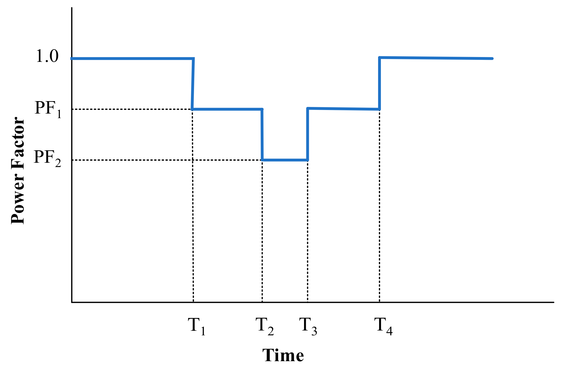
The power factor of the PV inverter is scheduled to change with the time of the day [23]. Figure 2 demonstrates a generic power factor schedule that could be adopted to regulate the grid voltage. In this mode, the power factor is decreased during midday, where the solar irradiance is expected to be the highest.

2.2.3. Power Factor Control as a Function of Injected Active Power

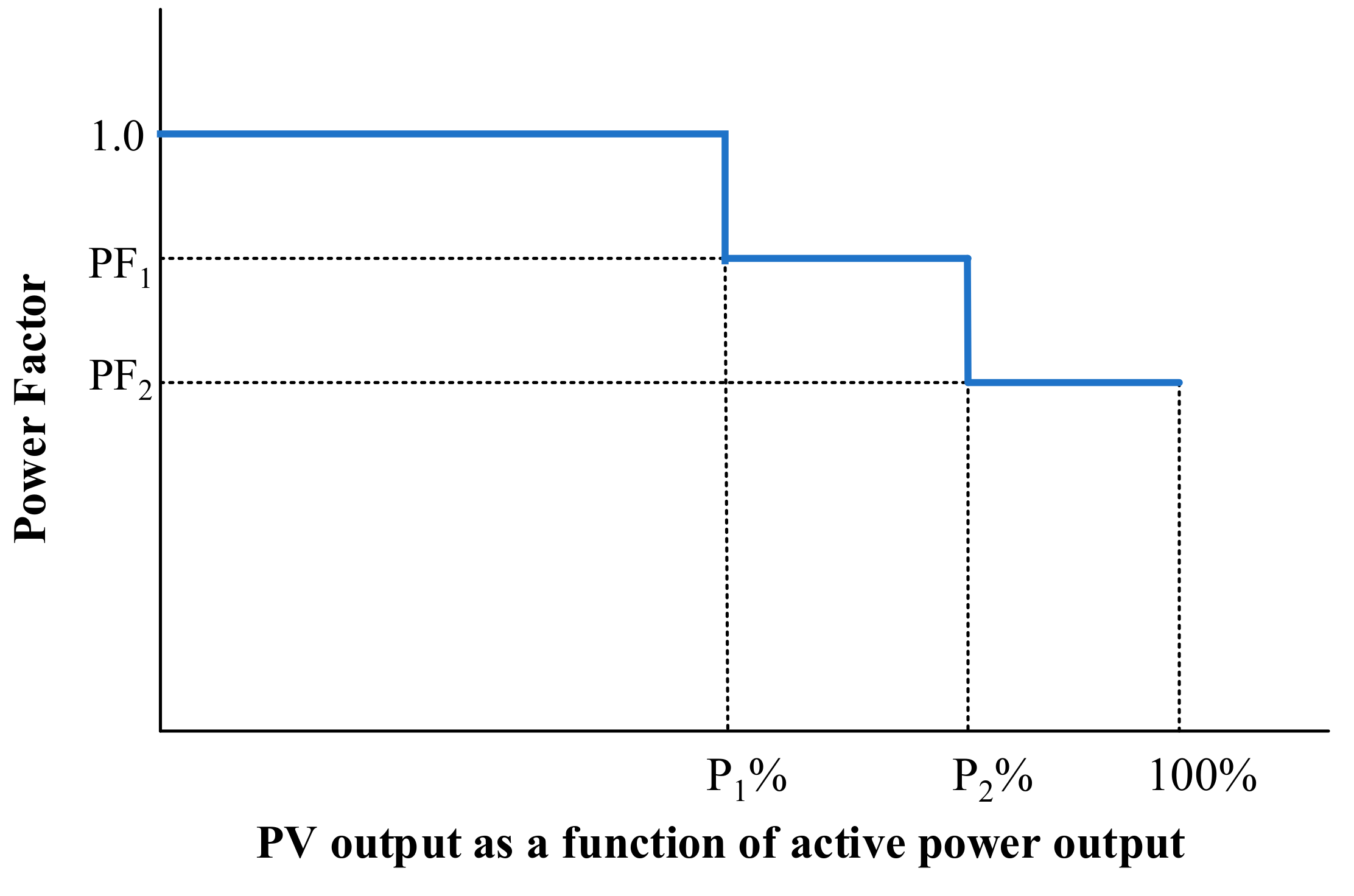
The power factor is adjusted as a function of the active power output of the PV inverter [23]. Since the active power output is proportional to the PCC voltage, the absorption of reactive power could be introduced during high solar power generation. A generic control function, such as that shown in Figure 3, could be utilized to regulate the grid voltage.

2.2.4. Voltage-Dependent Reactive Power Control (Volt-Var Control)

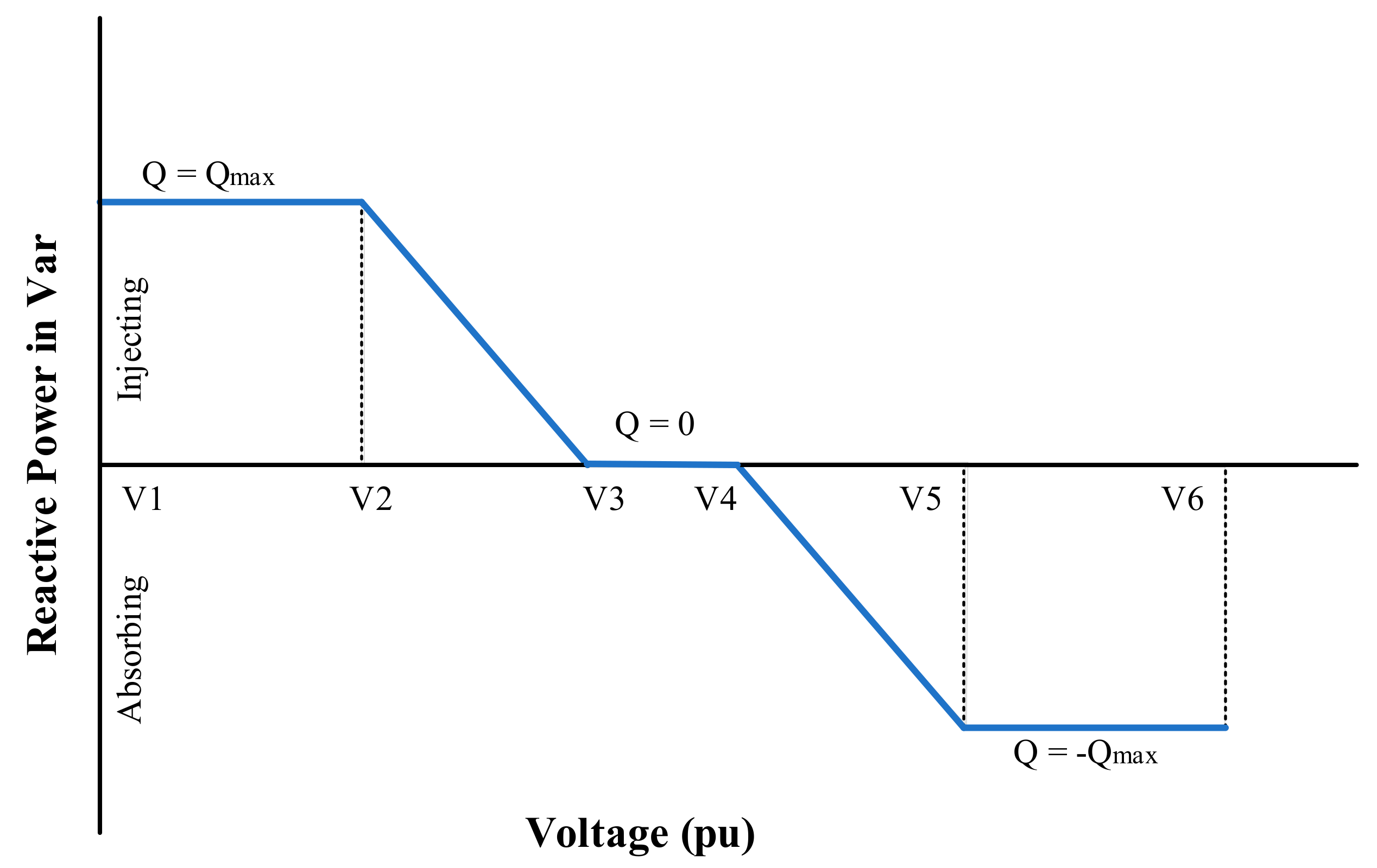
In this mode, the PV inverter is operated either to inject or to absorb reactive power as a function of the PCC voltage [17]. The amount of compensated reactive power depends on the Volt-Var setpoints defined by the user/utility. A generic Volt-Var curve is shown in Figure 4. As illustrated in the curve, if the terminal voltage drops below the pre-set lower bound (V3), the inverter injects reactive power to support the voltage at the connection point. On the contrary, if the terminal voltage exceeds the pre-set upper bound (V4), the inverter absorbs reactive power to reduce the voltage at the connection point.
The reactive power injection by the Volt-Var control can be mathematically expressed as in Equation (11).
Q t =         Q m a x t ;   if   V t V 2     V 3 V t V 3 V 2   Q m a x t ;   if   V 2 < V t V 3 0 ;   if   V 3 < V t V 4 V 4 V t V 4 V 5   Q m a x t ;   if   V 4 < V t V 5 Q m a x t ;   if   V t > V 5  
where V t is the terminal voltage and Q t is the calculated reactive power injection by the Volt-Var control.

2.3. Performance Metrics

Three performance metrics were used to quantify and compare the performance of the studied reactive power control techniques.

2.3.1. Number of Customers with Voltage Violations

This metric assesses the daily voltage profile of all customers in the network and checks compliance with local voltage limits and standards.

2.3.2. Total Daily Average Reactive Power Compensation

This metric calculates the daily average reactive power compensation ( Q a v g c o m p ) by all PV inverters connected to the grid and can be expressed as in Equation (12).
Q a v g c o m p = 1 T 0 T Q i n v t   d t  
where Q i n v is the compensated (absorbed or injected) reactive power.

2.3.3. Total Daily Average Network Loss

This metric assesses the daily average loss of the entire network ( P a v g l o s s ) and can be computed using Equation (13).
P a v g l o s s = 1 T 0 T p l o s s t   d t  
where p l o s s is the network loss, including the transformer and line losses.
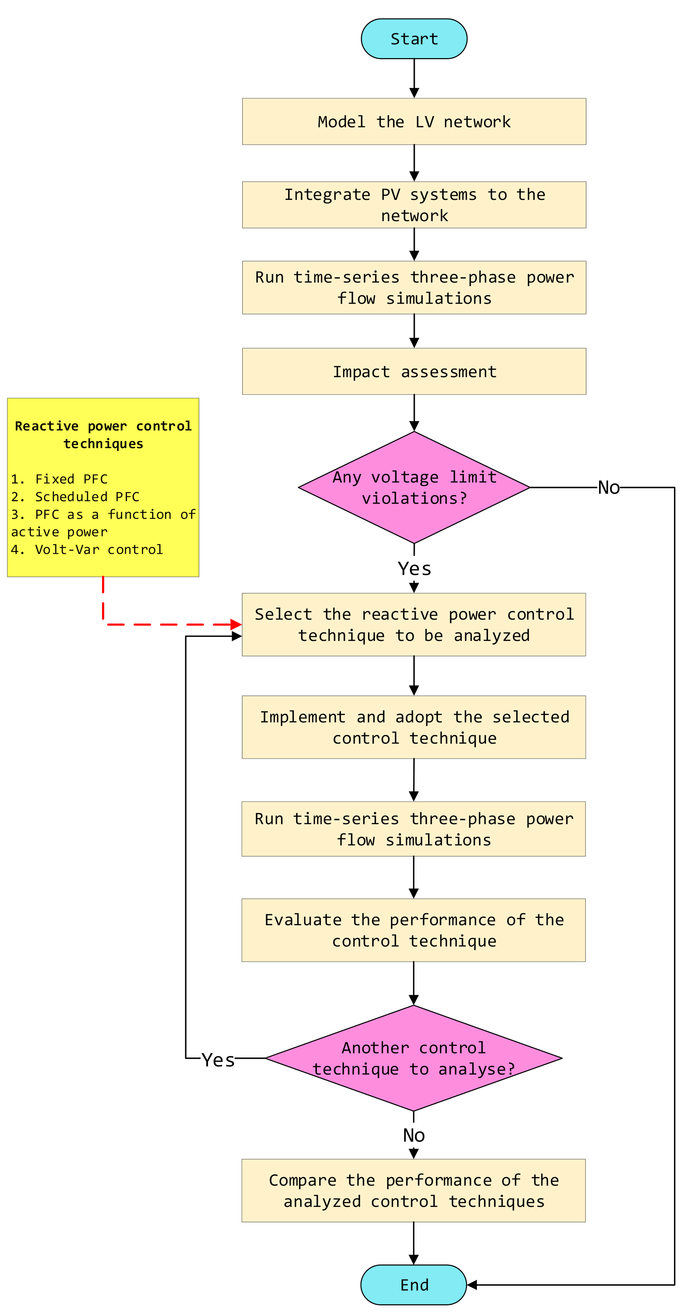
The complete flowchart of the research method is shown in Figure 5. First, a detailed network model for the selected LV distribution network was developed in the Open Distribution System Simulation (OpenDSS) software. Then, three-phase time-series power-flow simulations were performed to investigate the potential overvoltage issues with high PV penetration. Following the detection of voltage rise issues, each of the above-mentioned reactive power control techniques of the PV inverters was implemented and adopted to ensure the statutory voltage limits of the LV distribution grid. The performance of the adopted control techniques was evaluated and quantified using the three performance metrics discussed above. Finally, a comparative analysis was carried out to compare the performance of the studied reactive power controls.

2.4. Test Network

In order to evaluate the effectiveness of the studied reactive power control techniques in mitigating voltage rise due to high PV penetration, a typical Malaysian LV distribution network was modeled by using the OpenDSS software interfaced with MATLABTM. The single-line diagram of the test network is shown in Figure 6. The network comprised four feeders connected to a 1 MVA, 11/0.433 kV distribution transformer that supplied 124 customers via a three-phase connection. The peak demand of the network was presumed to be 620 kW, with a peak load of 5 kW per customer. Figure 7 demonstrates the one-minute normalized residential load profile and PV generation profiles under sunny and normal climatic conditions, which were used to conduct a high-resolution analysis.
In order to investigate the potential impact of high PV penetration in the future, all of the customers were assumed to have equally rated PV installations on their rooftops. Therefore, a 7 kWp rated PV system was connected to each household (868 kW total PV generation) to ensure overvoltage issues at peak irradiance periods. Moreover, all inverters were assumed to be 10% oversized to provide reactive power support even when delivering the maximum active power generation.

3. Results

Firstly, three-phase time-series power-flow simulations were performed for the base-case scenario (without adopting any reactive power controls) considering the daily residential load and the sunny and normal PV generation profiles. The simulation results were evaluated using local standards to investigate potential voltage violations due to high PV integration. According to the guidelines for the interconnection of distributed generators to a distribution system from the Malaysian electric utility, Tenaga Nasional Berhad,
  • The statutory tolerance limits for voltage variation should be between −6% and +10% (0.94 and 1.1 p.u.).
  • DG systems should maintain a power factor ranging from 0.85 lagging to 0.9 leading.
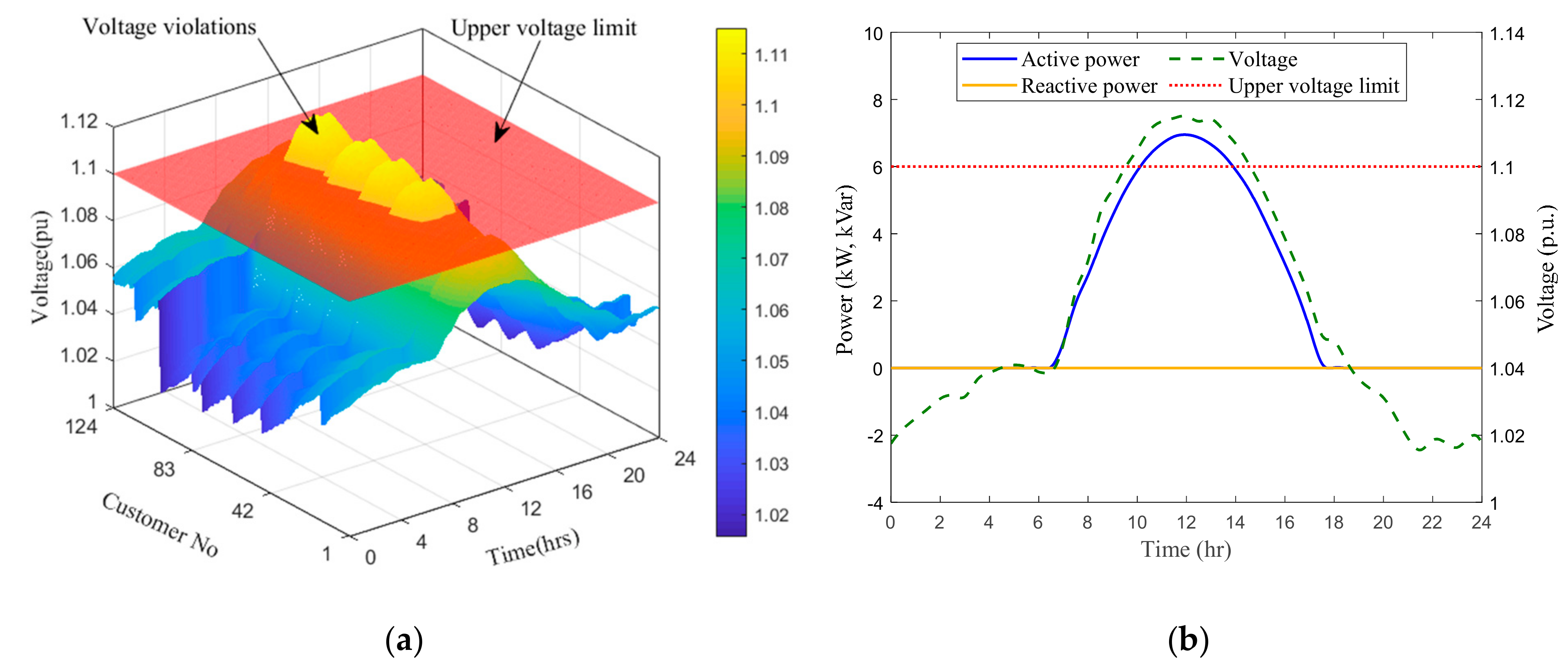
Figure 8a shows the daily voltage profiles of all 124 customers in the LV network for the sunny climatic condition with no reactive power control. As expected, a significant number of customers (66) were recorded as having upper voltage limit (1.1 p.u.) violations due to the high solar PV penetration. According to the simulation results, the maximum recorded voltage was reported at the 107th node of the network, which was also the furthest node from the distribution transformer. The daily variations of the terminal voltage and the active and reactive power output of the PV inverter connected to the critical node (i.e., the 107th node) are shown in Figure 8b.
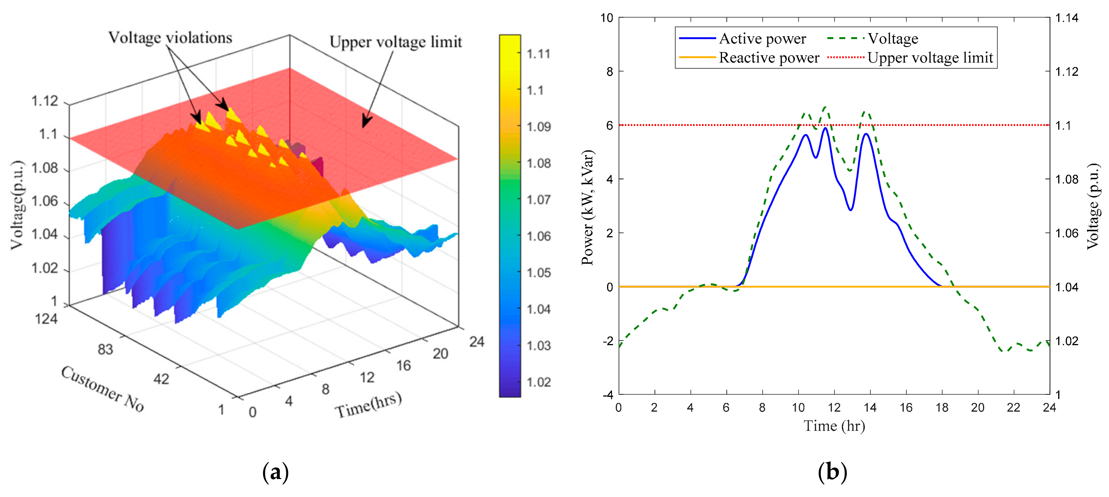
Similarly, the daily variations of the voltage of all customer nodes, as well as the terminal voltage and active and reactive power output of the PV inverter connected to the critical node, are presented in Figure 9. As per the simulation results, 34 consumers were recorded as having upper voltage limit violations.
Subsequently, each reactive power control technique was implemented and adopted to alleviate overvoltage issues for the sunny climatic condition. When implementing the controls, the most suitable settings were assigned to resolve all voltage issues.
  • For the fixed PFC, all PV inverters were operated with a leading power factor of 0.97.
  • For the scheduled PFC, 0.99 and 0.97 leading power factors were assigned for the PF1 and PF2 values, while 8.5, 9.5, 14.5, and 15.5 h were selected for the T1, T2, T3, and T4 values.
  • For the PFC as a function of injected active power technique, leading power factors of 0.99 and 0.97 were assigned for the PF1 and PF2 values, while 60% and 80% of the PV output (as a percentage of the rated capacity) were selected for the P1% and P2% values.
  • For the Volt-Var control, the setpoints were adjusted to allow the inverter to start the reactive power absorption and to absorb the maximum available reactive power when the voltage reached 1.08 and 1.1 p.u. respectively.
The daily variations of the voltages of all 124 customer nodes and the reactive power compensation of the PV inverter connected to the critical node for the fixed PFC, scheduled PFC, PFC as a function of injected active power, and Volt-Var control are shown in Figure 10.
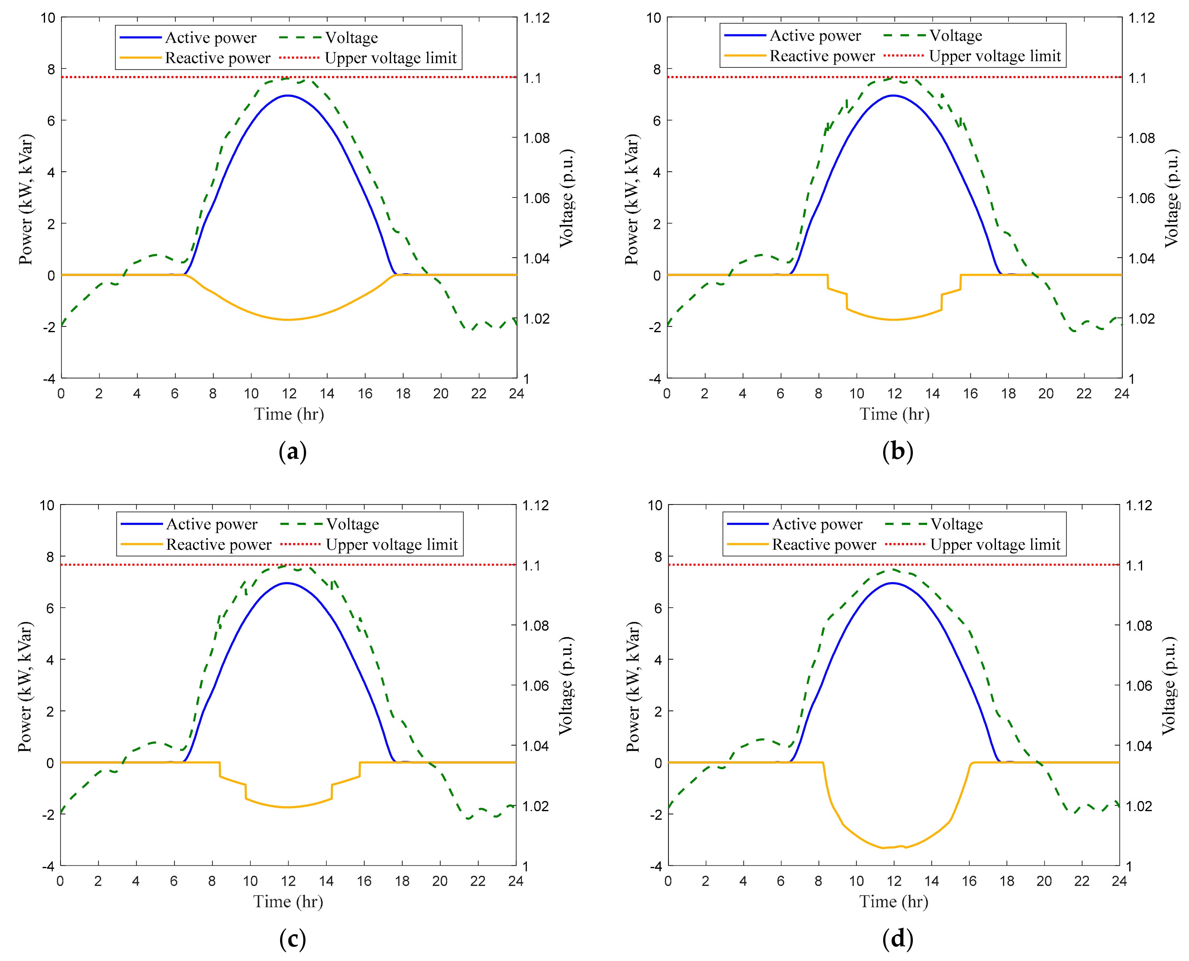
Similarly, the daily variations of the terminal voltage and active and reactive power output of the PV inverter connected to the critical node for all of the control techniques are shown in Figure 11.

4. Discussion

By examining the voltage profiles presented in Figure 10, it was revealed that the upper voltage limit violations observed in Figure 8a were completely suppressed after the adoption of all four reactive power control techniques with their corresponding settings. As depicted in Figure 10, in the PFC techniques, all customers experienced equal reactive power absorption, whereas in the Volt-Var control technique, only customers with higher voltages were significantly involved in the reactive power absorption. Furthermore, it could be clearly seen that, in the Volt-Var control, the reactive power absorption of PV inverters connected closer to the distribution transformer was negligible owing to the low terminal voltages. According to the simulation results, the maximum reactive power absorption of 3.323 kVar was observed at the critical node with the Volt-Var control. It was 43.15% of the inverter’s rated capacity of 7.7 kVA.
As illustrated in Figure 11, all control techniques were capable of preventing overvoltage problems while providing the maximum active power generation. In fact, due to the sufficient reactive power capability, the employment of overrated inverters allowed for a complete active power generation.
Table 1 summarizes and compares the performance of the studied reactive power control techniques for PV inverters.
As indicated in Table 1, the highest daily average reactive power compensation of 63.484 kVar was shown with the fixed PFC technique. In this mode, the reactive power was absorbed regardless of the active power generation. However, in the scheduled and PFC as a function of injected active power control techniques, the unnecessary reactive power provision was alleviated by adjusting the droop set points to avoid the absorption of reactive power during low PV generation. This could be clearly seen in Figure 10b,c. As a result, reductions of 24.2% and 23.6% in the daily average reactive power absorption were achieved for the scheduled and PFC as a function of injected active power control techniques relative to the fixed PFC technique, respectively.
In scheduled PFC, the selection of power factor values and scheduling times depends on the experience of the distribution engineer. Nevertheless, an unnecessary reactive power absorption could still occur in this mode when peak PV generation is not expected to occur, such as on sunny days. The main drawback of the PFC techniques is the provision of location-free reactive power references irrespective of the local voltage. In addition, these control techniques needlessly absorb reactive power at times when peak PV generation coincides with high demand where voltage violations may not occur. The minimum reactive power absorption was observed in the Volt-Var control, which corresponds to a 30.5% reduction compared to the fixed PFC.
A significant increase in network loss could be seen in all control techniques compared to the base-case scenario. The highest daily average network loss was reported with the fixed PFC technique due to the unnecessary reactive power absorption, even in occasions where voltage was not at risk of being violated. This was a 10.8% increase compared to the operation of PV inverters with a unity power factor. In the scheduled and PFC as a function of injected active power control techniques, the daily average network losses were lower than those of the other controls owing to the elimination of the excessive reactive power absorption. While the Volt-Var control was the lowest in daily reactive power compensation, it was the second-highest control in daily average network loss. This was mainly due to the fact that the reactive power passed over a long distance (high impedance) as the reactive power absorption occurred further away from the distribution transformer.
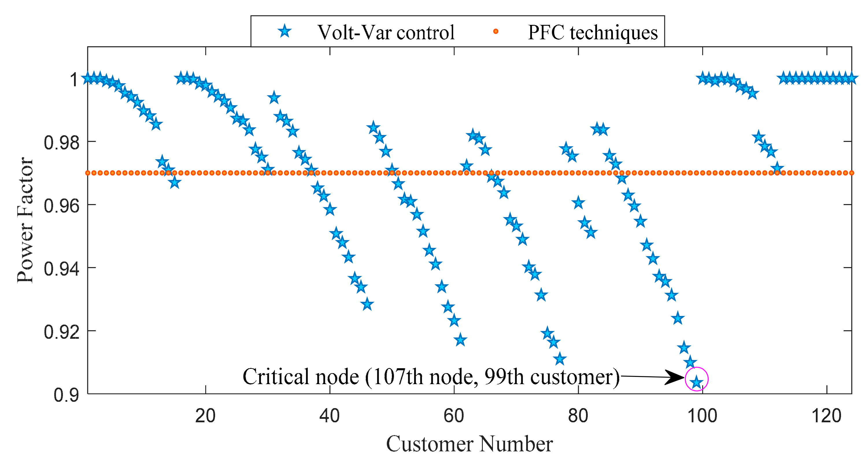
As listed in the table, in the studied PFC techniques, the power factor limit of the inverter varied at a defined value, and the minimum power factor value assigned to these controls was 0.97. However, in the Volt-Var control, a wider power factor range (1.00 to 0.90) is required compared to those required by the other controls. Figure 12 presents the variations of the power factors of PV systems connected to each customer during peak PV generation with the PFC and Volt-Var controls. As can be seen in Figure 12, in the Volt-Var control, the power factor value decreased from unity in each branch as the customer was pushed further from the starting point of the branch.
As a consequence, the power factor of the PV inverter connected to the network’s furthest node reached closer to 0.90 to maintain the terminal voltages within the admissible limits. However, all power factor values assigned or obtained by each technique fell within the Malaysian guidelines. In addition, the findings reflect the importance of using an oversized PV inverter (to enhance the reactive power capability) in Volt-Var control for customers who are located far from the distribution transformer in order to successfully suppress the overvoltage issues.

5. Conclusions

This paper explored the performance of four reactive power control techniques for PV inverters—namely, fixed PFC, scheduled PFC, PFC as a function of injected active power, and Volt-Var control—in mitigating overvoltage issues due to the high integration of PV systems. A detailed study was conducted on a typical Malaysian LV distribution network to analyze and review these control techniques in terms of the number of customers with voltage violations, reactive power compensation, and network losses. The main findings drawn from the research can be presented as follows.
  • The studied reactive power control techniques are successful in overcoming the voltage problems of typical Malaysian networks.
  • Every technique comprises inherent drawbacks that must be considered for implementation.
  • Because some of the controls compensate for excessive reactive power, which contributes to high network losses, the incorporation of efficient reactive power control techniques that provide effective voltage control while optimizing excessive reactive power compensation and network losses is required.
  • The Volt-Var control of solar PV inverters outperforms the other control techniques by providing effective voltage regulation while requiring less reactive power compensation.
  • The strengths and weaknesses of the studied reactive power control techniques could assist DNOs in making more rational decisions when implementing these controls to resolve overvoltage issues.
Future work will focus on the coordination of active power curtailment and reactive power compensation control strategies for solar PV inverters in order to achieve effective voltage regulation while increasing the PV-hosting capacity.

Author Contributions

Conceptualization, D.A., J.P. and J.E; methodology, D.A.; software, D.A.; writing—original draft preparation, D.A.; writing—review and editing, D.A., J.P. and J.E.; visualization, D.A.; supervision, J.P. and J.E.; project administration, J.P.; funding acquisition, J.P. All authors have read and agreed to the published version of the manuscript.

Funding

This research paper publication was funded through J510050002—BOLDREFRESH2025—CENTRE OF EXCELLENCE from the iRMC of Universiti Tenaga Nasional (UNITEN).

Acknowledgments

The authors would like to thank the Tenaga Nasional Berhad (TNB), Malaysia, for supporting this research under a TNB R&D Seeding Fund (U-TD-RD-19-07) and UNITEN R&D Sdn. Bhd. In addition, the authors acknowledge the publication support through J510050002—BOLDREFRESH2025—CENTRE OF EXCELLENCE from the iRMC of UNITEN.

Conflicts of Interest

The authors declare no conflict of interest.

References

  1. International Renewable Energy Agency. Future of Solar Photovoltaic: Deployment, Investment, Technology, Grid Integration and Socio-Economic Aspects; IRENA: Abu Dhabi, United Arab Emirates, 2019. [Google Scholar]
  2. Abdullah, W.S.W.; Osman, M.; Kadir, M.Z.A.A.; Verayiah, R. The potential and status of renewable energy development in Malaysia. Energies 2019, 12, 2437. [Google Scholar] [CrossRef] [Green Version]
  3. Almeida, D.W.; Abeysinghe, A.H.M.S.M.S.; Ekanayake, J.B. Analysis of rooftop solar impacts on distribution networks. Ceylon J. Sci. 2019, 48, 103. [Google Scholar] [CrossRef] [Green Version]
  4. Almeida, D.; Abeysinghe, S.; Ekanayake, M.P.; Godaliyadda, R.I.; Ekanayake, J.; Pasupuleti, J. Generalized approach to assess and characterise the impact of solar PV on LV networks. Int. J. Electr. Power Energy Syst. 2020, 121, 106058. [Google Scholar] [CrossRef]
  5. Hashemi, S.; Østergaard, J. Methods and strategies for overvoltage prevention in low voltage distribution systems with PV. Iet Renew. Power Gener. 2017, 11, 205–214. [Google Scholar] [CrossRef] [Green Version]
  6. Tonkoski, R.; Lopes, L.A.C.; El-Fouly, T.H.M. Coordinated active power curtailment of grid connected PV inverters for overvoltage prevention. IEEE Trans. Sustain. Energy 2011, 2, 139–147. [Google Scholar] [CrossRef]
  7. Ghosh, S.; Rahman, S.; Pipattanasomporn, M. Distribution Voltage Regulation through Active Power Curtailment with PV Inverters and Solar Generation Forecasts. IEEE Trans. Sustain. Energy 2017, 8, 13–22. [Google Scholar] [CrossRef]
  8. Alyami, S.; Wang, Y.; Wang, C.; Zhao, J.; Zhao, B. Adaptive real power capping method for fair overvoltage regulation of distribution networks with high penetration of PV systems. IEEE Trans. Smart Grid 2014, 5, 2729–2738. [Google Scholar] [CrossRef]
  9. Tonkoski, R.; Lopes, L.A.C.; EL-Fouly, T.H.M. Droop-based active power curtailment for overvoltage prevention in grid connected PV inverters. In Proceedings of the IEEE International Symposium on Industrial Electronics, Bari, Italy, 4–7 July 2010; pp. 2388–2393. [Google Scholar]
  10. Paudyal, S.; Bhattarai, B.P.; Tonkoski, R.; Dahal, S.; Ceylan, O. Comparative Study of Active Power Curtailment Methods of PVs for Preventing Overvoltage on Distribution Feeders. In Proceedings of the IEEE Power and Energy Society General Meeting, Portland, OR, USA, 5–10 August 2018; pp. 1–6. [Google Scholar]
  11. Gómez-González, J.F.; Cañadillas-Ramallo, D.; González-Díaz, B.; Méndez-Pérez, J.A.; Rodríguez, J.; Sánchez, J.; Guerrero-Lemus, R. Reactive power management in photovoltaic installations connected to low-voltage grids to avoid active power curtailment. Renew. Energy Power Qual. J. 2018, 1, 5–11. [Google Scholar] [CrossRef]
  12. Stetz, T.; Marten, F.; Braun, M. Improved low voltage grid-integration of photovoltaic systems in Germany. IEEE Trans. Sustain. Energy 2013, 4, 534–542. [Google Scholar] [CrossRef]
  13. Almeida, D.; Pasupuleti, J.; Ekanayake, J.; Karunarathne, E. Mitigation of overvoltage due to high penetration of solar photovoltaics using smart inverters volt / var control. Indones. J. Electr. Eng. Comput. Sci. 2020, 19, 1259–1266. [Google Scholar] [CrossRef]
  14. Ishimaru, M.; Komami, S. Positive Effect of PV’s Constant Leading Power-Factor Operation in Power System. J. Int. Counc. Electr. Eng. 2013, 3, 276–282. [Google Scholar] [CrossRef] [Green Version]
  15. Gokmen, N.; Hu, W.; Chen, Z. A simple PV inverter power factor control method based on solar irradiance variation. In Proceedings of the 2017 IEEE Manchester PowerTech, Manchester, UK, 18–22 June 2017; pp. 1–6. [Google Scholar]
  16. Chirapongsananurak, P.; Hoonchareon, N. Grid code for PV integration in distribution circuits considering overvoltage and voltage variation. In Proceedings of the IEEE Region 10 Annual International Conference, Penang, Malaysia, 5–8 November 2017; pp. 1936–1941. [Google Scholar]
  17. Smith, J.W.; Sunderman, W.; Dugan, R.; Seal, B. Smart inverter volt/var control functions for high penetration of PV on distribution systems. In Proceedings of the 2011 IEEE/PES Power Systems Conference and Exposition, PSCE 2011, Phoenix, AZ, USA, 20–23 March 2011; pp. 1–6. [Google Scholar]
  18. Jahangiri, P.; Aliprantis, D.C. Distributed Volt/VAr control by PV inverters. IEEE Trans. Power Syst. 2013, 28, 3429–3439. [Google Scholar] [CrossRef]
  19. Abdelmotteleb, I.; Gomez, T.; Chaves-Avila, J.P. Benefits of PV inverter volt-var control on distribution network operation. In Proceedings of the 2017 IEEE Manchester PowerTech, Manchester, UK, 18–22 June 2017; pp. 1–6. [Google Scholar]
  20. Juamperez, M.; Yang, G.; Kjær, S. Voltage regulation in LV grids by coordinated volt-var control strategies. J. Mod. Power Syst. Clean Energy 2014, 2, 319–328. [Google Scholar] [CrossRef] [Green Version]
  21. Ilo, A.; Schultis, D.L.; Schirmer, C. Effectiveness of distributed vs. concentrated volt/var local control strategies in low-voltage grids. Appl. Sci. 2018, 8, 1382. [Google Scholar] [CrossRef] [Green Version]
  22. Demirok, E.; Member, S.; Gonz, P.C.; Frederiksen, K.H.B.; Sera, D.; Rodriguez, P.; Member, S.; Teodorescu, R. Local Reactive Power Control Methods for Overvoltage Prevention of Distributed Solar Inverters in Low-Voltage Grids. IEEE J. Photovolt. 2011, 1, 174–182. [Google Scholar] [CrossRef]
  23. Reno, M.J.; Broderick, R.J.; Grijalva, S. Smart inverter capabilities for mitigating over-voltage on distribution systems with high penetrations of PV. In Proceedings of the IEEE Photovoltaic Specialists Conference, Tampa, FL, USA, 16–21 June 2013; pp. 3153–3158. [Google Scholar]
  24. Bell, F.; Ieee, M.; Nguyen, A.; Ieee, M.; Mccarty, M.; Ieee, M.; Bialek, T.; Ieee, M. SecondaryVoltage and Reactive Power Support via Smart Inverters on a High-Penetration Distributed Photovoltaic Circuit. In Proceedings of the 2016 IEEE Power & Energy Society Innovative Smart Grid Technologies Conference, Minneapolis, MN, USA, 6–9 September 2016; pp. 1–6. [Google Scholar]
  25. Mather, B.; Gebeyehu, A. Field demonstration of using advanced PV inverter functionality to mitigate the impacts of high-penetration PV grid integration on the distribution system. In Proceedings of the 2015 IEEE 42nd Photovoltaic Specialist Conference, New Orleans, LA, USA, 14–19 June 2015; pp. 1–6. [Google Scholar]
  26. Rahimi, K.; Tbaileh, A.; Broadwater, R.; Woyak, J.; Dilek, M. Voltage regulation performance of smart inverters: Power factor versus volt-VAR control. In Proceedings of the 2017 North American Power Symposium, Morgantown, WV, USA, 17–19 September 2017; pp. 7–12. [Google Scholar]
  27. Weckx, S.; Driesen, J. Optimal Local Reactive Power Control by PV Inverters. IEEE Trans. Sustain. Energy 2016, 7, 1624–1633. [Google Scholar] [CrossRef]
  28. Lai, L.L. Intelligent System Applications in Power Engineering: Evolutionary Programming and Neural Networks; John Wiley & Sons: New York, NY, USA, 1998. [Google Scholar]
  29. Yilmaz, M.; El-Shatshat, R. State-based Volt/VAR control strategies for active distribution networks. Int. J. Electr. Power Energy Syst. 2017, 100, 411–421. [Google Scholar] [CrossRef]
  30. Manbachi, M.; Farhangi, H.; Palizban, A.; Arzanpour, S. Smart grid adaptive volt-VAR optimization: Challenges for sustainable future grids. Sustain. Cities Soc. 2017, 28, 242–255. [Google Scholar] [CrossRef]
  31. Lai, C.S.; Locatelli, G. Economic and financial appraisal of novel large-scale energy storage technologies. Energy 2021, 214, 118954. [Google Scholar] [CrossRef]
  32. Wang, L.; Bai, F.; Yan, R.; Saha, T.K. Real-Time Coordinated Voltage Control of PV Inverters and Energy Storage for Weak Networks with High PV Penetration. IEEE Trans. Power Syst. 2018, 33, 3383–3395. [Google Scholar] [CrossRef] [Green Version]
  33. IEEE Standard Association. IEEE Std. 1547-2018. Standard for Interconnection and Interoperability of Distributed Energy Resources with Associated Electric Power Systems Interfaces; IEEE: Piscataway, NJ, USA, 2018. [Google Scholar]
  34. Electric Power Research Institute. Modeling High-Penetration PV for Distribution Interconnection Studies Smart Inverter Function Modeling in OpenDSS, Rev. 3; EPRI: Palo Alto, CA, USA, 2017. [Google Scholar]
Figure 1. Representation of a simple network structure.
Electronics 10 01569 g001
Figure 2. A generic power factor schedule for PV inverters.
Electronics 10 01569 g002
Figure 3. A generic power factor control as a function of injected active power for PV inverters.
Electronics 10 01569 g003
Figure 4. A generic Volt-Var curve.
Electronics 10 01569 g004
Figure 5. Flowchart of the research method.
Electronics 10 01569 g005
Figure 6. Single-line diagram of the test network.
Electronics 10 01569 g006
Figure 7. Normalized daily residential load and PV generation profiles.
Electronics 10 01569 g007
Figure 8. Daily variations of (a) the voltage of all customer nodes and the (b) terminal voltage and active and reactive power output of the PV inverter connected to the critical node with no reactive power control for the sunny climatic condition.
Electronics 10 01569 g008
Figure 9. Daily variations of (a) the voltage of all customer nodes and (b) the terminal voltage and active and reactive power output of the PV inverter connected to the critical node with no reactive power control for the normal climatic condition.
Electronics 10 01569 g009
Figure 10. Daily variations of the voltage of all customer nodes and the reactive power compensation of different reactive power control techniques.
Electronics 10 01569 g010aElectronics 10 01569 g010b
Figure 11. Daily variations of the terminal voltage and active and reactive power output of the PV inverter connected to the critical node with (a) the fixed PFC, (b) scheduled PFC, (c) PFC as a function of injected active power, and (d) Volt-Var control.
Electronics 10 01569 g011
Figure 12. Variation of the power factor with the customer number.
Electronics 10 01569 g012
Table 1. Simulation results of the reactive power control techniques.
ParameterBase CaseReactive Power Control Technique
Fixed PFCScheduled PFCPFC as a Function of Injected Active PowerVolt-Var Control
Number of customers with voltage violations660000
Total daily average reactive power absorption (kVar)0.00063.48448.10748.51244.103
Total daily average network loss (kW)9.80410.86610.61610.61410.829
Power factor limitMax1.000.971.001.001.00
Min0.970.970.90
Publisher’s Note: MDPI stays neutral with regard to jurisdictional claims in published maps and institutional affiliations.