Article

Improving Transient Behavior of a Brushless Doubly Fed Induction Generator through Reactive Current Control of Grid-Side Converter

1
School of Electrical Engineering, Faculty of Enigineering, Universiti Teknologi Malaysia, Skudai 81310, Johor, Malaysia
2
Department of Electrical Engineering, SZAB Campus, Mehran University of Electrical & Technology, Khairpur Mir 66020, Sindh, Pakistan
3
School of Computing, National University of Singapore, Singapore 117417, Singapore
4
Computer Science & Information Technology, Jalozai Campus, University of Engineering and Technology Peshawar, Peshawar 25000, Khyber Pakhtunkhwa, Pakistan
5
Department of Electrical Engineering, National University of Computer and Emerging Sciences, Islamabad 44000, Pakistan
*
Authors to whom correspondence should be addressed.
Electronics 2021, 10(12), 1413; https://doi.org/10.3390/electronics10121413
Submission received: 23 May 2021 / Revised: 8 June 2021 / Accepted: 10 June 2021 / Published: 11 June 2021
(This article belongs to the Section Power Electronics)

Abstract

:
Brushless doubly-fed induction generators have higher reliability, making them an attractive choice for not only offshore applications but also for remote locations. These generators are composed of two back-to-back voltage source converters, a grid side converter and a rotor side converter. Existing techniques use the rotor side converter for reactive current control; however, it is more suitable for stabilizing steady state behavior. In order to stabilize the voltage fluctuations at the point of common coupling (PCC) due to sudden inductive load introduction, the grid side converter may be a better choice due to faster response and higher control bandwidth. Therefore, this paper proposes a control scheme for the grid side converter to suppress the PCC voltage fluctuations when a large inductive load is suddenly connected. The proposed technique is based on an analytical model of the transient behavior of the voltage drop at the PCC. The analysis shows that reactive current control using the grid side converter introduces a double fundamental frequency component to the PCC voltage. To block this harmonic, we designed a notch filter. The simulation results in Matlab/Simulink show that the proposed technique can not only significantly reduce the voltage drop but also results in an 82% reduction in voltage distortion at the PCC.

1. Introduction

Renewable energy systems are penetrating mainstream power generation due to their environment friendliness and an increasing demand for energy around the world. Variable speed constant frequency wind energy generation systems have gained a lot of popularity over the last decade, thanks to the higher aerodynamic range leading to better efficiency [1], e.g., the doubly-fed induction generator. However, these systems use a brush gear, which leads to difficult deployment and maintenance in remote locations such as in offshore applications. As the name implies, the Brushless Doubly-Fed Induction Generator does not host the brush gear, and thus achieves better reliability [2,3]. Moreover, a brushless doubly-fed induction generator results in a simple structure (due to the absence of a slip gear) and, in turn, lower cost as compared to an equivalent doubly-fed induction generator. Therefore, brushless doubly-fed induction generators have lately gained the interest of many researchers and industrial applications.
A brushless doubly-fed induction generator consists of two separate sets of three-phase stator windings. The first stator winding that is directly connected to the grid is called the power winding, and is responsible for the generated power. The second stator winding called the control winding is indirectly connected to the grid through a Variable Voltage, Variable Frequency fractionally rated converter. The two stator windings have different pole pair numbers to avoid direct coupling and are coupled through the rotor [4]. The standard brushless doubly-fed induction generator control approach aims to sustain a persistent power winding voltage in the presence of loads. However, it has been demonstrated that the voltage level at the verge of common coupling, i.e., at the PCC, is prone to fluctuate when the load variation is large. Such variations affect other loads connected to the PCC and introduce torque pulsations [5]. This is especially true when a large inductive load is suddenly introduced to the PCC such as motors, transformers, and chokes. To solve this issue, this paper focuses on the problem of improving the transient behavior of a brushless doubly-fed induction generator by reducing the voltage drop when a large inductive load is suddenly connected to the PCC.
The converter used in a brushless doubly-fed induction generator comprises of a pair of consecutive voltage source converters i.e., the rotor side converter (RSC) and the grid side converter (GSC) sharing a common DC-link. Typically, an RSC indirectly regulates the power winding voltage by directly controlling the control winding current. On the other hand, the GSC is typically used to control the DC-link voltage [6]. Moreover, the GSC can also assist in injecting or consuming reactive current since the RSC is mostly used for reactive power control [7]. However, RSC reactive power control is most widely adopted for low voltage ride through situations, and it has certain disadvantages when it comes to stabilizing PCC voltage fluctuations: (i) large mechanical inertia leading to slower response [8], (ii) lower control bandwidth [9], and (iii) increased losses. On the other hand, the GSC has a faster response and higher bandwidth —thanks to being connected to the PCC at one end and the DC-link capacitor at the other end. Thus, this paper proposes a GSC control scheme to quickly reduce the PCC voltage fluctuations by injecting reactive current. The existing schemes on reactive current control through GSC are based on voltage oriented control in the synchronous reference frame. These techniques compute constant d-axis and q-axis reference values. However, such traditional control approaches are designed with steady-state performance as the focus. Thus, when an inductive load is instantaneously connected to the PCC, the conventional control scheme does not remain optimal as the transient part of the load current may be fluctuating instead of being constant. To this point, the proposed work explores the transient and steady state components of the voltage drop at the PCC. Then, based on the mathematical model, the reference value for reactive current compensation is deduced. A summary of a comparison of the existing techniques for brushless doubly-fed induction generator control and the proposed technique is shown in Table 1.
This paper focuses on developing a grid side converter control scheme to reduce the voltage drop as well as voltage fluctuations at the point of common coupling. Using an analytical model of the voltage drop at the PCC in case of sudden connection of an inductive load, the reference value for reactive current compensation is analyzed. The equivalent circuit of a brushless doubly-fed induction generator is used to analyze the steady state and transient state components of load reactive current. Subsequently, a notch filter blocks the harmonics introduced due to the reactive current compensation. It is interesting to mention that, recently, advanced control strategies [17] such as Whiplash compensation based on Pontryagin’s minimization of Hamiltonian systems have been proposed as a viable alternative to notch compensation. The major contributions of this paper are as follows:
(i)
Analyzing the effect of the reference value for reactive current on the PCC voltage drop.
(ii)
A GSC reactive current control scheme to reduce the voltage drop at PCC.
(iii)
Design of a notch filter to remove harmonics introduced as a result of reactive current compensation.
This paper is organized as follows: Section 2 presents the system model. The proposed technique is described in Section 3, and the results are discussed in Section 4. Conclusions are presented in Section 5.

2. System Model

The system model considered in this paper is shown in Figure 1. A brushless doubly-fed induction generator consists of two stator windings, i.e., stator power winding and stator control winding. The rotor winding of the brushless doubly-fed induction generator couples the two stator windings. The stator power winding is connected to a three-phase resistive-inductive load as well as to the grid (viz. a transformer). The stator control winding is composed of two back-to-back voltage source converters, i.e., the RSC and GSC. The two converters are connected through a DC-link, where the capacitor allows for an independent design of controllers for the RSC and GSC, respectively. The GSC is connected to the stator power winding at the point of common coupling. Incorporating a capacitor bank C g reduces stator power winding voltage ripples and filters out harmonics produced by the GSC. The equivalent load resistance and inductance are represented by R L and L L , respectively. The set of notations used in this paper are given in Table 2. The stator power winding and stator control winding produce p p and p c pole-pairs rotating at speeds of ω p and ω c , respectively. Consequently, the rotor winding produces induced current with angular speeds [6]:
ω r p = ω p p p ω r
ω r c = ω c p c ω r .
As ω r p = ω r c , the rotor speed is given by:
ω r = ω p + ω c p p + p c .
Thus, the operation principal of a brushless doubly-fed induction generator is to keep ω p constant by controlling ω c in response to varying ω r
Typically, the RSC regulates the stator power winding voltage using the stator control winding current. In this paper, we focus on the GSC for reactive current control because of the reasons outlined in Section 1. Therefore, the standard RSC controller based on scaler control is used in Figure 1 [18]. The standard RSC controller regulates the PCC voltage by controlling the stator control winding current. However, this method is suitable for small fans and pumps but is sub-optimal to regulate the PCC fluctuations when a large inductive-resistive load is connected. To solve this issue, the next section describes the proposed technique for GSC control.

3. Proposed Technique

This section presents the proposed technique to improve the transient behavior of a brushless doubly-fed induction generator when an inductive-resistive load is connected suddenly. As shown in Figure 1, the proposed technique consists of two controllers for the converters. Both RSC and GSC can be used for reactive current compensation; however, the GSC has a higher control bandwidth [19] and can be used to improve the transient behavior of the brushless doubly-fed induction generator, i.e., the GSC can quickly respond to variations (after connecting a load) of the PCC voltage. The per-phase steady-state equivalent circuit of a brushless doubly-fed induction generator is shown in Figure 2. The RSC and GSC are decoupled using the capacitance C d c ; therefore, these can be analyzed independently.

3.1. GSC Controller Design

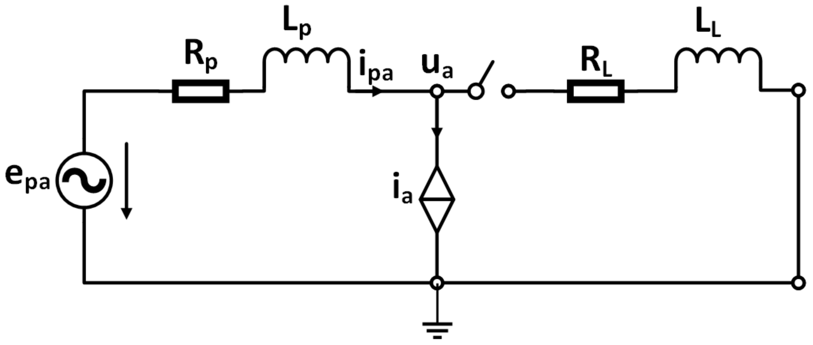
To design the GSC controller, refer to the equivalent circuit for a single-phase of the brushless doubly-fed induction generator as seen from the power winding side presented in Figure 3. i L L represents the load current of a-phase, while u a and i a represent voltage and current, respectively, for the a-phase at the PCC. Denoting the amplitude and angular frequency of the phase voltage by U m and ω , respectively, we can obtain the induced electromotive force e p a as follows [16]:
e p a ( t ) = U m cos ( ω t )
Taking the Laplace transform of (4), we obtain e p a in complex frequency domain as follows:
e p a ( s ) = U m s s 2 + ω 2
At natural speed i a = 0 , and, under normal conditions, it can be assumed without loss of generality that the grid line impedance is negligible. When a load is connected, the switch in Figure 3 will be closed and the the stator power winding current can be written as:
i p a ( s ) = e c a ( s ) L s + R = U m ( L s + R ) ( s 2 + ω 2 ) ,
where, the total inductance L, and total resistance R are given by
R = R c + R l + R s
L = L c + L L + L l
Defining the magnitude and angle of the total impedance as follows:
| Z | = R 2 + ( ω L ) 2
Φ = arctan ω L R .
Then, Equation (6) can be re-written as [16]:
i p a ( s ) = U | Z | 2 R s s 2 + ω 2 + ω 2 L s 2 + ω 2 R L L s + R
= U m | Z | s cos Φ s 2 + ω 2 + ω sin Φ s 2 + ω 2 cos Φ s + R L
Taking the inverse Laplace transform, we get:
i p a ( t ) = U m | Z | cos ( ω t Φ ) U m | Z | cos ( Φ ) e R L t .
Equation (13) shows that the power winding current is composed of two components: first, a fundamental frequency component, and, second, an exponentially decaying DC component. The equations for b and c phase currents of the stator power winding can be obtained similarly. Thus, the stator power winding current consists of a steady state component and transient component. The stator power winding current in the synchronous reference frame is obtained using Park transformation:
i p d ( t ) = U m | Z | cos Φ U m | Z | cos ( ω t + Φ ) e R L t
i p q ( t ) = U m | Z | sin Φ + U m | Z | sin ( ω t + Φ ) e R L t ,
where the steady state and transient state components can be separated as follows:
i p d s ( t ) = U m | Z | cos Φ , i p d t = U m | Z | cos ( ω t + Φ ) e R L t i p q s ( t ) = U m | Z | sin Φ , i p q t = U m | Z | sin ( ω t + Φ ) e R L t .
Thus, the active and reactive control winding currents are also composed of a DC steady state component and an exponentially decaying transient component. The synchronous reference frame voltages at the PCC are given by:
u d = e p d R p i p d L p d d t i p d ω L p i p q
u q = e p q R p i p q L p d d t i p q ω L p i p d .
Therefore, the voltage drop at the PCC can now be obtained as:
Δ u d = R p i p d + L p d d t i p d ω L p i p q
Δ u q = R p i p q + L p d d t i p q + ω L p i p d .
Substituting Equations (14) and (15) into Equations (18) and (19) and simplifying, we obtain:
Δ u d = ( R p i p d s ω L p i p q s ) + R p L L p R L i p d t
Δ u q = ( R p i p q s + ω L p i p d s ) + R p L L p R L i p q t .
Note that the drop in the voltage magnitude at the PCC is a result of the steady state component, while the distortion at the PCC is caused by the transient component. To improve the transient behavior of the brushless doubly-fed induction generator when a load is suddenly connected, the GSC needs to carry out reactive current compensation. For this purpose, the GSC can use the load current as the reference for GSC. Note that, at natural speed, i p a = i L a , i.e., the power winding and load currents are equal, which is obvious from Figure 3. Therefore, to carry out reactive current compensation, the reference for GSC is the sum of the steady state and transient components of the load reactive current as follows:
i L q = i L q s + i L q t = U m | Z | sin Φ + U | Z | sin ( ω t + Φ ) e R L t
Thus, if we denote the q-axis reference current by i q * , then i q * = i L q , and the reactive current component of the stator power winding is eliminated, i.e., i p q s = i p q t = 0 . Putting these values into Equations (20) and (21), we obtain
Δ u d = R p i p d s + R p L L p R L i p d t
Δ u q = ω L p i p d s .
Using the Park inverse transformation:
Δ u a = Δ u d cos ω t Δ u q sin ω t .
Thus,
Δ u a = U m | Z | | Z p | cos Φ cos ( ω t + ϕ ) U m | Z | R p L L p R L e R L t 1 2 cos ( 2 ω t + ϕ ) + ] 1 2 cos ϕ .
As cos Φ < 1 , therefore, the voltage drop in Equation (26) has been reduced. However, we observe a harmonic component at the double of fundamental frequency. To avoid this component, the authors in Wang et al. [16] proposed the instantaneous reactive power theory which not only increases the complexity but also results in sub-optimal performance. To eliminate the double fundamental frequency component in the voltage at PCC after reactive current compensation by the GSC, we propose the use of a notch filter. Notch filters have been used effectively for harmonic rejection [20,21]. The proposed GSC controller is shown in Figure 4. Note that calculation of the reference current i q * from load current is the essential difference with the standard GSC controller shown in Figure 5.

3.2. Notch Filter Design

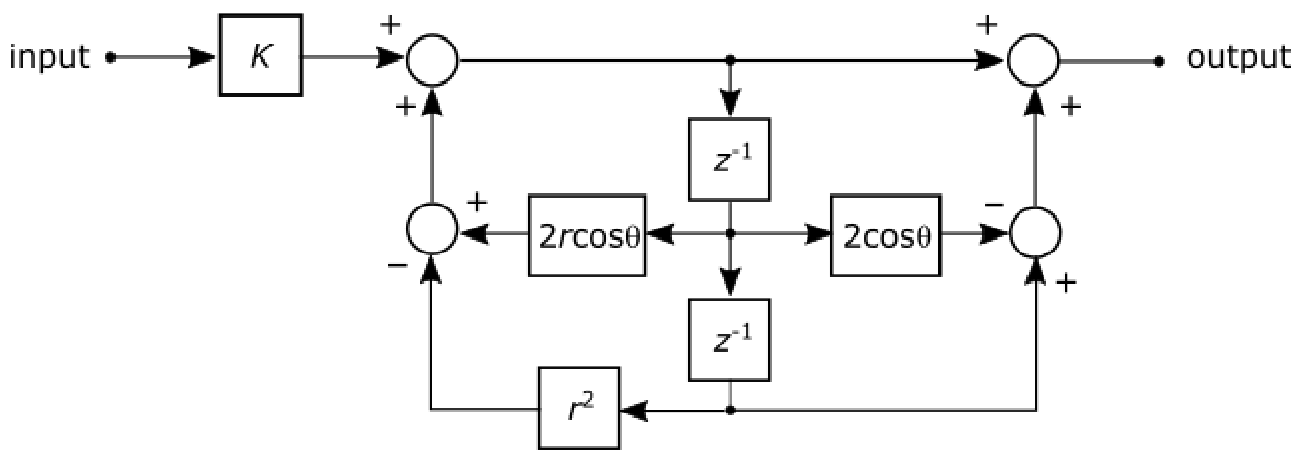
A notch filter is a system that allows frequencies in a narrow band and rejects frequencies outside of that band. Commonly known as band-stop or band-reject filters, notch filters can be employed as a pre-filter to reject harmonics not removed by feedback controllers [22,23]. Such a rejection is needed to improve the speed of response and/or bandwidth of the system. The design of notch filters is straightforward for simple linear and time-invariant systems. However, designing for systems of larger complexity such as the one considered in this work is challenging because of the uncertainties and nonlinearities arising from switched components. Once the lightly damped mode, the complex pair of poles causing the harmonic is estimated for a linearized system. Then, a complex pair of zeros with slighter greater damping and slightly lower natural frequency must be placed in the s-plane. This is to ensure that the root-locus stays away from the right-half plane [21]. Following the design guidelines in [24], we use a second-order band-stop digital notch filter that has a transfer function as follows:
H z = K z 2 2 z cos θ + 1 z 2 2 r z cos θ + r 2 .
where
θ = f 0 f s , r 1 BW f s π , K = 1 2 r cos θ + r 2 2 2 cos θ .
Here, f 0 is the center frequency, and BW is the 3-dB bandwidth. The notch filter parameters are given in Table 3.
The block diagram implementation of a notch filter with the parameters in Table 3 and Equation (28) is shown in Figure 6.
One such notch filter is included as a pre-filter for each phase as indicated by blocks labeled NF in Figure 4. The frequency response of the notch filter is shown in Figure 7.
The successful rejection of the unwanted frequency can be attributed to the high quality factor Q = f 0 / BW = 50 .

4. Results and Discussion

In this section, we present results to evaluate the effectiveness of the proposed controller. We compare the performance of the proposed technique with the technique proposed in [16] using simulations in Matlab/Simulink. The simulation parameters are given in Table 4.
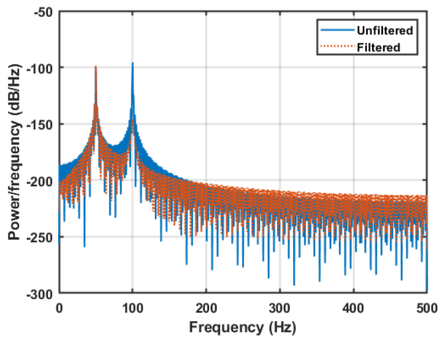
The frequency response of the voltage drop with and without the notch filter is plotted in Figure 8. We observe a double fundamental frequency harmonic without any filtering. However, using the proposed notch filter, the double frequency harmonic has been compensated significantly. It can be observed that the notch filter reduces the double fundamental frequency harmonic significantly to near rejection.
To assess the performance of the proposed technique, we consider three scenarios:
(i)
Base: This is the case where the brushless doubly-fed induction generator is simulated without any protection, i.e., without the proposed technique.
(ii)
Proposed: This the case where the proposed technique is used for GSC control.
(iii)
Wang et al.: The GSC is controlled using one of the most recent and relevant techniques proposed in Wang et al. [16].
To first observe the voltage drop as a result of suddenly connecting an inductive load with 30 KVARs of reactive power rating at 3 ms, we present Figure 9. We observe that, without any compensation for sudden load connection, the voltage drop is quite significant. However, using the proposed technique or Wang et al., the voltage drop is significantly reduced. Moreover, the voltage drop using the proposed technique is at least 0.5 p.u. and 0.1 p.u. less than the based case and Wang et al., respectively.
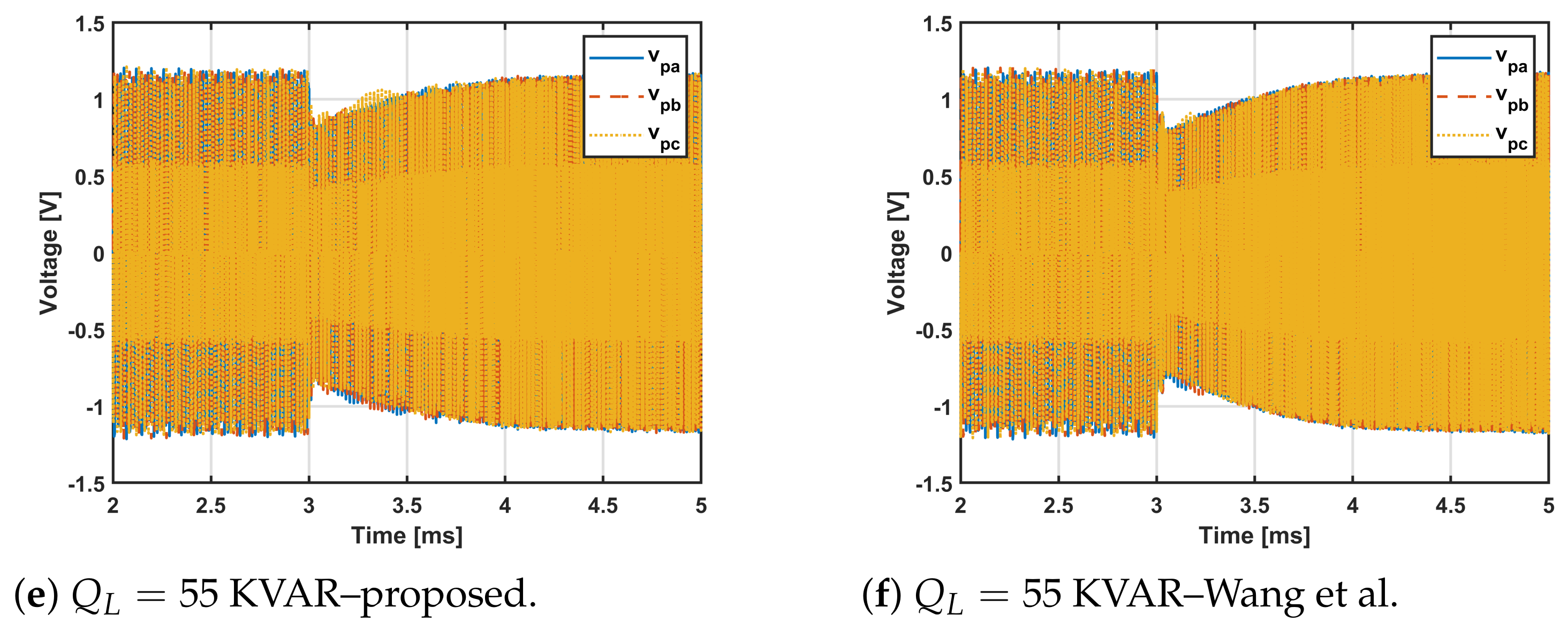
To gain further insights, we consider three inductive loads with increasing reactive power in kVARs, namely, 30, 45, and 55. The active power of the load is fixed at 5 KW. The inductive load is connected at time 3 ms and the objective is to minimize the voltage drop while eliminating the double frequency harmonic using the notch filter. The corresponding power winding voltage is presented in Figure 10. We observe that the voltage drop in the case of the proposed technique is reduced because the double frequency harmonic, rejected by the notch filter, is prevented from slowing down the voltage recovery. The improvements achieved by the proposed technique are delineated obviously in Table 5.
It can be seen that, in all the three cases, the proposed technique offers an improvement of nearly 0.1 p.u. over Wang et al. [16] in the power winding voltage drop. This improvement can be attributed to the nearly 82 % reduction in total harmonic distortion (THD) by the notch filter.
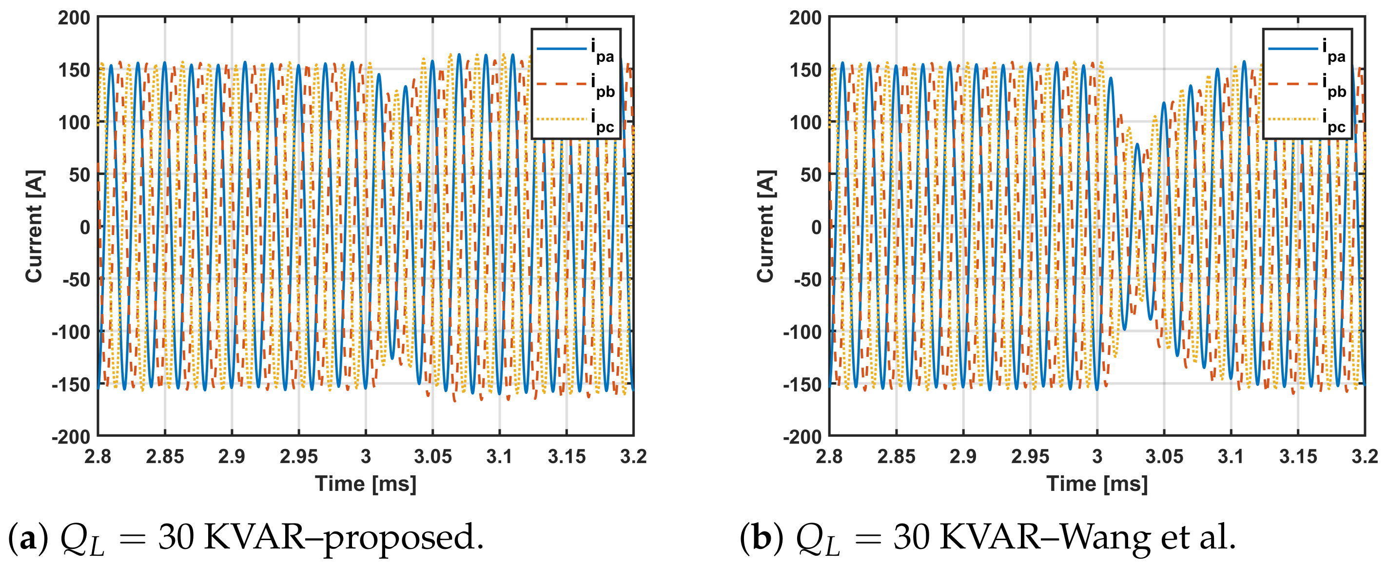
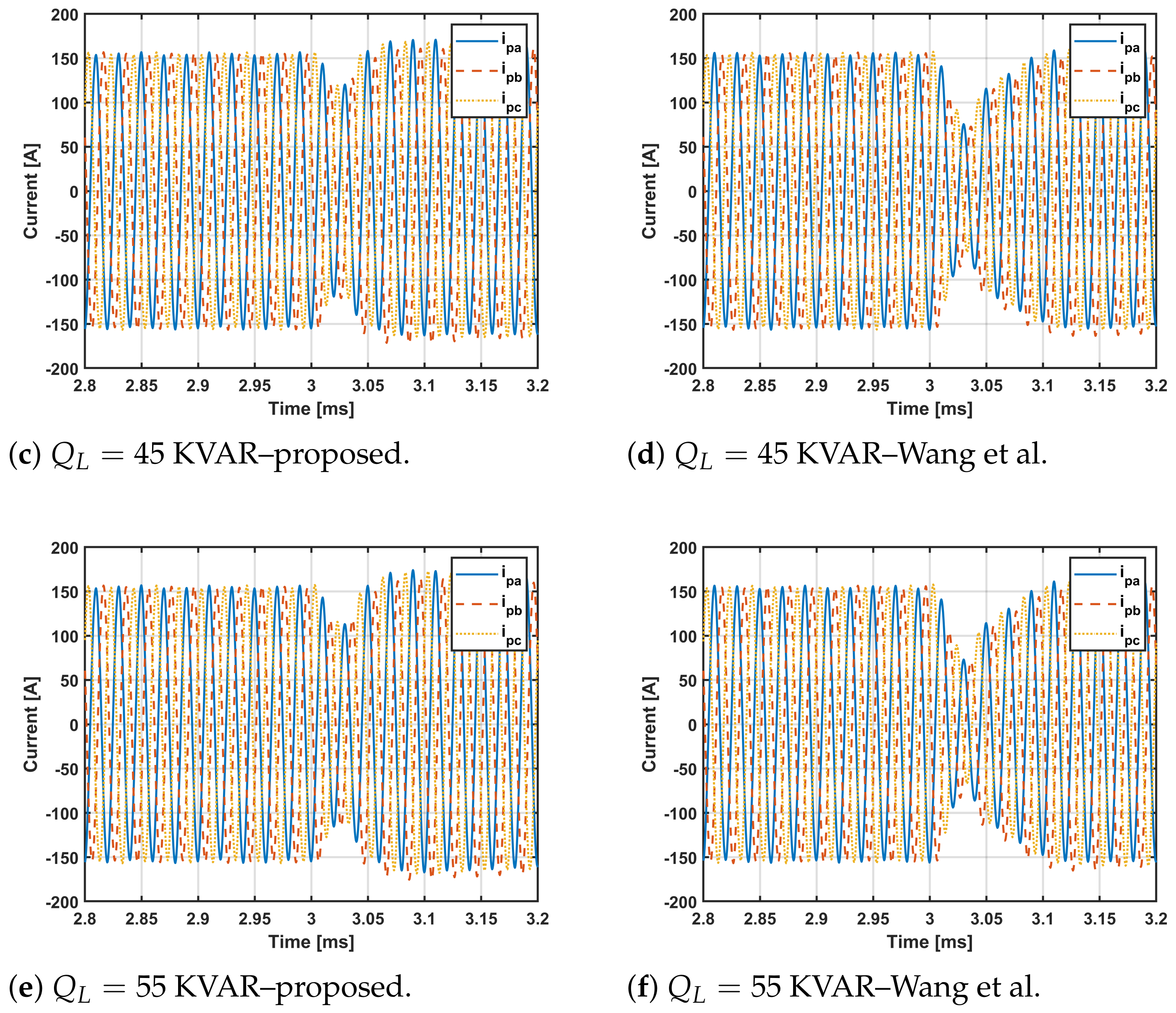
Figure 11 shows the power winding current for three inductive loads. It can be observed that the proposed technique clearly outperforms the technique in Wang et al. [16] by maintaining the power winding current above 0.7 p.u. in all cases, while the current reduces to 0.3 p.u. in Wang et al. [16]. As explained earlier, the fast recovery of power winding current can be attributed to the prevention (by notch filter) of the double frequency harmonics to slow down the recovery. This is apparent from a zoomed in view of Figure 11 presented in Figure 12.

5. Conclusions

This paper presented a reactive current control technique for the grid side converter of a brushless doubly-fed induction generator. The objective of the proposed control technique is to improve the transient behavior when an inductive load is suddenly connected to the point of common coupling. The brushless doubly-fed induction generator is represented by an equivalent circuit. Then, the single phase equivalent circuit seen from the grid side converter is used to analyze the steady state and transient state components of the voltage drop. The voltage drop is minimized using the q-axis load current as the reference for reactive current control. However, a double fundamental frequency harmonic is observed after using the q-axis load current as a reference. To block this harmonic, a notch filter is designed that removes the double fundamental frequency component. The proposed controller was thoroughly evaluated using simulations in Matlab/Simulink. The results show that the proposed technique can reduce the voltage drop by 0.5 p.u and 0.1 p.u. as compared to the standard control scheme and existing reactive current control techniques for the grid side converter of a brushless doubly-fed induction generator, respectively. The proposed technique also reduces the distortion at the point of common coupling by 82% as compared to existing techniques.

Author Contributions

Conceptualization, A.M., M.W.M. and M.U.; Methodology, A.M., M.N.A. and A.H.; Supervision, M.W.M. and M.N.A.; Validation, A.M., A.H. and M.U.; Visualization, A.M. and M.U.; Writing—original draft, A.M. and M.N.A.; Writing—review and editing, M.W.M., M.N.A. and A.H. All authors have read and agreed to the published version of the manuscript.

Funding

This research received no external funding.

Acknowledgments

The authors would like to acknowledge the facilities provided by Universiti Teknologi Malaysia for the accomplishment of this work. Furthermore, the authors greatly acknowledge the support by the Higher Education Commission of Pakistan.

Conflicts of Interest

The authors declare no conflict of interest.

References

  1. Mohammed, O.O.; Mustafa, M.W.; Aman, M.N.; Salisu, S.; Otuoze, A.O. Capacity benefit margin assessment in the presence of renewable energy. Int. Trans. Electr. Energy Syst. 2020, 30, etep12502. [Google Scholar] [CrossRef]
  2. Larik, R.M.; Mustafa, M.W.; Aman, M.N.; Jumani, T.A.; Sajid, S.; Panjwani, M.K. An Improved Algorithm for Optimal Load Shedding in Power Systems. Energies 2018, 11, 1808. [Google Scholar] [CrossRef] [Green Version]
  3. Larik, R.M.; Mustafa, M.W.; Aman, M.N. A critical review of the state-of-art schemes for under voltage load shedding. Int. Trans. Electr. Energy Syst. 2019, 29, e2828. [Google Scholar] [CrossRef] [Green Version]
  4. Moazen, M.; Kazemzadeh, R.; Azizian, M.R. Model-based predictive direct power control of brushless doubly fed reluctance generator for wind power applications. Alex. Eng. J. 2016, 55, 2497–2507. [Google Scholar] [CrossRef] [Green Version]
  5. Das, J.C. Effects of Harmonics. In Power System Harmonics and Passive Filter Designs; John Wiley & Sons: Hoboken, NJ, USA, 2015; pp. 331–378. [Google Scholar]
  6. Sadeghi, R.; Madani, S.M.; Ataei, M. A New Smooth Synchronization of Brushless Doubly-Fed Induction Generator by Applying a Proposed Machine Model. IEEE Trans. Sustain. Energy 2018, 9, 371–380. [Google Scholar] [CrossRef]
  7. John Justo, J.; Ro, K.S. Control strategies of doubly fed induction generator-based wind turbine system with new rotor current protection topology. J. Renew. Sustain. Energy 2012, 4, 043123. [Google Scholar] [CrossRef]
  8. He, W.; Yuan, X.; Hu, J. Inertia Provision and Estimation of PLL-Based DFIG Wind Turbines. IEEE Trans. Power Syst. 2017, 32, 510–521. [Google Scholar] [CrossRef]
  9. Wu, Y.K.; Yang, W.H. Different Control Strategies on the Rotor Side Converter in DFIG-based Wind Turbines. In Proceedings of the 3rd International Conference on Power and Energy Systems Engineering, CPESE 2016, Kitakyushu, Japan, 8–10 September 2016; pp. 551–555. [Google Scholar]
  10. Gholizadeh, M.; Tohidi, S.; Oraee, A.; Oraee, H. Appropriate crowbar protection for improvement of brushless DFIG LVRT during asymmetrical voltage dips. Int. J. Electr. Power Energy Syst. 2018, 95, 1–10. [Google Scholar] [CrossRef]
  11. Tohidi, S.; Abdi, E.; Shao, S.; Zolghadri, M.; McMahon, R.; Tavner, P.; Oraee, H. Low voltage ride-through of DFIG and brushless DFIG: Similarities and differences. Electr. Power Syst. Res. 2014, 110, 64–72. [Google Scholar] [CrossRef]
  12. Tohidi, S.; Oraee, H.; Zolghadri, M.R.; Shao, S.; Tavner, P. Analysis and enhancement of low-voltage ride-through capability of brushless doubly fed induction generator. IEEE Trans. Ind. Electron. 2013, 60, 1146–1155. [Google Scholar] [CrossRef] [Green Version]
  13. Tohidi, S.; Oraee, H.; Zolghadri, M.R.; Rahimi, M. A control scheme to enhance low voltage ride-through of brushless doubly-fed induction generators. Wind Energy 2016, 19, 1699–1712. [Google Scholar] [CrossRef]
  14. Long, T.; Shao, S.; Abdi, E.; McMahon, R.A.; Liu, S. Asymmetrical low-voltage ride through of brushless doubly fed induction generators for the wind power generation. IEEE Trans. Energy Convers. 2013, 28, 502–511. [Google Scholar] [CrossRef]
  15. Long, T.; Shao, S.; Malliband, P.; Abdi, E.; McMahon, R.A. Crowbarless fault ride-through of the brushless doubly fed induction generator in a wind turbine under symmetrical voltage dips. IEEE Trans. Ind. Electron. 2013, 60, 2833–2841. [Google Scholar] [CrossRef]
  16. Wang, X.; Lin, H.; Wang, Z. Transient Control of the Reactive Current for the Line-Side Converter of the Brushless Doubly-Fed Induction Generator in Stand-Alone Operation. IEEE Trans. Power Electron. 2017, 32, 8193–8203. [Google Scholar] [CrossRef]
  17. Sands, T. Optimization Provenance of Whiplash Compensation for Flexible Space Robotics. Aerospace 2019, 6, 93. [Google Scholar] [CrossRef] [Green Version]
  18. Perelmuter, V. Simulation with Sumulink and SimPowerSystems. In Renewable Energy Systems; CRC Press: Boca Raton, FL, USA, 2017. [Google Scholar]
  19. Protsenko, K.; Xu, D. Modeling and Control of Brushless Doubly-Fed Induction Generators in Wind Energy Applications. IEEE Trans. Power Electron. 2008, 23, 1191–1197. [Google Scholar] [CrossRef]
  20. Chittora, P.; Singh, A.; Singh, M. Harmonic current extraction and compensation in three phase three wire system using notch filter. In Proceedings of the 2015 IEEE Recent Advances in Intelligent Computational Systems (RAICS), Trivandrum, India, 10–12 December 2015; pp. 422–427. [Google Scholar]
  21. Silva, J.F.; Pinto, S.F. 35-Linear and Nonlinear Control of Switching Power Converters. In Power Electronics Handbook, 4th ed.; Rashid, M.H., Ed.; Butterworth-Heinemann: Oxford, UK, 2018; pp. 1141–1220. [Google Scholar]
  22. Franklin, G.F.; Powell, J.D.; Emami-Naeini, A.F. Feedback Control of Dynamic Systems, 7th ed.; Pearson: New York, NY, USA, 2015. [Google Scholar]
  23. Lurie, B.J.; Enright, P.J. Classical Feedback Control with Nonlinear Multi-Loop Systems, 3rd ed.; Routledge & CRC Press: Boca Raton, FL, USA, 2019. [Google Scholar]
  24. Tan, L.; Jiang, J. Chapter 8—Infinite Impulse Response Filter Design. In Digital Signal Processing, 2nd ed.; Tan, L., Jiang, J., Eds.; Academic Press: Boston, MA, USA, 2013; pp. 301–403. [Google Scholar]
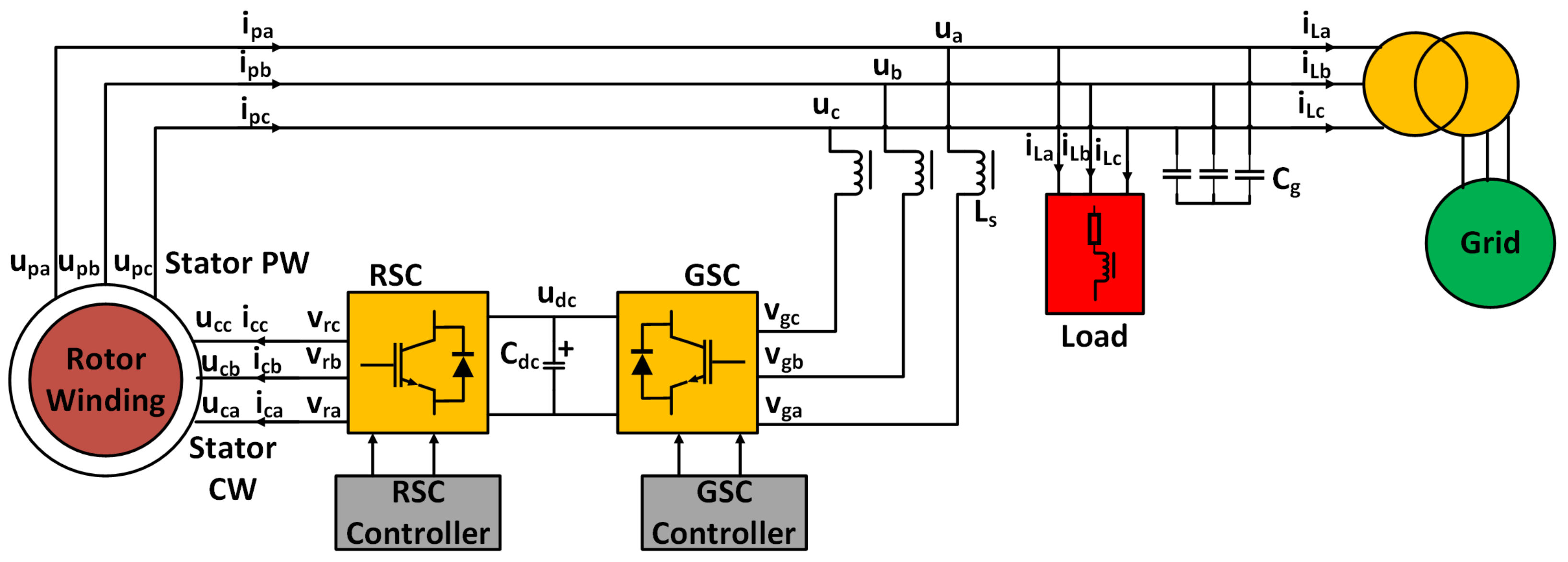
Figure 1. System model.
Electronics 10 01413 g001
Figure 2. Brushless doubly-fed induction generator equivalent circuit.
Electronics 10 01413 g002
Figure 3. Single-phase equivalent circuit from power winding.
Electronics 10 01413 g003
Figure 4. Proposed GSC controller.
Electronics 10 01413 g004
Figure 5. The standard GSC controller, modified from [18].
Electronics 10 01413 g005
Figure 6. Notch Filter: block diagram.
Electronics 10 01413 g006
Figure 7. Notch filter: frequency response.
Electronics 10 01413 g007
Figure 8. Power spectrum of voltage drop.
Electronics 10 01413 g008
Figure 9. Comparison of voltage magnitude at PCC.
Electronics 10 01413 g009
Figure 10. Comparison of the proposed technique with Wang et al. [16]—power winding voltage.
Electronics 10 01413 g010aElectronics 10 01413 g010b
Figure 11. Comparison of the proposed technique with Wang et al. [16]—power winding current.
Electronics 10 01413 g011aElectronics 10 01413 g011b
Figure 12. Power winding current—zoomed in.
Electronics 10 01413 g012
Table 1. Summary of existing brushless doubly-fed induction generator Control Techniques.
Feature[10][11][12][13][14][15][16]Proposed
Grid Side Converter Control
DC-link Control
Crowbarless Design
Point of common coupling Voltage Stabilization
Harmonic Mitigation
Grid Side Converter Control: Does the technique use GSC Control?
DC-link Control: Can the technique perform DC-link voltage control?
Crowbarless Design: The technique does not require a crowbar?
Point of common coupling Voltage Stabilization: Does the technique provide voltage stabilization at the PCC?
Harmonic Mitigation: Can the technique address oscillations introduced due to reactive current control?
Table 2. Table of notations.
NotationDescription
PCCPoint of common coupling
RSCRotor side converter
GSCGrid side converter
ω p , ω c , ω r speeds of stator power winding, stator control winding, and Rotor, respectively.
ω n Natural frequency
u p a , u p b , u p c Three phase stator power winding voltage
u c a , u c b , u c c Three phase stator control winding voltage
u a , u b , u c Three phase stator power winding voltage at PCC
u d c DC-link voltage
v r a , v r b , v r c Three phase rotor side converter voltage
v g a , v g b , v g c Three phase grid side converter voltage
i p a , i p b , i p c Three phase stator power winding current
i c a , i c b , i c c Three phase stator control winding current
i L a , i L b , i L c Three phase load current
i T a , i T b , i T c Three phase grid current
C d c DC-link capacitor
C g capacitor bank
L s , L L Filter, load inductance
R s , R L Internal, load resistance
R p , R c , R r Stator power winding, stator control winding, and rotor resistance
L p , L c , L r Stator power winding, stator control winding, and rotor leakage inductance
L r p , L r c Magnetizing inductance of rotor to stator power winding, and rotor to stator control winding
p.u.per unit
Table 3. Parameter of the 2nd-order notch filter
ParameterSymbolUnitsValue
Center frequency f 0 Hz100
Sampling rate f s Hz1000
3-dB bandwidthBWHz2
Table 4. Simulation parameters.
ParameterValue
Matlab/Simulink VersionR2020b
Simulation typeDiscrete
SolverVariable step ode23tb(stiff/TR-BDF2)
Sample time 10 5 s
Rated Power40 kVA
Power factor0.8
Rated Stator power winding Voltage120 V
Rated stator power winding current150 A
Rated operating frequency50 Hz
Switching frequency4 kHz
p p , p c 2, 6
ω n 475 rpm
C d c , u d c 0.01 F, 700 V
L s , L p , L c , L r 0.214 p.u., 0.0715. p.u., 0.0122 p.u., 0.0133 p.u.
R p , R c , R r 0.017 p.u., 0.0108 p.u., 0.047 p.u.
L r p , L r c 19.223 p.u., 5.035 p.u.
Table 5. Voltage drop comparison.
Q L Voltage Drop (p.u.)THD (%)
Wang et al. [16]Proposed
Technique
ImprovementWang et al. [16]Proposed
Technique
Improvement
300.850.950.1 p.u.22.24.081.9%
450.820.90.08 p.u.23.94.282.4%
550.780.880.1 p.u.27.24.981.9%
Publisher’s Note: MDPI stays neutral with regard to jurisdictional claims in published maps and institutional affiliations.