Article

A Low-Complexity Pilot-Based Frequency-Domain Channel Estimation for ICI Mitigation in OFDM Systems

by
Francisco J. Martín-Vega
* and
Gerardo Gómez
Departamento de Ingeniería de Comunicaciones, Campus de Excelencia Internacional Andalucía Tech., Universidad de Málaga, 29071 Málaga, Spain
*
Author to whom correspondence should be addressed.
Electronics 2021, 10(12), 1404; https://doi.org/10.3390/electronics10121404
Submission received: 8 May 2021 / Revised: 3 June 2021 / Accepted: 8 June 2021 / Published: 10 June 2021
(This article belongs to the Special Issue Channel Estimation and Modulation)

Abstract

:
A low-complexity pilot pattern and a frequency-domain channel estimation method for Inter-Carrier Interference (ICI) mitigation is proposed for Orthogonal Frequency Division Multiple Access (OFDM) systems. The proposed method exploits the band structure of the coupling matrix to perform an ICI-free channel estimation in the frequency domain. This ICI-free estimation relies on some conditions imposed over the pilot pattern that simplify the complexity of channel estimation significantly, since its complexity is the same as classical least squares (LS) channel estimation used in low mobility scenarios. Then, the ICI is removed by using a modified version of Minimum Mean Square Error (MMSE) equalization, which reduces the computational complexity considerably. This modified MMSE equalization relies on the sparse and banded structure of the coupling matrix and on a low complexity variant of the Cholesky decomposition, which is named L D L H factorization. It is shown that the proposed method greatly improves the Bit Error Rate (BER) in the high Signal-to-Noise Ratio (SNR) regime.

1. Introduction

Orthogonal frequency division multiplexing (OFDM) has been widely applied to different areas such as digital video broadcasting, power-line communications, underwater communications, wireless local area networks and cellular communications, among others. This success is motivated by the fact that, with OFDM, the entire channel is divided into narrowband flat sub-channels, which are transmitted in parallel to maintain a high date rate. The use of OFDM provides the following two advantages: (1) OFDM is robust against frequency selective fading, allowing to perform a simple one-tap equalization; (2) OFDM provides further flexibility to use advanced techniques (on a sub-carrier basis) such as adaptive loading or transmit diversity, which improves the transmission efficiency [1]. Nevertheless, in high mobility environments, such as the vehicular [2,3] and railway [4] scenarios considered in 4G and 5G cellular networks, the coherence time of the channel can be smaller than the symbol duration. When this occurs, the orthogonality among sub-carriers is lost, leading to inter-carrier interference (ICI), which severely degrades the performance of OFDM. This issue has motivated an extensive area of research that has proposed different approaches to combat the ICI caused by the time-varying channel. These approaches can be categorized as: linear equalization, that involves estimating and inverting the channel matrix to cancel out the ICI; iterative interference cancellation, where estimated symbols from one iteration are used to mitigate the interference term and improve the symbol detection in the next iteration; and ICI self-mitigation, which requires a pre-processing of the OFDM symbols to reduce the ICI power or squeeze it among a reduced number of sub-carriers.
Linear equalization for ICI mitigation has received a lot of attention in early works, since it is the natural extension of the classical equalization used in the absence of ICI. In [5], it is shown that under the assumption that the channel impulse response (CIR) varies in a linear fashion during a symbol period, the output/input relationship between transmitted and received OFDM symbols can be expressed as a diagonal-dominant sparse matrix (i.e., banded matrix). This matrix is known in the literature as subcarrier coupling matrixand it has dimensions N × N , being N the fast Fourier transform (FFT) size. This band structure of the coupling matrix is used to reduce the complexity of the matrix inversion required to perform equalization, since the inversion of a N × N matrix is reduced to N 2 Q inversions of 2 Q × 2 Q matrices, being Q the number of non-zero diagonals. This complexity reduction is further improved on [6], using Jacobi stationary iterative algorithm, and [7], which uses low complexity L D L H factorization for minimum mean square error (MMSE) equalization.
The linear model for the time variation of the CIR is also exploited in [8]. In this work, the channel matrix is split into two components: mid-point and slope of the CIR that are estimated separately. Then, two methods are proposed to estimate the slope, which are based on the redundancy of the cyclic prefix (CP) and on the information of two OFDM symbols, respectively. However, the proposed method is still complex since it requires to perform several matrix inversions, FFT operations and channel interpolations to estimate the transmitted sequence.
A novel pilot pattern and channel estimation method for ICI mitigation is proposed in [9]. The proposed pilot pattern is a combination of comb-type and grouped patterns that allows ICI mitigation with a small pilot density. Nevertheless, that scheme is numerically complex since it requires to obtain the most significant paths of the CIR, FFT operations and an iterative process to obtain the data.
Iterative interference cancellation [10,11,12,13,14,15] has been also widely investigated, since it has the potential to exploit the temporal diversity of the time varying channel to improve the performance. Nevertheless, the cost to pay is a higher computational complexity than linear equalizers like least squares (LS) and MMSE.
Finally, ICI self-mitigation is a promising approach that has attracted research interest in the last years. In [16,17,18], a time domain window is applied on the received OFDM symbols to concentrate the ICI power on the main diagonal of the coupling matrix. Recently, in [19] an adaptive windowing technique is proposed. This scheme is able to track directly an optimal receiver window in terms of average signal-to-interference and noise (SINR) ratio, requiring only linear complexity.
Other schemes reduce the ICI power instead of concentrating it. A correlative precoding scheme is proposed on [20] to offer a balance between ICI self-mitigation, spectral confinement and peak-to-average power ratio (PAPR) reduction. In [21] a mapping of each data symbol onto several sub-carriers with proper weighting coefficients is proposed to reduce the ICI power although the spectral efficiency is also reduced. In [22,23], an appealing scheme involving a linear combination of the ISI-free part of the OFDM symbols is proposed to suppress the ICI power. This scheme, which was treated heuristically in above works, is analyzed mathematically on [24], to derive the optimum weights for the combination of the ISI-free part. Although the complexity of this scheme is reduced compared to other approaches, its performance is severely degraded if the delay spread is close to the CP length, since the ISI-free part is reduced. Although the ISI-free part might be increased by extending the CP length, it should be noted that this method leads to an undesired reduction in the spectral efficiency.
As can be noticed from the literature review, ICI mitigation is a challenging task, where finding an appropriate balance between receiver complexity, spectral efficiency, and bit error rate (BER) is complicated. On the one hand, iterative interference cancellation approaches offer a high performance in terms of BER at the expense of a prohibitively receiver complexity for many applications. ICI self-mitigation schemes greatly reduce the receiver complexity. However, they either require a pre-processing that is incompatible with existing communication standards, such as 4G Long Term Evolution Advance (LTE-A) or 5G New Radio (NR) [20,21], or they reduce the spectral efficiency [22,23,24]. On the other hand, linear equalization has been proven to achieve a good performance with low complexity MMSE equalization [7], and it can be implemented with existing communication standards. However, channel estimation is in this case challenging since ICI and channel variations between pilot symbols in the time domain may lead to outdated and noisy estimated channel samples [25]. In addition, sophisticated channel estimation schemes can increase the receiver complexity, and the pilot pattern must be carefully devised to avoid reducing the spectral efficiency.
All these issues motivated us to investigate channel estimation and linear equalization for ICI mitigation with reduced complexity. In this paper we propose a low-complexity pilot pattern and a novel frequency domain coupling matrix estimation for ICI mitigation in OFDM systems. The proposed method uses a pilot pattern with some reserved sub-carriers to avoid ICI in the estimation of the channel matrix. Then, a low complexity L D L H factorization is used to mitigate the ICI through MMSE equalization. It is shown that the proposed method achieves a great improvement in terms of Bit Error Rate (BER) in the high Signal-to-Noise Ratio (SNR) regime, compared to existing approaches of similar complexity, which are based on classical 1-tap zero forcing.
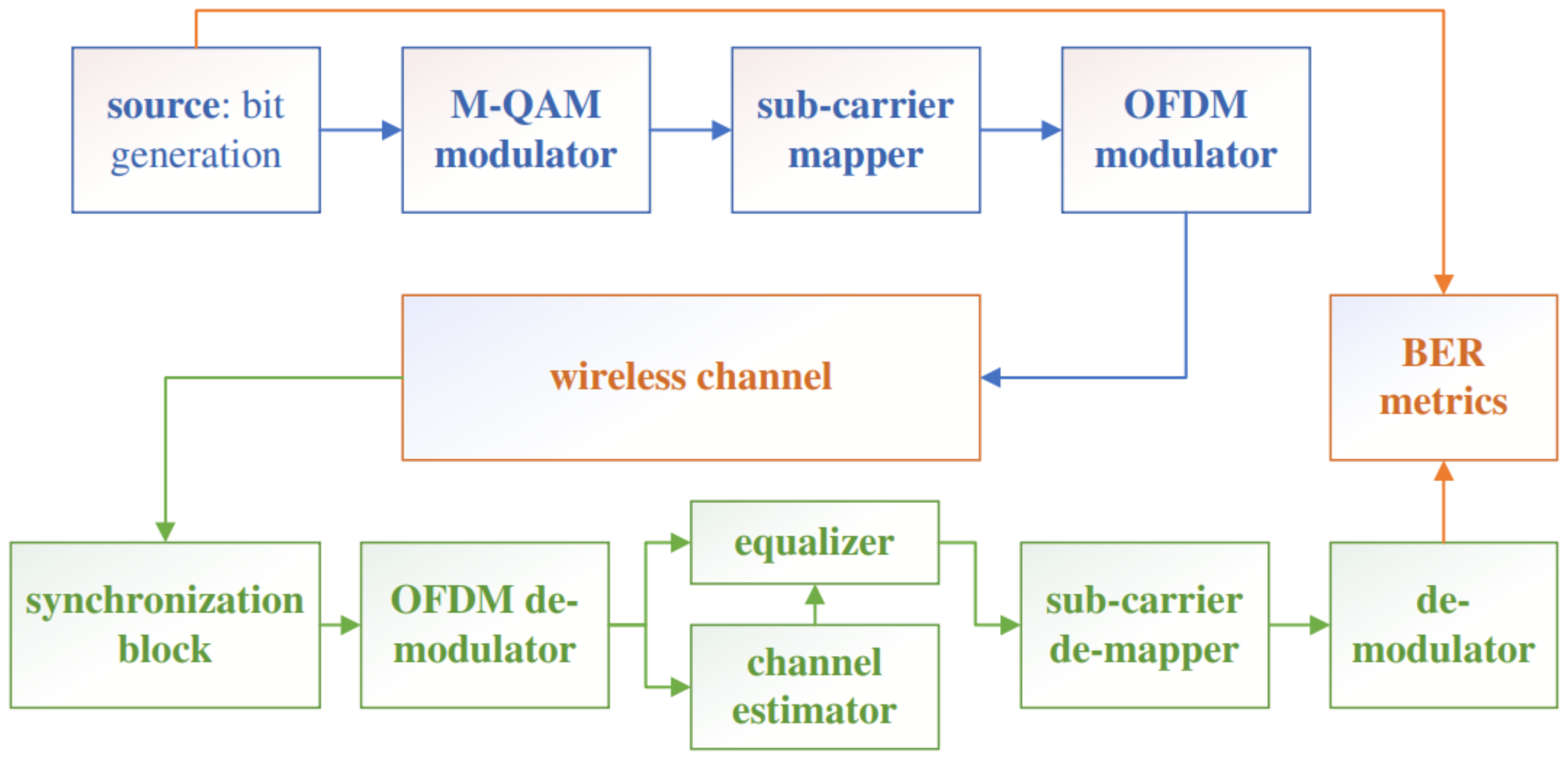
The rest of the paper is structured as follows. The system model that considers the definition of sub-carrier coupling matrix, the OFDM modulation and classical channel estimation, interpolation and equalization, is presented in Section 2. The proposed pilot pattern and low complexity channel estimation is described in Section 3. Next, the low complexity channel equalization that relies on the band structure of the channel coupling matrix is presented in Section 4. Finally, numerical results showing the benefits of the proposal and the conclusions drawn from this work are detailed in Section 5 and Section 6, respectively.
Notation: Matrices and vectors are represented in bold. The ( i , j ) -th element (i.e., i-th row and j-th column) of a given matrix, B , is represented as B ( i , j ) = B i , j . The same holds for vectors, e.g, X C N × 1 and X ( k ) = X k . Transpose and conjugate transpose operations are represented as ( · ) T and ( · ) H respectively. Being P a set, | P | represents its number of elements. Z stands for the integer numbers, whereas N stands for the natural numbers including { 0 } , i.e., { 0 , 1 , 2 , } . { a : b } represents the interval of integer numbers ranging from a to b with an unitary step, which is also expressed as [ a , b ] Z . mod ( a , b ) stands for the modulo operation between a and b, which is the remainder of the Euclidean division of a by b; and · stands for the floor function. A B is the intersection of sets A and B . I N is the identity matrix of dimension N, and 0 N × 1 is the zero vector whose length is N. Finally, if H represents a given random variable (RV), H ^ represents an estimation of it.

2. System Model

2.1. OFDM Modulation and Sub-Carrier Coupling Matrix

We consider an OFDM system with perfect time and frequency synchronization. We also assume that the power amplifiers are ideal, i.e., they always work in the linear region, and thus, there is no distortion nor out-of-band emission due to the high PAPR exhibited by OFDM [26]. We have considered N sub-carriers with G samples reserved for the CP; hence, the m-th time domain OFDM symbol can be expressed as follows:
x n ( m ) = 1 N k = 0 N 1 X k ( m ) e j 2 π N k n , G n N
where X k ( m ) represents the transmitted complex symbol on sub-carrier k and j = 1 . It is assumed that the CP is longer than the maximum delay spread of the channel, L, in order to avoid ISI. Hence, the samples of the received OFDM symbol are
y n ( m ) = l = 0 L 1 h n , l ( m ) x n l ( m ) + w n ( m ) , G n N
being h n , l ( m ) the time-varying CIR sample at the time instant n of the m-th OFDM symbol in the sample lag l, whereas w n ( m ) is a sample of additive white Gaussian noise. We can write the above output/input relation in matrix form. Let us define the vector of transmit and receive time-domain samples as x ( m ) = [ x 0 ( m ) , . . , x N 1 ( m ) ] T and y ( m ) = [ y 0 ( m ) , . . , y N 1 ( m ) ] T . Then, the received vector can written as
y ( m ) = h ( m ) · x ( m ) + w ( m ) = h ( m ) F H X ( m ) + F H W ( m )
where h ( m ) denotes the (time-variant) circular convolution matrix whose ( n , l ) -th element is expressed as
h ( m ) ( n , l ) = h n , n l N ( m )
where N stands for the modulo operation. The matrix F C N × N stands for the discrete Fourier transform (DFT) matrix, whose ( k , n ) -th element can be expressed as F ( k , n ) = 1 N e j 2 π N k n . Hence, the OFDM received symbol in the frequency domain is expressed as
Y ( m ) = F y ( m ) = F h ( m ) F H X ( m ) + W ( m ) = H df m ( d , k ) X ( m ) + W ( m )
where H df m ( d , k ) = F h ( m ) F H stands for the sub-carrier coupling matrix, which models the output/input relation between transmit and receive symbols in the frequency domain. The ( d , k ) -th element of the coupling matrix can be computed as
H df m ( d , k ) = 1 N n = 0 N 1 l = 0 N 1 h ( m ) ( n , l ) e j 2 π N ( d n l k )
It can be proven that this element can be also expressed as [16] H df ( m ) ( d , k ) = h df ( m ) ( d k , k ) being h df ( m ) ( d , k ) = 1 N n = 0 N 1 l = 0 N 1 h n , l ( m ) e j 2 π N ( d n + l k ) . The proof follows from the fact that h n , l ( m ) = 0 for l L and the relation between time-varying CIR and circular convolution matrix given by (4).
For low mobility conditions, the channel can be considered as time-invariant in a given OFDM symbol, i.e., h n , l ( m ) = h l ( m ) . Therefore, the coupling matrix is a diagonal matrix whose elements are expressed as
H k ( m ) = 1 N l = 0 N 1 h l ( m ) e j 2 π N l k ,
and hence, there is no ICI. In this latter case, the output/input relationship of the channel at a given sub-carrier k and symbol m can be expressed as:
Y k ( m ) = H k ( m ) · X k ( m ) + W k ( m ) .
As a consequence, channel estimation based on pilots can be done in the frequency domain with a small computational complexity. Assuming that a given OFDM symbol has a pilot ( X k ( m ) = α k ) on sub-carriers that belong to the set k P , then the channel estimate, H ^ k ( m ) , can be obtained with a LS criteria [27] as
H ^ k ( m ) = Y k ( m ) α k = H k ( m ) + W k ( m ) α k .
As can be observed, the second term, W k ( m ) / α k , represents the estimation error. Since this error has zero mean, an averaging of the channel estimates over a time and frequency window (where the channel can be considered constant) is typically performed. Nevertheless, if the time and frequency coherence of the channel is smaller than the pilot density in frequency and time domains, the channel cannot be considered as constant, and thus, such an averaging cannot be done. Under such circumstances, the channel estimation is less accurate.
Once channel estimates are available on OFDM symbol and sub-carrier with pilots, channel interpolation is needed in time and frequency domains for equalization purposes. In this work, we have considered the following interpolation methods: (i) Zero Order Hold (ZOH); (ii) linear; and (iii) spline. The former method leads to a less computational complexity at the expense of achieving a worst performance whereas the latter method achieves the best performance at a higher computational cost.
Finally, once channel estimates are available at each ( m , k ) pair with data for a group of OFDM symbols, 1-tap Zero Forcing (ZF) equalization is done as follows
X ^ k ( m ) = Y k ( m ) / H ^ k ( m ) .

2.2. Link Simulator

Figure 1 illustrates the functional blocks related to the link simulator that is used to assess the performance of the proposed ICI mitigation mechanism.
On the transmitter side, the source block generates bits grouped in transport blocks (TBs) that are transmitted in different sub-frames. The overhead of reference signals (pilots) is taken into account to generate each TB, since the number of data bits depends on the number of pilots symbols and pilots tones per sub-frame. The bits are mapped into IQ symbols that belong to a M-QAM modulation in the modulator block. This block groups the bits in vectors of log 2 ( M ) bits that are mapped into a complex constellation symbol, s C , with unit power E [ | s | 2 ] = 1 . Gray mapping is considered to map the bits into complex symbols.
Then, the sub-carrier mapper block inserts reference signals for channel estimation on different OFDM symbols and sub-carriers depending on the chosen pilot pattern. The resource grid of LTE-A and 5G NR has been considered, and thus, each sub-frame corresponds to 1 ms that spans over 14 OFDM symbols. On the frequency domain, resources are divided in physical resource blocks (PRBs) that consist of 12 sub-carriers, each of them named as resource elements (REs) in the context of LTE-A and 5G NR.
Different pilot patterns can be analyzed in this paper, including: (i) Cell Specific Reference Signal (CRS) pattern of LTE-A ([28] figure 6.10.1.2-1); (ii) comb-type pattern [29], where a set of sub-carriers has reference signals on each OFDM symbol; and (iii) our proposed pilot pattern defined in Section 3. For comb-type pattern, the parameter F spac defines the pilot density on the frequency domain, since 1 sub-carrier out of F spac sub-carriers will be reserved for reference signals with this scheme. Nevertheless, since every symbol has pilots, the degradation due to outdated channel estimation is minimal.
Once the resource grid related to a given sub-frame is completed, IQ constellation symbols are used by the OFDM modulator block, which generates the 14 OFDM symbols of each sub-frame, adding the CP to each of them. As seen with (1) for each of the 14 OFDM symbols, the OFDM modulator receives a block of N complex symbols. Figure 2 illustrates a block diagram of the OFDM modulator. There are N A active sub-carriers and N ν = N N A guard band sub-carriers. Hence, the complex symbols, X k ( m ) , k [ 0 , N 1 ] , can be either allocated to active sub-carriers (containing pilots tones and/or data) or they can be guard bands with zero power (null symbols) to avoid out of band emissions. The symbol X ̲ k , k [ 0 , N A ] refers to the complex symbols related to active sub-carrier. To perform the OFDM modulation, the block of complex symbols X k ( m ) , k [ 0 , N 1 ] is delivered to an inverse FFT (IFFT) block. Then, in order to add the CP, the G time-samples that fall within the interval n [ N G , N 1 ] are copied at the beginning of the OFDM symbol, i.e., on time instants n [ G , 1 ] .
The generated time domain waveform undergoes time and frequency selective fast fading by the wireless channel block, which can simulate an arbitrary power-delay profile.
On the receiver side, the signal feeds the synchronization block, which implements time and frequency synchronization by using the redundancy added with the CP [30]. This frequency synchronization allows to mitigate carrier frequency offsets related to a line-of-sight (LOS) component of the channel, if present.
The synchronized signal passes through the OFDM de-modulator block, which subtracts the CP and performs FFT to get IQ complex symbols on frequency domain. These IQ symbols are used by the channel estimator block, which selects the sub-carriers with reference signals to perform channel estimation. Once the channel estimates are obtained and interpolated, the equalizer block performs equalization of IQ data symbols that are collected by the sub-carrier de-mapper block. The channel estimation and equalization can follow the classical 1 tap ZF approach described in Section 2.1 or it can follow our proposed approach detailed in Section 3 and Section 4.
Finally, equalized symbols are detected by the DeMod block, which obtains a detected TB. This detected TB is compared with the transmitted TB to compute the BER.

3. Proposed Pilot Pattern and Frequency-Domain Coupling Matrix Estimation

In this section, the proposed pilot pattern is presented, which relies on the band structure of the coupling matrix to obtain interference free samples of it. To this end, our proposed pattern uses OFDM pilot symbols without data, thus allowing to perform a simple LS estimation, although at the expense of reducing the spectral efficiency.
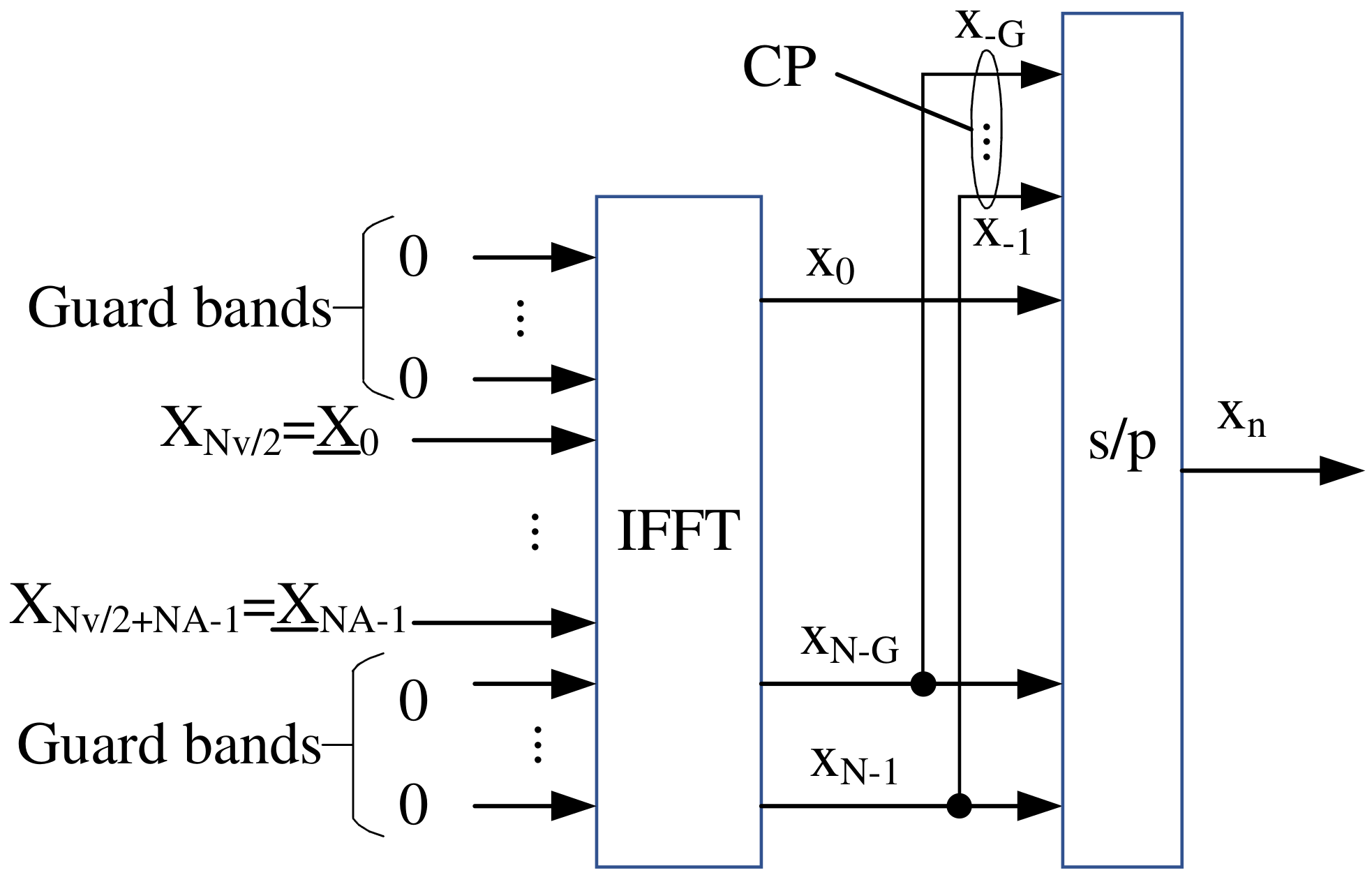
We assume that N A sub-carriers are active, and thus, N ν = N N A sub-carriers are used as guard band. Hence, we can write X = [ 0 1 × N ν / 2 , X ̲ T , 0 1 × N ν / 2 ] T , being X ̲ = X ( N ν / 2 : N ν / 2 + N A 1 ) the transmitted vector in active sub-carriers. As can be observed, the sub-carrier indexes are shifted between the elements of these vectors, and hence, the k-th element of X ̲ = [ X ̲ 0 , , X ̲ N A 1 ] T is expressed as X ̲ k = X k + N ν / 2 . From now on, the OFDM symbol index (m) is neglected for notation simplicity. Equivalently, the received vector in active sub-carriers can be written as Y ̲ = H ̲ df X ̲ + W ̲ , where H ̲ df is the N A × N A matrix obtained by selecting the central block of H df , i.e., H ̲ df = H df N ν 2 : N ν 2 + N A 1 , N ν 2 : N ν 2 + N A 1 . Y ̲ C N A × 1 and W ̲ C N A × 1 are the central blocks of vectors Y C N × 1 and W C N × 1 , respectively. It has been shown in [16] and [5] that the sub-carrier coupling matrix of the channel has a band structure, and the interference that undergoes the k-th sub-carrier mainly comes from the 2 Q neighboring sub-carriers. This means that most of the energy of the coupling matrix relies in the 2 Q + 1 central diagonals; hence, it can be accurately approximated by a band matrix.
As proven in [5], this banded structure is the result of the assumption that the CIR varies in a linear fashion within an OFDM symbol. It is shown in [5] that this linear approximation is valid for normalized Doppler frequencies, f d = v f c c Δ f up to 0.1 , being v the relative velocity in m/s, c the light speed, f c the carrier frequency in Hz, and Δ f 
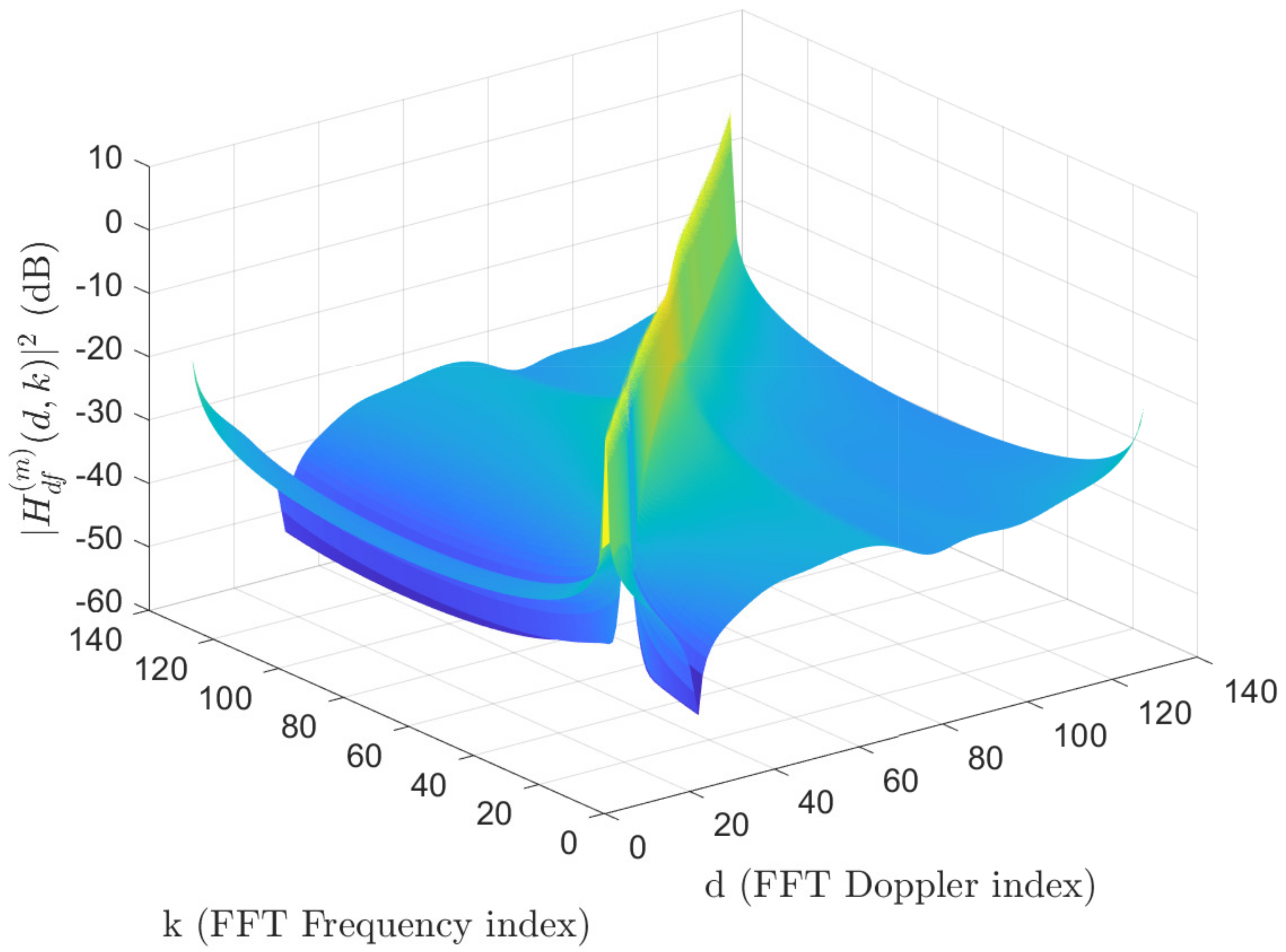
the OFDM sub-carrier spacing in Hz. In order to illustrate the banded structure of H df ( d , k ) , Figure 3 shows the coupling matrix assuming a receiver speed of 500 km/h at a carrier frequency of 2 GHz. It can be shown that most of the energy is concentrated in a few bands close to the main diagonal.
Hence, the coupling matrix can be well approximated as its banded version, either if we include or exclude the guard bands, i.e., H df B and H ̲ df B ̲ , where
B ̲ ( d , k ) = H ̲ df ( d , k ) , if | d k | Q 0 , if | d k | > Q
If the coupling matrix follows the band structure of (11), then, the received symbol in the frequency domain can be expressed as
Y ̲ d = k I d B ̲ ( d , k ) X ̲ k + W ̲ d I d = [ max ( 0 , d Q ) , min ( N A 1 , d + Q ) ]
The set I d can be obtained as the intersection of the set of sub-carrier locations with non-zero elements in the banded matrix, { k N : | d k | Q } , and the range of active sub-carriers, [ 0 , N A 1 ] .
Our proposed pilot pattern considers that OFDM symbols with pilots are spaced in T spac symbols, i.e., pilot symbols are transmitted periodically with period T spac . Since pilot symbols do not carry data, the efficiency of this scheme, η prop , computed as the ratio between sub-carriers used for data and useful carriers within a period, is given by:
η prop = ( T spac 1 ) / T spac
For those OFDM symbols with pilots, the spacing between consecutive pilots is F spac sub-carriers in the frequency domain and the rest of sub-carriers in such symbols are reserved. Hence, being X ̲ = [ X ̲ 0 , , X ̲ N A 1 ] T an OFDM symbol with pilots, X ̲ k = α k if k P and X ̲ k = 0 if k P , where α k C is the pilot value and P represents the set of pilot locations, which can be written as
P = k N : k = k 0 + p · F spac , p 0 , N A 1 k 0 F spac , k 0 [ 0 , N A 1 ] .
The symbol k 0 represents the smaller sub-carrier index with a pilot in the frequency domain, i.e., the first sub-carrier with pilots, whereas p stands for the pilot tone index, ranging from 0 up to N A 1 k 0 F spac , since the sub-carrier must fall within the interval [ 0 , N A 1 ] . It should be noticed that the set of sub-carriers with pilots can be also expressed in the equivalent form: P = { k N : k k 0 F spac = 0 , k 0 [ 0 , N A 1 ] } , where a b 
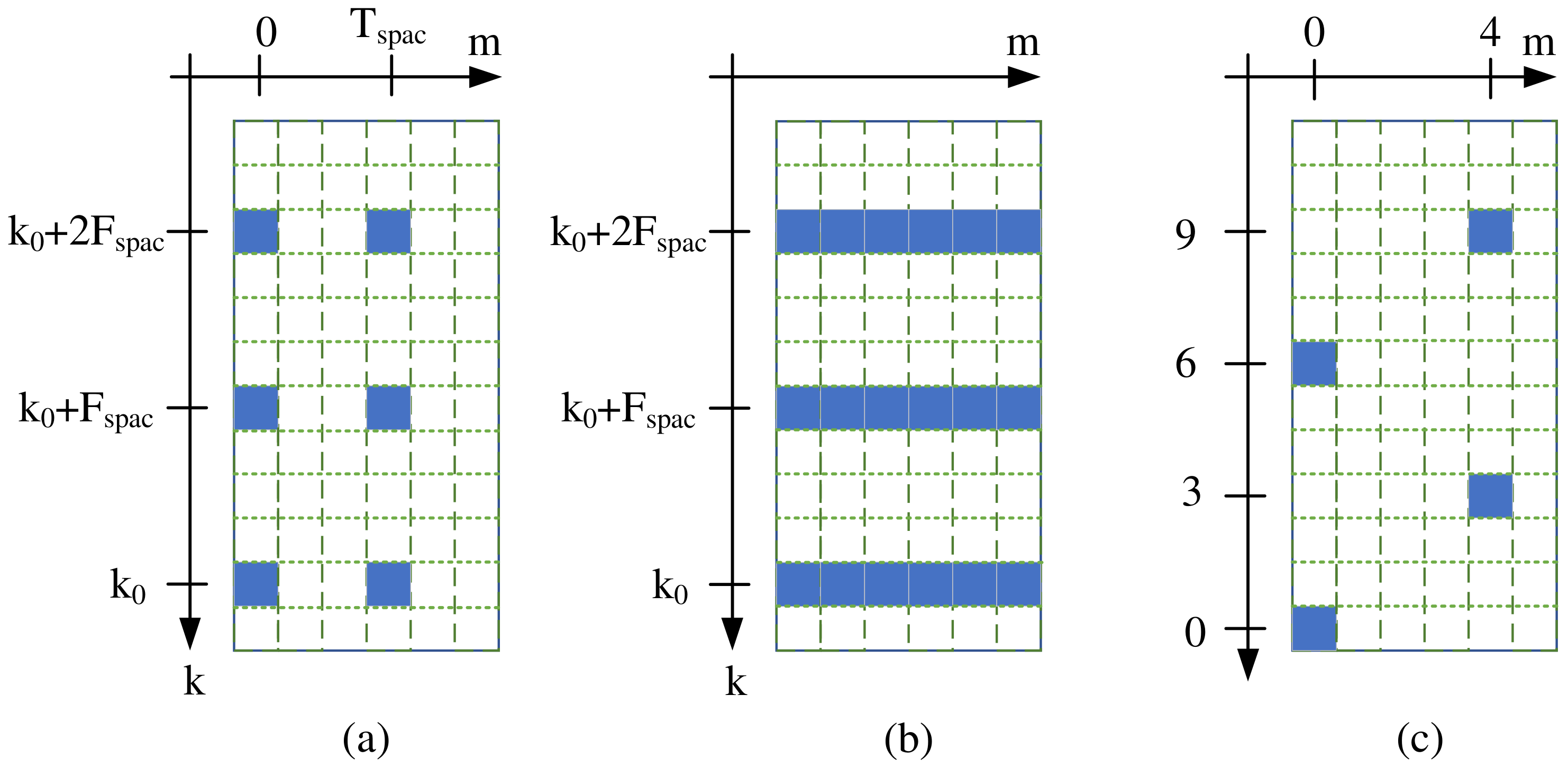
stands for the modulo operation. The number of pilots per OFDM symbol is | P | = N A 1 k 0 F spac + 1 . The proposed pilot arrangement, and the other two considered pilot patterns (comb-type and LTE CRS) are illustrated in Figure 4.
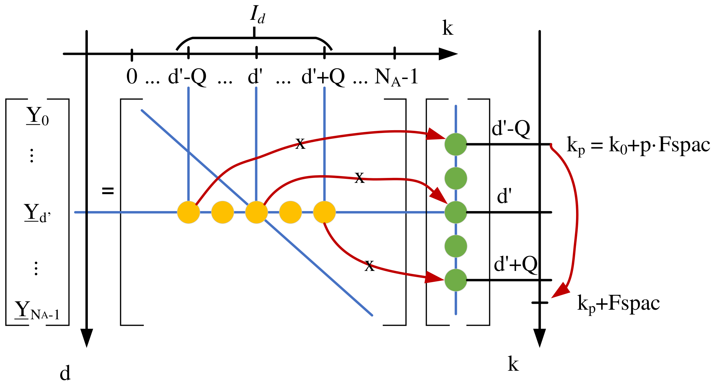
Remark 1.
The condition to obtain ICI-free samples of the channel coupling matrix according to (11) is F spac > 2 Q , and hence, the minimum pilot spacing is F spac = 2 Q + 1 .
Proof. 
Figure 5 illustrates an sketch to prove the above remark. It can be observed that, due to the banded structure of the coupling matrix, the received symbol, Y ̲ d , depends on the weighted sum of transmitted complex symbols located at sub-carriers, k I d , which is represented as the multiplication and sum of yellow and green dots. If a given pilot location, k p = k 0 + p · F spac , falls within the interval I d , then to avoid ICI, the next pilot tone at k p + F spac must be located outside I d . The case that require the greater F spac is the one where a pilot tone is placed at k p = d Q , which is the case shown in the figure. In this case to avoid ICI, the following inequality must be fulfilled: k p + F spac > d + Q , which imposes that the next pilot tone is located outside I d . Solving the above inequality leads to the ICI free condition, F spac > 2 Q . It should be noted that the value of F spac = 2 Q + 1 leads to the highest number of interference-free samples of the coupling matrix. □
If the above ICI-free condition is fulfilled, then, the received complex symbol at a given sub-carrier can be expressed as follows
Y ̲ d = B ̲ ( d , k d ) α k d + W ̲ d , if I d P = { k d } W ̲ d , if I d P =
In view of (15) it can be noticed that there can be sub-carrier locations, d, where not pilot tone is received, only noise, when the intersection of the pilot sub-carrier locations, P , and I d is the empty set. In addition, it can be observed that if I d P , then there is a single sub-carrier location, k d , that contributes to the received signal. Therefore, it is possible to obtain interference-free samples of the coupling matrix with a LS criterion as:
B ^ ̲ ( d , k d ) = Y ̲ d α k d = B ̲ ( d , k d ) + W d α k d , with k d P I d .
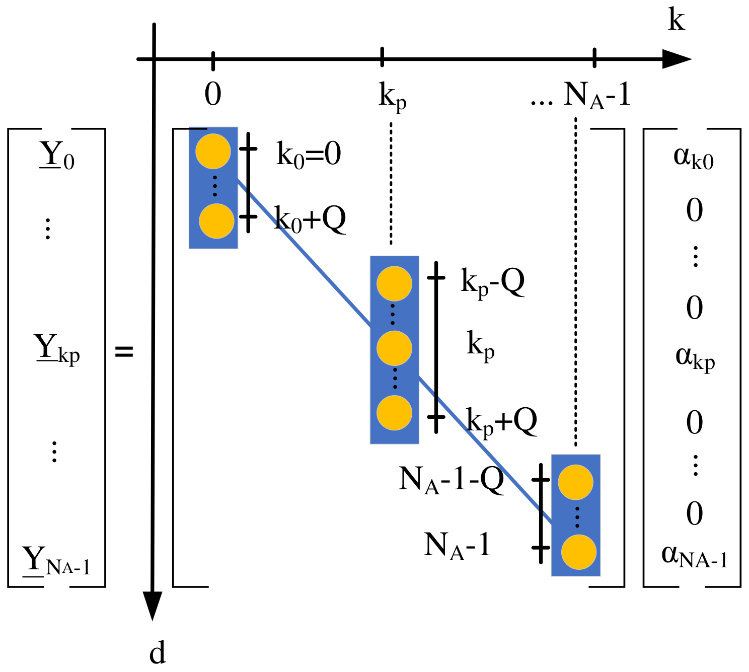
Remark 2.
Let us consider that pilot locations are defined according to P and ICI-free conditions as per Remark 1 are fulfilled, i.e., F spac > 2 Q ; then, from (16), | P | columns of B ̲ are sampled, whose locations are also defined according to P . The overall number of samples of the coupling matrix, N s , can be expressed as
N s = p = 0 N A 1 k 0 F spac min N A 1 , k p + Q max 0 , k p Q + 1
where k p = k 0 + p · F spac .
Proof. 
If ICI-free conditions are fulfilled, then, a received complex symbol on sub-carrier, d, satisfying I d P , represents a weighted noised sample of a single element of the coupling matrix, B ̲ , as per Remark 1 and (10). On the other hand, the received OFDM symbol in the frequency domain can be written as follows
Y ̲ = B ̲ 1 · X ̲ 1 + B ̲ 2 · X ̲ 2 + + B ̲ N A 1 · X ̲ N A 1 = k = 0 N A 1 B ̲ k · X ̲ k
where B ̲ k = [ b ̲ 0 , k , b ̲ 1 , k , , b ̲ N A 1 , k ] T represents the k-th column of the coupling matrix B ̲ . Since the OFDM symbol in the frequency domain, X ̲ , is a pilot symbol, then X ̲ k = 0 , k P , and thus
Y ̲ = p = 0 N A 1 k 0 F spac B ̲ k p · X ̲ k p
where k p = k 0 + p · F spac . As can be observed from (14), | P | = N A 1 k 0 F spac + 1 columns of B ̲ are sampled. The number of samples per column is determined by the sub-carrier locations of pilot tones, k p , which falls within the inteval [ 0 , N A 1 ] and by the band structure of the coupling matrix as per (7), which involves that non zero elements fulfill | d k p | Q . Hence, the set of natural numbers that represent the sampled rows, d, of the k p -th column of B ̲ can be expressed as follows
S p = d N : | d k p | Q , k [ 0 , N A 1 ] = ( a ) d N : k p Q d k p + Q , 0 d N A 1 ] = ( b ) d N : max 0 , k p Q d min N A 1 , k p + Q ]
where (b) comes from combining the two inequalities from (a). Finally, computing the number of elements of S p and summing for all the sampled columns completes the proof. □
Figure 6 illustrates an sketch of the number of elements sampled per column as determined with Remark 2. Three pilot tones are shown: one located at k 0 = 0 in the frequency domain; a second one located at k p ; and a third one located in the last sub-carrier, N A 1 . It is observed that the limits on the sub-carrier indexes affect the first and last pilot tone, reducing the number of sampled elements in the first and last sampled columns of the coupling matrix. Hence, the sampled rows of the first column range from 0 up to Q, whereas the last column has sampled rows ranging from N A 1 down to N A 1 Q . The second sampled column is different in the example of the figure. In this case, the sampled column is far from the sub-carrier edges, and the sampled rows range from k p Q up to k p + Q .
Example: To illustrate the coupling matrix estimation, let us consider the case N A = 7 , Q = 1 and k 0 = 0 . Hence, the locations of the pilots in the frequency domain are expressed as P = { 0 , 3 , 6 } and the received vector of useful sub-carriers related to an OFDM symbol with pilots can be expressed as
Y ̲ 0 Y ̲ 1 Y ̲ 2 Y ̲ 3 Y ̲ 4 Y ̲ 5 Y ̲ 6 = b ̲ 0 , 0 b ̲ 0 , 1 0 0 0 0 0 b ̲ 1 , 0 b ̲ 1 , 1 b ̲ 1 , 2 0 0 0 0 0 b ̲ 2 , 1 b ̲ 2 , 2 b ̲ 2 , 3 0 0 0 0 0 b ̲ 3 , 2 b ̲ 3 , 3 b ̲ 3 , 4 0 0 0 0 0 b ̲ 4 , 3 b ̲ 4 , 4 b ̲ 4 , 5 0 0 0 0 0 b ̲ 5 , 4 b ̲ 5 , 5 b ̲ 5 , 6 0 0 0 0 0 b ̲ 6 , 5 b ̲ 6 , 6 α 0 0 0 α 3 0 0 α 6 + W ̲ 0 W ̲ 1 W ̲ 2 W ̲ 3 W ̲ 4 W ̲ 5 W ̲ 6
According to Remark 2, we obtain N s = 7 samples of the coupling matrix for the 0-th, 3-th and 6-th columns of B ̲ : b ̲ ^ 0 , 0 = Y ̲ 0 / α 0 , b ̲ ^ 1 , 0 = Y ̲ 1 / α 0 , b ̲ ^ 2 , 3 = Y ̲ 2 / α 3 , b ̲ ^ 3 , 3 = Y ̲ 3 / α 3 , b ̲ ^ 4 , 3 = Y ̲ 4 / α 3 , b ̲ ^ 5 , 6 = Y ̲ 5 / α 6 , b ̲ ^ 6 , 6 = Y ̲ 6 / α 6 . Where the ( d , k ) -th element of B ̲ ^ is represented as b ̲ ^ d , k . It should be noticed that it is straightforward to obtain more samples of the coupling matrix if the received symbol power of guard band sub-carriers in the neighborhood of the 0-th and N A -th sub-carriers are estimated. However, the performance improvement is negligible when N A is high.
Channel interpolation: once N s samples of the coupling matrix are estimated, an interpolation of the samples is performed to estimate the coupling matrix. However, since the energy of each diagonal may be very different, instead of applying a two-dimensional (2D) interpolation method, we propose performing a 2 Q + 1 1D spline interpolation, i.e., a 1D interpolation for each of the main diagonals. With the proposed method and pilot pattern, we estimate the channel coupling matrix for every OFDM symbol with pilots. However, between OFDM pilot symbols, there are T spac data symbols. In addition, a spline interpolation in the time domain is also proposed to track the time variations of the coupling matrix.

4. LDL Based MMSE Equalization

MMSE equalization is known to outperform LS criteria since it reduces the noise enhancement related to the latter scheme. With MMSE criteria, the detected symbol vector in the frequency domain can be expressed as follows:
X ̲ = B ̲ ^ H · B ̲ ^ · B ̲ ^ H + γ 1 I N A 1 · Y ̲
where γ is the signal-to-noise ratio (SNR), and B ̲ ^ the estimated coupling matrix. Although this scheme mitigates the ICI, the matrix inversion of (22) is complex, requiring O ( N A 3 ) flops [31], where a flop represents a floating point operation (e.g., sum, product, division) of two numbers. To alleviate this burden, a low-complexity L D L H based MMSE equalization is used in this work. L D L H factorization is a variant of classical Cholesky decomposition for Hermitian positive-definite matrices that avoids the computation of square roots related to Cholesky factorization [31]. With L D L H factorization, an Hermitian positive-definite matrix, M ̲ , is expressed as L D L H , being L C N A × N A a lower unit triangular matrix, whose main diagonal elements are all 1 and D R N A × N A is a diagonal matrix. As shown in [7], L D L H factorization can be used to compute the inversion of the matrix M ̲ = B ̲ ^ · B ̲ ^ H + γ 1 I N A that appears in the right hand side of (22). The involved steps are summarized as follows, [7]:
  • Obtain the band matrix M ̲ = B ̲ ^ · B ̲ ^ H + γ 1 I N A , where B ̲ ^ is the estimated coupling matrix as per (16).
  • Factorize M ̲ according to a L D L H factorization, i.e., M ̲ = L ̲ · D ̲ · L ̲ H , being D ̲ a diagonal matrix and L ̲ a lower triangular matrix whose bandwidth is 2 Q .
  • Invert the matrix M ̲ , first, solving the system L ̲ · f ̲ = Y ̲ , which leads to f ̲ ; secondly, using f ̲ computed above and solving the system D ̲ · g ̲ = f ̲ , which leads to g ̲ ; and finally, using g ̲ computed above and solving the system L ̲ H d ̲ = g ̲ .
  • Estimate the transmitted vector, X ̲ , as X ̲ ^ = B ̲ ^ H d .
As proven in [7], the L D L H based MMSE decomposition reduces the complexity down to O ( Q 2 N A ) flops, which is a considerable reduction compared to the direct MMSE criteria of (22).

5. Numerical Results

The performance of the proposed method is assessed in terms of BER for Quadrature Phase Shift Keying (QPSK) modulation, using the ITU-Vehicular A channel [32]. The carrier frequency is 2 GHz and the mobile speed is 540 km/h. We is consider an OFDM system with sub-carrier spacing of 15 kHz and a sampling rate of 1.92 MHz. Unit transmit power is considered for all the sub-carriers, i.e., E [ | X k ( m ) | 2 ] = 1 , k [ 0 , N A 1 ] . The rest of parameters are given in Table 1. The CP length at a sampling rate of 1.92 MHz yields 4.6875 μs of guard time, which is longer than the maximum delay spread of the channel, and thus, there is no ISI.
With these parameters, the efficiency of the proposed pilot pattern as given from (9) is 2 / 3 . It can be shown that the efficiency of comb-type pattern is, η comb = 1 F spac F spac , and thus, this pattern has also an efficiency of 2 / 3 with the above simulation parameters. Finally, the LTE CRS pattern has a high efficiency, since only four sub-carriers are reserved for pilot tones within a PRB and slot [28], leading to η comb 0.952 .
To assess the performance of the proposed pilot pattern and channel estimation for ICI mitigation, its performance is compared with other techniques of small complexity. Considered pilot patterns are: (1) comb-type [33], with a frequency spacing between pilots of F spac = 3 ; (2) the LTE pilot pattern [32]; and (3) our proposed pilot pattern. With the comb and LTE patterns, it is only possible to estimate the main diagonal of the coupling matrix because of the ICI, and thus, a classical 1-tap ZF equalization is considered [7]. Finally, we also analyze the case in which the main diagonal of the coupling matrix is estimated ideally (i.e., without ICI nor any other estimation error), but the transmitted data is obtained through 1-tap ZF equalization. This case is labeled as “ H n , k ideal 1-tap ZF” to clarify the equalization does not mitigate the ICI in this case, but the channel response is obtained without ICI. The frequency domain channel interpolation in all the cases is spline [33]. However, for the time domain interpolation, the following methods are used: (1) zero-order hold (ZOH); (2) linear interpolation; and (3) spline interpolation. In case of comb-type pattern, since every OFDM symbols contain pilots, time interpolation is not performed.
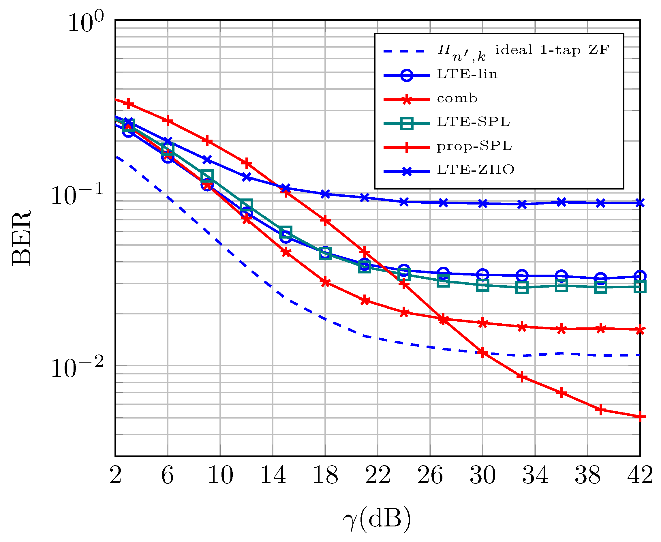
Figure 7 illustrates the performance obtained with the methods mentioned above. The legend in the figure specifies the time-interpolation method and pilot-pattern, which is defined in Table 2.
It can be observed that the proposed method with spline interpolation in the time domain achieves the best performance in the high SNR regime (prop-SPL). This is because our proposed pilot pattern and low complexity channel estimation allow obtaining the coupling matrix without ICI. In addition, the spline interpolation allows to obtain accurately the coupling matrix for the OFDM data symbols. The achieved BER in the high SNR regime is even smaller than with ideal channel estimation (ideal) of the main diagonal, since ICI mitigation is not performed in this case. The second best results (in terms of BER) are achieved by the comb type pattern (comb). This is because such a pattern offers pilots at every OFDM symbol, and hence, the channel information is not outdated for equalization purposes. However, the performance at the high SNR regime is limited by ICI in channel estimation and after equalization. The LTE pilot pattern provides a higher BER than previous pilot patters. On the other hand, ZOH interpolation provides the worst BER results whereas spline method achieves the lowest BER. This is because there is ICI in the channel estimation, the channel is outdated between OFDM symbols without pilots, and additionally, ICI is not mitigated with the equalization.
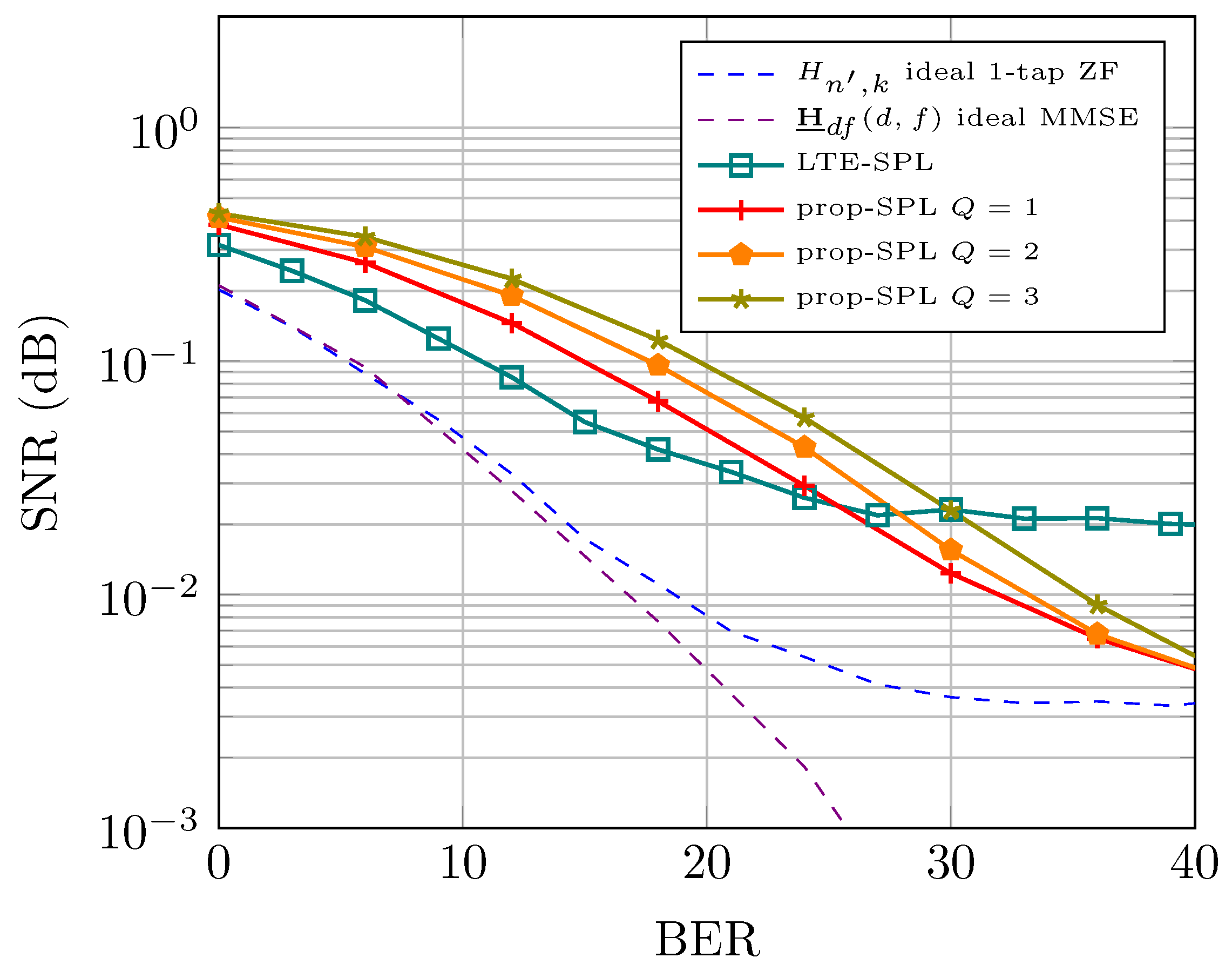
Lastly, results related to frequency-flat channel are illustrated on Figure 8 to asses the performance of the proposed technique. To illustrate the bound on achievable performance, results of the perfect (ideal) estimation of the full coupling matrix (i.e., not banded assumption), with full MMSE matrix inversion is shown with a purple dash line. As can be observed in the noise limited region (i.e., in the low SNR regime), the ideal channel estimate with 1-tap (blue dashed line) and the ideal coupling matrix estimate with MMSE equalization achieves the same performance. Nevertheless, as the SNR increases the knowledge of the coupling matrix allows perfect ICI mitigation. Besides, in this figure it is shown the proposed technique for different values of Q. It is shown that increasing Q does not improve the performance. Nevertheless, with all these values of Q BER is smaller that with the LTE pattern in the high SNR regime, which was also observed with Figure 7.

6. Conclusions

In this paper we have proposed a low-complexity pilot pattern and a frequency domain coupling matrix estimation for ICI mitigation method in OFDM systems. Our proposed channel estimation method relies on two facts: (1) the ICI generation mechanism to obtain interference-free samples of the coupling matrix; and (2) the sparse band structure of the coupling matrix to save numerical operations. Then, a LDL based MMSE equalization is proposed to remove the ICI. Simulation results have revealed that our proposed method efficiently reduces the ICI and leads to a lower BER in the high SNR regime than other schemes of reduced complexity.

Author Contributions

Conceptualization, F.J.M.-V.; methodology, F.J.M.-V.; software, F.J.M.-V.; validation, F.J.M.-V.; formal analysis, F.J.M.-V.; investigation, F.J.M.-V.; resources, G.G.; data curation, G.G.; writing—original draft preparation, F.J.M.-V.; writing—review and editing, G.G.; visualization, G.G.; supervision, G.G.; project administration, G.G.; funding acquisition, G.G. Both authors have read and agreed to the published version of the manuscript.

Funding

This work has been funded by the European Fund for Regional Development (FEDER), the Junta de Andalucía and the University of Málaga under the projects P18-RT-3175, P18-TP-3587, UMA-CEIATECH-06 and the postdoctoral grant Ref., DOC_00265 (“selección de personal investigador doctor convocado mediante Resolución de 21 de mayo de 2020”, PAIDI 2020).

Data Availability Statement

This work do not report any data.

Conflicts of Interest

The authors declare no conflict of interest.

References

  1. Hwang, T.; Yang, C.; Wu, G.; Li, S.; Ye Li, G. OFDM and Its Wireless Applications: A Survey. IEEE Trans. Veh. Technol. 2009, 58, 1673–1694. [Google Scholar] [CrossRef]
  2. Sun, S.H.; Hu, J.L.; Peng, Y.; Pan, X.M.; Zhao, L.; Fang, J. Support for vehicle-to-everything services based on LTE. IEEE Wirel. Comm. 2016, 23. [Google Scholar] [CrossRef]
  3. Martin-Vega, F.J.; Soret, B.; Aguayo-Torres, M.C.; Kovacs, I.Z.; Gomez, G. Geolocation-Based Access for Vehicular Communications: Analysis and Optimization via Stochastic Geometry. IEEE Trans. Veh. Technol. 2018, 67, 3069–3084. [Google Scholar] [CrossRef] [Green Version]
  4. Martin-Vega, F.J.; Delgado-Luque, I.M.; Blanquez-Casado, F.; Gomez, G.; Aguayo-Torres, M.C.; Entrambasaguas, J.T. LTE Performance over High Speed Railway Channel. In Proceedings of the 2013 IEEE 78th Vehicular Technology Conference (VTC Fall), Las Vegas, NV, USA, 2–5 September 2013; pp. 1–5. [Google Scholar] [CrossRef]
  5. Jeon, W.G.; Chang, K.H.; Cho, Y.S. An equalization technique for orthogonal frequency-division multiplexing systems in time-variant multipath channels. Commun. IEEE Trans. 1999, 47, 27–32. [Google Scholar] [CrossRef] [Green Version]
  6. Li, G.; Yang, H.; Cai, L.; Gui, L. A low-complexity equalization technique for OFDM system in time-variant multipath channels. In Proceedings of the 2003 IEEE 58th Vehicular Technology Conference. VTC 2003-Fall (IEEE Cat. No.03CH37484), Orlando, FL, USA, 6–9 October 2003; Volume 4, pp. 2466–2470. [Google Scholar] [CrossRef]
  7. Rugini, L.; Banelli, P.; Leus, G. Simple equalization of time-varying channels for OFDM. IEEE Commun. Lett. 2005, 9, 619–621. [Google Scholar] [CrossRef]
  8. Mostofi, Y.; Cox, D.C. ICI mitigation for pilot-aided OFDM mobile systems. IEEE Trans. Wireless Comm. 2005, 4. [Google Scholar] [CrossRef]
  9. Zhou, W.; Lam, W.H. Channel Estimation and Data Detection for OFDM Systems Over Fast-Fading and Dispersive Channels. IEEE Trans. Veh. Technol. 2010, 59. [Google Scholar] [CrossRef]
  10. Choi, Y.S.; Voltz, P.; Cassara, F. On channel estimation and detection for multicarrier signals in fast and selective Rayleigh fading channels. Commun. IEEE Trans. 2001, 49, 1375–1387. [Google Scholar] [CrossRef]
  11. Cai, X.; Giannakis, G.B. Bounding performance and suppressing intercarrier interference in wireless mobile OFDM. IEEE Trans. Commun. 2003, 51. [Google Scholar] [CrossRef] [Green Version]
  12. Molisch, A.F.; Toeltsch, M.; Vermani, S. Iterative Methods for Cancellation of Intercarrier Interference in OFDM Systems. IEEE Trans. Veh. Technol. 2007, 56, 2158–2167. [Google Scholar] [CrossRef]
  13. Chen, S.; Yang, Y. Low-Complexity MMSE-SIC Equalizer Employing LDLH Factorization for OFDM Systems Over Time-Varying Channels. IEEE Trans. Veh. Technol. 2010, 59, 4128–4131. [Google Scholar] [CrossRef]
  14. Huang, S.; Wang, J.; An, Z.; Wang, J.; Song, J. Iterative MMSE-DFE and Error Transfer for OFDM in Doubly Selective Channels. IEEE Trans. Broadcast. 2015, 61, 541–547. [Google Scholar] [CrossRef]
  15. Zhao, S.; Yan, S.; Xi, J. Bidirectional Soft-Decision Feedback Equalization for OFDM Systems. IEEE Wirel. Commun. Lett. 2020, 9, 1283–1286. [Google Scholar] [CrossRef]
  16. Schniter, P. Low-complexity equalization of OFDM in doubly selective channels. IEEE Trans. Sig. Proc. 2004, 52. [Google Scholar] [CrossRef]
  17. Rugini, L.; Banelli, P.; Leus, G. Low-Complexity Banded Equalizers for OFDM Systems in Doppler Spread Channels. EURASIP J. Adv. Signal Process 2006, 9, 1283–1286. [Google Scholar] [CrossRef] [Green Version]
  18. Das, S.; Schniter, P. Max-SINR ISI/ICI-Shaping Multicarrier Communication Over the Doubly Dispersive Channel. IEEE Trans. Signal Process. 2007, 55, 5782–5795. [Google Scholar] [CrossRef] [Green Version]
  19. Vlachos, E.; Lalos, A.S.; Berberidis, K.; Thompson, J. Adaptive Windowing for ICI Mitigation in Vehicular Communications. IEEE Wirel. Commun. Lett. 2018, 7, 974–977. [Google Scholar] [CrossRef]
  20. Wu, T.W.; Chung, C.D. Correlatively Precoded OFDM With Reduced PAPR. IEEE Trans. Veh. Technol. 2016, 65, 1409–1419. [Google Scholar] [CrossRef]
  21. Ryu, H.G.; Li, Y.; Park, J.S. An improved ICI reduction method in OFDM communication system. IEEE Trans. Broadcast. 2005, 51, 395–400. [Google Scholar] [CrossRef]
  22. Chang, M.X. A Novel Algorithm of Inter-Subchannel Interference Self-Cancellation for OFDM Systems. IEEE Trans. Wirel. Commun. 2007, 6, 2881–2893. [Google Scholar] [CrossRef]
  23. Lin, K.Y.; Lin, H.P.; Tseng, M.C. An Equivalent Channel Time Variation Mitigation Schefme for ICI Reduction in High-Mobility OFDM Systems. IEEE Trans. Broadcast. 2012, 58, 472–479. [Google Scholar] [CrossRef]
  24. Ma, C.Y.; Liu, S.W.; Huang, C.C. Low-Complexity ICI Suppression Methods Utilizing Cyclic Prefix for OFDM Systems in High-Mobility Fading Channels. IEEE Trans. Veh. Technol. 2014, 63, 718–730. [Google Scholar] [CrossRef]
  25. Cheon, H.; Hong, D. Effect of imperfect channel information in OFDM-based WLAN. Electron. Lett. 2002, 38. [Google Scholar] [CrossRef]
  26. Han, S.H.; Lee, J.H. An overview of peak-to-average power ratio reduction techniques for multicarrier transmission. IEEE Wirel. Commun. 2005, 12, 56–65. [Google Scholar] [CrossRef]
  27. Zhang, W.; Xia, X.G.; Ching, P.C. Optimal Training and Pilot Pattern Design for OFDM Systems in Rayleigh Fading. IEEE Trans. Broadcast. 2006, 52, 505–514. [Google Scholar] [CrossRef]
  28. European Telecommunications Standards Institute. LTE; Evolved Universal Terrestrial Radio Access (E-UTRA); Physical Channels and Modulation; (3GPP TS 36.211 Version 16.4.0 Release 16): Technical Specification; Sophia-Antipolis: Valbonne, France, 2021. [Google Scholar]
  29. Morelli, M.; Mengali, U. A comparison of pilot-aided channel estimation methods for OFDM systems. IEEE Trans. Signal Process. 2001, 49, 3065–3073. [Google Scholar] [CrossRef]
  30. van de Beek, J.; Sandell, M.; Borjesson, P. ML estimation of time and frequency offset in OFDM systems. Signal Process. IEEE Trans. 1997, 45, 1800–1805. [Google Scholar] [CrossRef] [Green Version]
  31. Golub, G.H.; Van Loan, C.F. Matrix Computations, 3rd ed.; The Johns Hopkins University Press: Baltimore, MD, USA, 1996. [Google Scholar]
  32. Sesia, S.; Toufik, I.; Baker, M. LTE-The UMTS Long Term Evolution: From Theory to Practice, 2nd ed.; Wiley: Hoboken, NJ, USA, 2011. [Google Scholar]
  33. Coleri, S.; Ergen, M.; Puri, A. Channel estimation techniques based on pilot arrangement in OFDM systems. IEEE Trans. Broadcast. 2002, 48. [Google Scholar] [CrossRef] [Green Version]
Figure 1. Functional blocks of the simulator. Blocks related to the transmitter are drawn in blue whereas blocks related to the receiver are drawn in green. Blocks related to Bit Error Rate (BER) metric computation and wireless channel are in orange.
Electronics 10 01404 g001
Figure 2. Block diagram of the Orthogonal Frequency Division Multiple (OFDM) modulator.
Electronics 10 01404 g002
Figure 3. Ideal coupling matrix for a ITU Vehicular A channel model with v = 500 km/h at a carrier frequency of 2 GHz using FFTs of 128 points and 15 kHz of sub-carrier spacing.
Electronics 10 01404 g003
Figure 4. Pilot patters: (a) proposed pilot pattern; (b) comb-type; (c) Long Term Evolution Cell Specific Reference Signal (LTE CRS) pilot pattern.
Electronics 10 01404 g004
Figure 5. Sketch of proof for Remark 1: minimum spacing between pilot tones to avoid Inter-Carrier Interference (ICI).
Electronics 10 01404 g005
Figure 6. Sketch of proof for Remark 2: number of samples of the coupling matrix.
Electronics 10 01404 g006
Figure 7. BER versus Signal-to-Noise Ratio (SNR) under ITU-Vehicular A channel model for different channel estimation and equalization techniques.
Electronics 10 01404 g007
Figure 8. BER versus SNR under frequency-flat (single path) channel with Jakes Doppler spectrum for different channel estimation and equalization techniques.
Electronics 10 01404 g008
Table 1. Simulation parameters.
ParameterDescriptionValue
NFFT size128
N A Number of active sub-carriers72
GCP length9
Δ f Sub-carrier spacing15 kHz
f s Sampling rate 1.92 MHz
α k , k P Pilot tone amplitude1
E [ | X k ( m ) | 2 ] , m M Power of data symbols1
-Modulation orderQPSK
k 0 Pilot sub-carrier offset (prop. pattern)0
QICI spreading factor1
T spac Symbol pilot spacing (prop. pattern)3
F spac Freq. pilot spacing (prop. and comb patt.)3
f c Carrier frequency2 GHz
vVelocity540 km/h
f d Normalized Doppler frequency 0.067
-Doppler SpectrumJakes
Table 2. Simulation parameters.
LegendPilot PatternTime InterpolationEqualization
H n , k ideal 1-tap ZFnonenoneZF
H ̲ d f ( d , f ) ideal MMSEnonenoneMMSE
combcomb-typenoneZF
LTE-ZOHLTEZOHZF
LTE-LINLTElinearZF
LTE-SPLLTEsplineZF
prop-SLPprop.spline L D L H -MMSE
Publisher’s Note: MDPI stays neutral with regard to jurisdictional claims in published maps and institutional affiliations.

