Article

Novel Control Strategy for Enhancing Microgrid Operation Connected to Photovoltaic Generation and Energy Storage Systems

1
Department of Electrical Power and Machines, Faculty of Engineering, Ain-Shams University, Cairo 11517, Egypt
2
Faculty of Engineering and Technology, Future University in Egypt, Cairo 11835, Egypt
3
Department of Electrical Engineering and Automation, School of Electrical Engineering, Aalto University, FI-00076 Espoo, Finland
4
Department of Electrical Engineering, Faculty of Engineering, Aswan University, Aswan 81542, Egypt
5
Department of Electrical Engineering, Faculty of Engineering at Shoubra, Benha University, Cairo 11629, Egypt
*
Author to whom correspondence should be addressed.
Electronics 2021, 10(11), 1261; https://doi.org/10.3390/electronics10111261
Submission received: 17 April 2021 / Revised: 16 May 2021 / Accepted: 19 May 2021 / Published: 25 May 2021
(This article belongs to the Special Issue Theory and Applications of Fuzzy Systems and Neural Networks)

Abstract

:
Recently, the penetration of energy storage systems and photovoltaics has been significantly expanded worldwide. In this regard, this paper presents the enhanced operation and control of DC microgrid systems, which are based on photovoltaic modules, battery storage systems, and DC load. DC–DC and DC–AC converters are coordinated and controlled to achieve DC voltage stability in the microgrid. To achieve such an ambitious target, the system is widely operated in two different modes: stand-alone and grid-connected modes. The novel control strategy enables maximum power generation from the photovoltaic system across different techniques for operating the microgrid. Six different cases are simulated and analyzed using the MATLAB/Simulink platform while varying irradiance levels and consequently varying photovoltaic generation. The proposed system achieves voltage and power stability at different load demands. It is illustrated that the grid-tied mode of operation regulated by voltage source converter control offers more stability than the islanded mode. In general, the proposed battery converter control introduces a stable operation and regulated DC voltage but with few voltage spikes. The merit of the integrated DC microgrid with batteries is to attain further flexibility and reliability through balancing power demand and generation. The simulation results also show the system can operate properly in normal or abnormal cases, thanks to the proposed control strategy, which can regulate the voltage stability of the DC bus in the microgrid with energy storage systems and photovoltaics.

1. Introduction

Global warming and carbon dioxide emissions, attributed to traditionally used energy sources, have become severe issues in the world for the last few years. Hence, the improvement of renewable energy sources (RES) has gained great research interest to mitigate and reduce such risks. Some RES, such as photovoltaic cells or wind turbines, are well-developed since they are clean and cost-effective [1,2,3]. However, other sources such as fuel cells and biomass are still in their growth stage [4].
Microgrid systems, which are classified as AC or DC microgrids, could merge RES with household and industrial loads [5,6,7]. The differences between both types of microgrids as well as their advantages are deeply discussed in the literature [8,9]. In fact, power electronic devices (PED) have recently become a must in grid integration, since photovoltaic systems output DC power while wind systems’ output is in the form of variable frequency/voltage AC power. Additionally, some modern electronic loads, such as computers and plug-in hybrid electric vehicles, and even traditional AC loads such as induction motors, require DC power when driven by a variable-speed drive. Consequently, DC microgrids have been proven as one of the most efficient and cost-effective systems in the integration of RES with loads, as they decrease the AC-DC and DC-AC power conversion stages compared to AC microgrids [10,11]. Machine learning and artificial intelligence have shown promising performance in different electrical engineering applications [12,13,14,15,16] as well as power system components, e.g., power transformers and high voltage transmission lines [17,18,19,20,21,22,23]. Figure 1 illustrates the microgrid components in which the load and the diesel generator along with the wind turbines are connected to the AC side. In turn, PV units and battery energy storage systems (BESS) are tied to the DC side which is connected to the AC side by DC/AC inverter.
Among different RES merged with DC microgrids, photovoltaic (PV) cells are considered clean and scalable. PV microgrids operate in islanded mode to supply power to a small community or are tied to a grid as a distributed generator. However, a PV system is an intermittent source of energy as it depends on weather conditions and whether the sun is shining [24,25]. To overcome such drawbacks, energy storage systems (ESS) such as batteries or supercapacitors should be applied in the microgrid to attain smooth and reliable power generation from the PV system. ESS is charged during sunlight hours when PV power exceeds load demand, while during peak times, shortages of power generation, or unstable generation of PV, ESS discharge their energy [26,27,28]. The PV systems are widely operated in two modes of operation: stand-alone and grid-connected modes [29,30,31,32,33]. During the stand-alone mode, ESS compensates for the shortage of power generated by the PV modules, and if the stored power was insufficient, the system undergoes load shedding to meet the system requirements [34]. On the other hand, the utility grid manages to achieve power balance and DC voltage stability in the grid-tied mode [35]. Different strategies have been proposed for the control of DC microgrids. Standalone PV system control with a battery storage system through a bidirectional buck-boost converter is discussed in [36], with the aim of maintaining DC voltage stability. A control strategy for the integrated DC microgrid under variable load demand and different insolation levels through islanded mode and grid-connected mode is demonstrated in [37]. A hybrid AC/DC microgrid control that can manage and regulate power flow with both DC and AC buses in grid-connected and islanded modes is presented in [38]. Some limitations on battery discharge and grid power transfer are simulated in [39].
In this paper, the integration of a PV system, a battery storage system, and DC load in a DC microgrid is simulated using the Simscape power systems toolbox, MATLAB/Simulink (2018b, MathWorks Inc., Natick, MA, USA) platform. The effects of various controllers on the voltage stability of the system is observed during different solar irradiation cases, load demands, batteries, and grid power transfers. In particular, DC–DC and DC–AC converters are managed to achieve DC voltage stability in the microgrid while the system is operated in two practical modes: (1) stand-alone and (2) grid-connected. The novelty of this work is that different operating techniques of the microgrid are simulated using the traditional Direct-Quadrature (DQ) control strategy in cooperation with the voltage current controllers, where the updated voltage-oriented current control regulates DC voltage and ensures power balance between sources and load. Additionally, maximum power generation from the photovoltaic system can be attained by the novel control strategy across different techniques for operating the microgrid. The proposed battery converter control can introduce a stable operation and regulate DC voltage. The advantage of the integrated DC microgrid with batteries is that it accomplishes better flexibility and reliability while balancing power demand and generation. Accordingly, the microgrid can perform properly in both normal and sudden variation cases, thanks to the proposed control strategy that improves the voltage stability of the DC bus interconnected with energy storage systems and photovoltaics.
The rest of the paper is organized as follows: The proposed PV-based DC microgrid structure and controller modeling are analyzed in Section 2. Simulation results are presented in Section 3. Finally, the conclusions drawn from the results are presented in Section 4.

2. System Configuration and Modeling

The configuration of the proposed PV microgrid includes (1) PV arrays with the DC–DC boost converter and maximum power point tracking (MPPT), (2) a battery energy storage system (BESS) with DC–DC bidirectional buck–boost converters, (3) a voltage source converter (VSC) in the case of the grid-tied system. The utility grid is represented as the three-phase ideal voltage source. The BESS is used to maintain the power balance between PV power generation and the load demand in the islanded mode. A typical radial DC microgrid configuration is shown in Figure 2. Different microgrid structures are discussed in references [35,40,41].
The PV based microgrid is controlled through a MPPT controller, a BESS local control unit that charge-discharges the battery bank based on the operation mode and a VSC controller. Table 1 introduces comparative analysis of various VSC control strategies.

2.1. Photovoltaic System

The main source of power supply in the DC microgrid is the photovoltaic system which is controlled to operate at the maximum power point (MPP). Consequently, PV cell model representation has become an important field of study. Although there are several equivalent circuits to represent the PV array, the typical and most commonly used one is the single-diode circuit as it is characterized by its simplicity and accuracy. It is known also as the five-parameter model. The circuit shown in Figure 3 combines a photo-generated controlled current source parallel to a single diode, series resistance, and parallel resistance representing power losses [46].
The photovoltaic cell is constructed based on P–N junctions, which are made from semiconductor materials. Silicon is dominantly used due to its abundance, non-toxicity, high and stable cell efficiencies [47]. The I–V characteristic of the solar cell is given by implicit and nonlinear equations as follows:
I P V = I g I d V P V + R s I P V R p
I d = I o exp q ( V P V + R s I P V ) n K T 1
V D = V P V + R s I P V
In an array, PV modules are connected in series and in parallel. A group of PV cells is connected together in series to form a string, then the group of strings is connected in parallel to form an array. The current-voltage relationship of the array is affected by these connections as given by [48]:
I P V = N P I g N P I d V P V + N s N p R s I P V N s N p R p
I d = I o exp q ( V P V + N s N p R s I P V ) N s n K T 1
where q   is the electronic charge, K   is the Boltzmann constant, n is the ideality factor, T   is the cell temperature,   I g represents a current source created by sunlight known as a photocurrent, i.e., irradiance current, I o is the diode saturation current, R S is the series resistance, R P   is the shunt resistance, N s is the number of cells connected in series in the array, N p is the number of strings in parallel, I P V and V P V are the current and voltage outputs of the PV array, respectively.
PV systems deliver varying power depending on solar temperature and irradiation. As a result, MPPT should take place to optimize the power that can be delivered by PV cells. MPP differs according to light intensity and cell temperature and isn’t a particular operating point on the P–V curve. Hence, a control technique is applied to the PV array with a boost converter to control its duty cycle to drive the system to operate at its optimal value [49].
There are various methods to implement MPPT tracking [50]. The most common methods are incremental conductance (IC) and perturb and observe (P&O). The IC technique has the advantage of a fast response to changes in irradiation and temperature. Moreover, it can determine when MPPT reaches the MPP during these changes while P&O oscillates around the MPP [51,52]. IC is implemented based on the study of the P–V curve; the MPP is reached when d P/ d V = 0. The equations of the IC method are [53]:
P = V I
P V = I V V + V I V = I + V I V
d I d V = I V        a t   M P P
d I d V > I V        L e f t   o f   M P P
d I d V < I V        R i g h t   o f   M P P
As shown in the previous equations, the output incremental conductance equals the negative of the instantaneous output conductance at the MPP in the IC method. MPPT controls the duty cycle of the DC–DC boost converter to reach the condition d I / d V = I / V . The flow chart of IC MPPT in Figure 4 shows the algorithm. If (9) is satisfied, the duty cycle of the converter needs to be increased in order to increase the operating voltage to attain MPP, and vice versa if (10) is satisfied.

2.2. Battery Energy Storage System

Solar power generation may exceed or fall behind load demand. In addition, intermittency of PV power leads to the need for ESS to store the surplus power, supply power when there are deficits, and maintain grid stability during fluctuations resulting from changes in weather conditions like cloud shadows on the PV array. The storage module consists of a Lithium-ion battery bank and a bidirectional DC–DC buck–boost converter. Lithium-ion batteries have high energy capacity, low maintenance needs, and a robust life cycle. The control of the bidirectional buck–boost converter regulates charging and discharging of the BESS based on DC bus voltage, so the control is designed in bus monitoring (BM) mode [54]. The battery model shown in Figure 5 can be modeled through a general dynamic model that can be described by the equations [55]:
V b a t t = E g i b a t t R b a t t
E g = E g o K Q Q i b a t t d t + A e B i b a t t d t
where,
  • E g = no-load voltage (V)
  • E g o = battery constant voltage (V)
  • K = polarization voltage (V)
  • Q = maximum battery capacity (Ah)
  • i b a t t d t = actual battery charge (Ah)
  • A = exponential zone amplitude (V)
  • B = exponential zone time constant inverse (Ah)−1
  • V b a t t = battery output voltage (V)
  • R b a t t = internal resistance (resistance that the battery opposes to the flow of energy) (Ω)
  • i b a t t = battery current (A)
Figure 5. Equivalent circuit of battery.
Electronics 10 01261 g005
The storage local control unit adjusts battery current to control charge and discharge of the battery by providing duty cycle to the converter as introduced in Figure 6. Hence, DC bus voltage remains stable.

2.3. Grid and Voltage Source Converter

The grid circuit is composed of a three-phase AC voltage source, an inductive-capacitive-inductive (LCL) filter which is responsible for reducing voltage and current switching harmonics, and a converter. Although the capacitive–inductive–capacitive (CLC) filter has the merits of reduced cost and size, it is commonly used with low current equipment. The used filter in the architecture is LCL, which has better capability in reducing total harmonic distortion compared to other filters, limits higher frequency current inflow, keeps the current harmonics in and around the operating frequency within the restricted limits, and could be designed to have a high dynamic response to meet the fast dynamics in power grids existing in Egypt. VSC is controlled to maintain the stability of the system and DC bus. A grid-connected VSC Control loop is used to adjust the DC voltage and generate pulse width modulation signals as shown in Figure 7 [56].
The control strategy used with the VSC is vector control, also known as voltage-oriented control. This scheme is characterized by its high dynamic performance. There are two control loops, the outer loop is the voltage control loop for regulating the DC voltage, and the inner one is the current control loop which regulates direct axis current I d and quadrature axis current I q . VSC can control active and reactive powers independently. The direct axis component is responsible for controlling DC link voltage since the output from the outer voltage control loop is I d   r e f . However, the quadrature axis component is responsible for controlling the reactive power transfer where I q is set to zero, as there is no reactive power. The outputs of the current control loop, V d   r e f and V q   r e f , are converted to a three-phase voltage reference, then the pulse width modulator (PWM) generates gate pulses to control the converter so that DC voltage is regulated [57].

3. Results and Discussions

The integration of PV microgrids with battery storage is simulated using the MATLAB/Simulink platform. The parameters of the microgrid, PV array, battery, and DC load are provided in Table 2. The PV array in the grid-tied DC microgrid is composed of 47 parallel strings each consists of 10 series modules. PV systems have higher capital costs per unit and much lower operating costs than traditional fossil-based electrical resources. However, progress in the PV industry continues, with reasonable scope for further cost reductions in the near future. As a result, PV panels can be manufactured at lower costs and can generate energy at higher efficiencies, reducing production costs per watt. The simulation sampling time is 10 µs, which is suitable to the switching frequency of the control components, so as to increase the accuracy of the controlling devices. Note that sampling time and hence sampling frequency is suitable for the switching frequency of the control components. Additionally, digital signal processors (DSP) that are used in power system applications in Egypt have switching frequency ranges from 70 to 160 kHz. The used time step in the model is variable. PWM is of an asymmetrical type. First, the microgrid is tested at constant load demand through different PV irradiance in different cases. Then, it is tested for different load demands.

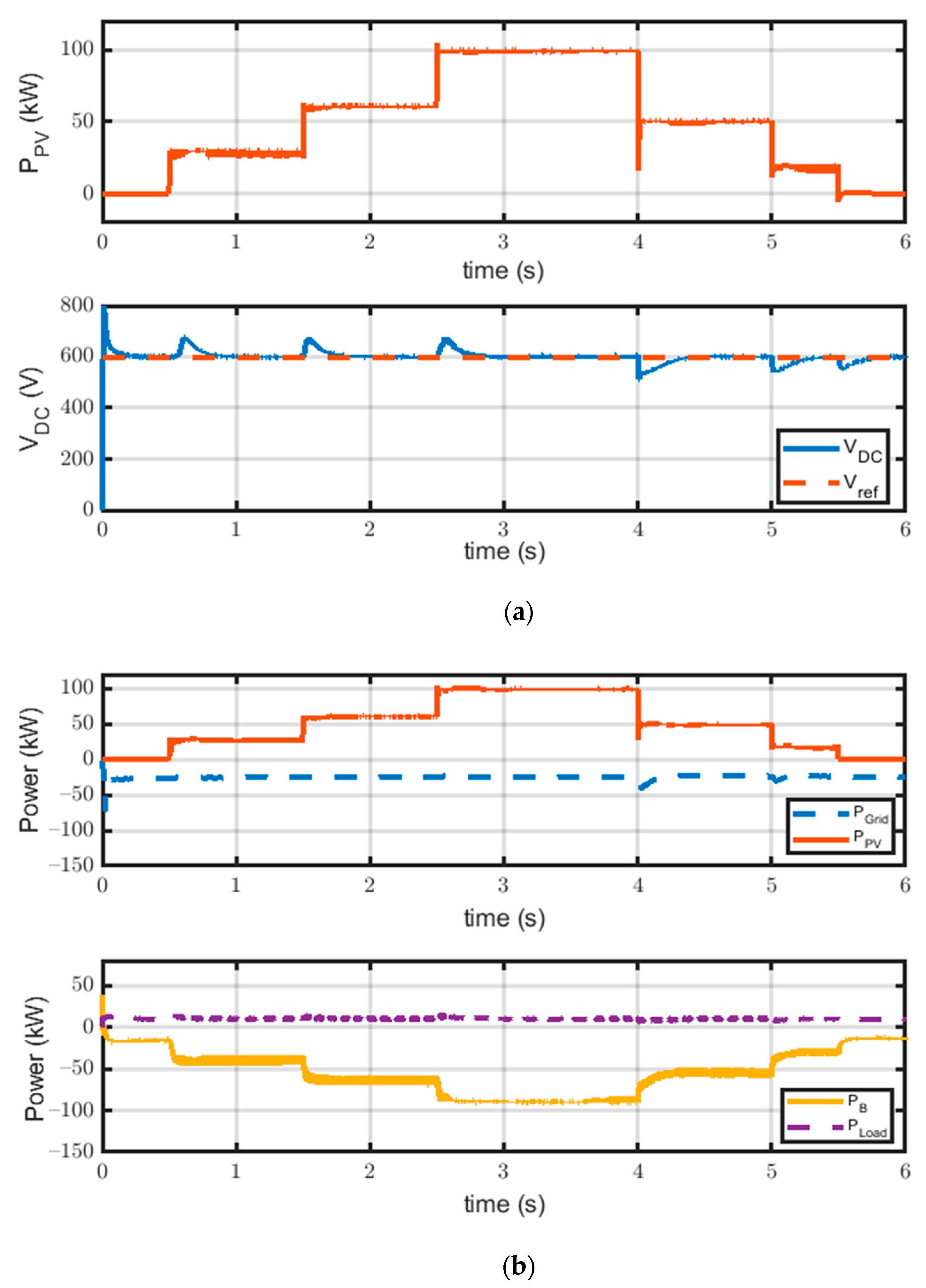
3.1. Grid-Tied PV Microgrid

In this simulation, the PV microgrid is connected to the utility grid and VSC control is responsible for regulating DC load and DC bus voltage. When the PV generation is more than the load demand in cases of high irradiance, surplus power goes to the grid. However, when it is below load demand, the utility grid supplies the deficiency in power generated by the PV system to the load. The load consumes constant power in all irradiance changes. At instants of sudden changes in irradiance, DC bus voltage is maintained within the permissible limits, ±5%, consequently, load voltage remains in the allowed range which is (600 V ± 30 V). However, there are tiny fluctuations and sudden drops and rises in irradiance for both the DC bus voltage and power provided to the DC load. Therefore, voltage stability is controlled by grid VSC as shown in Figure 8.

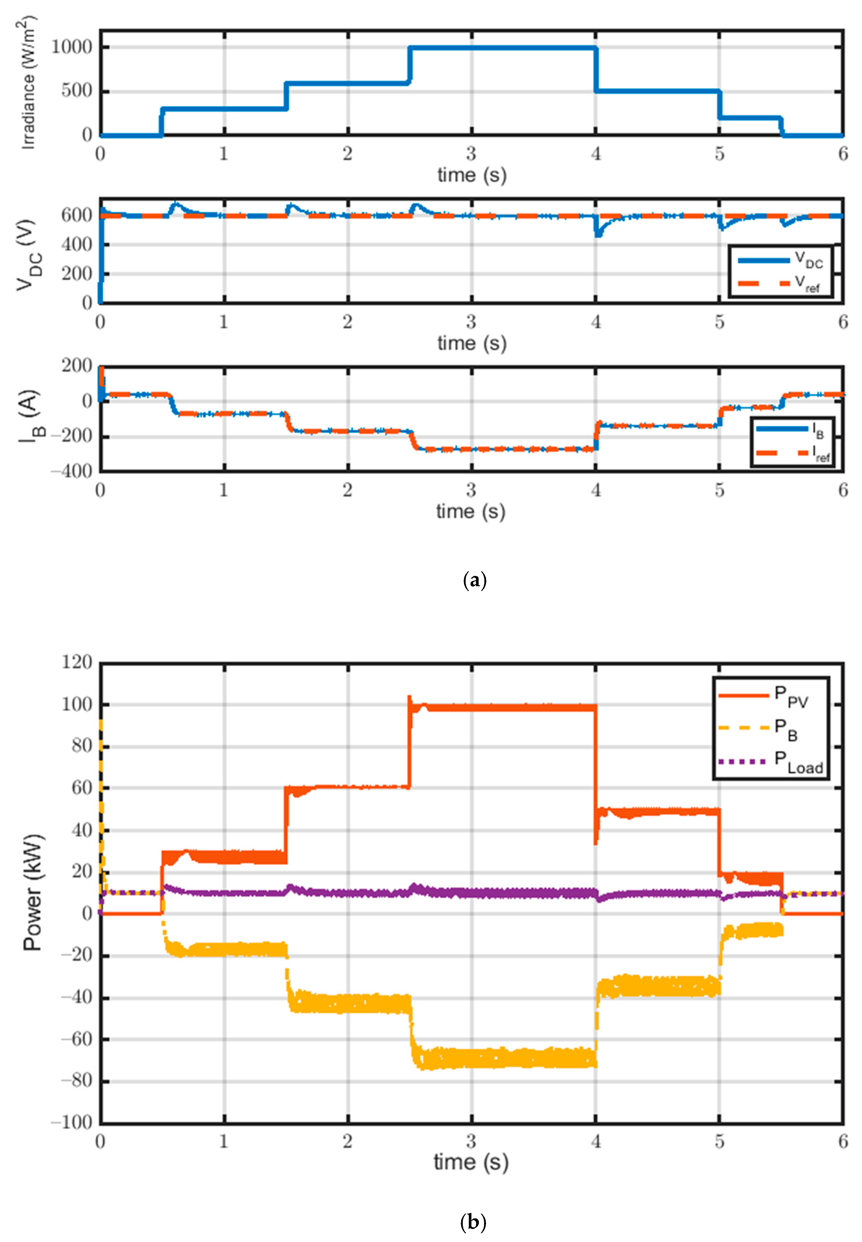
3.2. Islanded PV Microgrid

In this simulation, the PV microgrid is disconnected from the utility grid, and the battery with the bidirectional converter control becomes responsible for regulating DC load voltage. The battery discharges to maintain DC load voltage stability and to supply power in case of low power generation by the PV system. When PV power generation increases above the load demand, the battery starts charging from the excess power generated by the PV system as illustrated in Figure 9. Voltage spikes and sags are observed at sudden changes of irradiance, as a result of the fast change of battery current, which causes a voltage increase or decrease due to the flow of momentary current through the parallel diode during switching operations of converter switches.

3.3. Grid-Tied PV Microgrid with Constant Grid Power

The constant power mode of the utility grid is presented in this case, during which the influence of the microgrid on the utility power system is reduced. Figure 10 shows that the grid supplies constant power to the microgrid by controlling the direct current i d to track reference positive current i d * . Hence, DC voltage is not controlled using VSC control. Therefore, the battery converter regulates DC load voltage and deals with the power generated from the PV module to make the battery charge during excess power generation from the PV system and discharge during PV low power generation. The presence of voltage fluctuations at every sudden change in irradiance level is shown in this case, as with the islanded mode of operation response, because here the battery converter controller is also responsible for DC voltage regulation but voltage is quickly established to track the reference DC voltage. Furthermore, the battery bank responds to changes in the power imbalance between power generation and load demand, thus supplying almost stable power to the load.

3.4. Grid-Tied PV Microgrid with Constant Battery Discharge

Figure 11 shows the battery discharge by constant rate through controlling battery current i B to positive reference current i B * . Battery power is the constant positive power and grid powDer transfer to load is regulated by VSC control. It is also observed that DC-bus power is not affected by the variations.

3.5. Islanded PV Microgrid with Different Load Demands

For this case, the bidirectional converter is responsible for controlling the charge and discharge of the battery. The power transfer illustrated in Figure 12 shows the response of the DC microgrid in islanded mode with different load demands. It is observed that at instants t = 2 s and t = 4 s the load power is suddenly increased by 10 kW to evaluate the performance of the system at different operating conditions. Therefore, at t = 2 s the load is suddenly increased but PV power generation still exceeds the load demand, so the battery continues to be charged; battery power is negative, therefore, the converter is in buck mode but its power decreases as the load consumes the difference in power. At t = 4 s, the load demand increases by 10 kW, and PV power generation is still higher than demand, so the battery continues to be charged while at t = 5 s, PV generation is decreased past load demand, consequently, the battery responds to meet load demand, where the bidirectional converter is put into boost mode. The system maintains its stability and supply load at different load changes using the control strategy of a battery bidirectional converter. The settling time at transient moments is slightly high but the system quickly restores its stability. When the battery is full, the PV system only supplies the load with no extra energy. In other words, the PV system does not operate at maximum power point but will operate according to load demand.

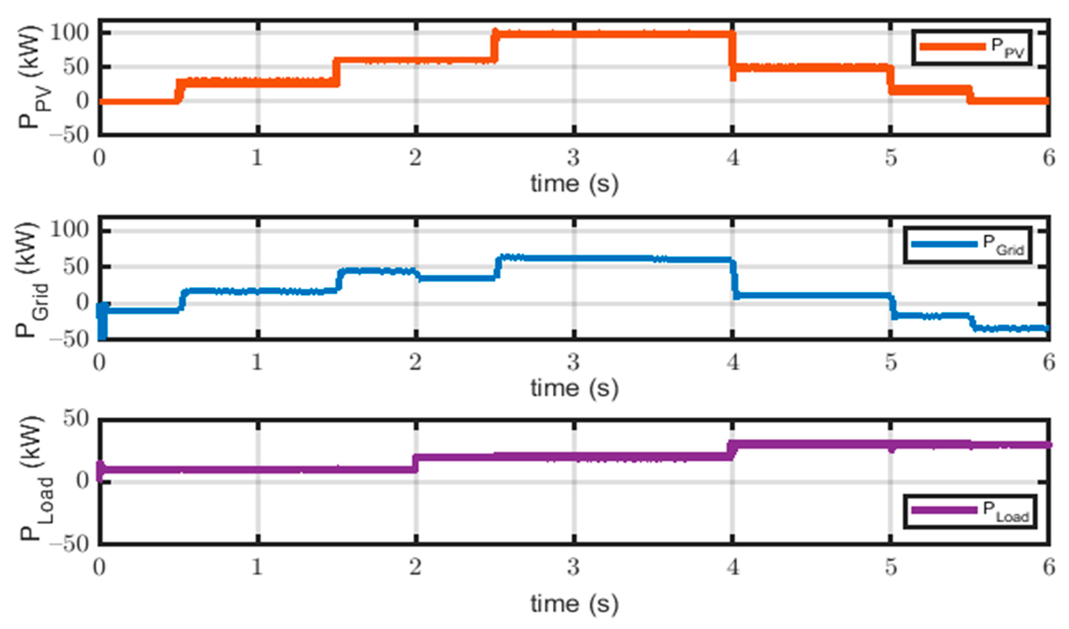
3.6. Grid-Tied PV Microgrid with Different Load Demands

For the different load demands and variable PV power generation due to different irradiance levels, the utility grid is responsible for supplying the load when demand is increased over PV generation in the grid-tied mode of operation as shown in Figure 13. It is observed that when irradiance level is low during the night or when it is cloudy, grid power is negative to supply the load instead of the PV system. Hence, the grid VSC control is the main controller in this case. Furthermore, power stability is enhanced for the system when tied to the grid rather than in the islanded mode.

4. Conclusions

This paper presents the enhanced operation of DC microgrid with PV generation as RES and battery as the energy storage system. The grid is connected and disconnected according to the mode of operation. Local control units of VSC and battery bidirectional converters are used to attain the required references for the different cases of simulation of the DC microgrid. The system is simulated for 6 s and the results are analyzed for each case. Results show that an integrated DC microgrid with batteries achieves more flexibility and reliability in the system by balancing power demand and generation. The stability of the DC microgrid is studied to test the reliability of the system during different modes of operations and different load changes. Through the simulation, discussion and results, it can be concluded that whether the system operates in normal cases or abnormal cases, different control strategies can regulate stable DC bus voltage. Additionally, it is observed that the grid-tied mode of operation regulated by VSC control offers more stability than islanded mode. However, battery converter control introduced a stable operation and regulated DC voltage but with a few voltage spikes.

Author Contributions

All authors have contributed to the preparation of this manuscript. D.E. and M.E. designed the idea strategy, wrote the draft manuscript, and studied the data. M.M.F.D. and K.M. wrote the manuscript and designed some figures related to microgrids and introduction. Finally, A.Y.A. and M.L. reviewed, edited, and supported different improvements in the manuscript. All authors have read and agreed to the published version of the manuscript.

Funding

This research was supported by the Department of Electrical Engineering and Automation, School of Electrical Engineering, Aalto University, Espoo, Finland.

Data Availability Statement

The data presented in this study are available on request from the corresponding author.

Conflicts of Interest

The authors declare no conflict of interest.

References

  1. Lee, D.; Lee, D.; Jang, H.; Joo, S.-K. Backup Capacity Planning Considering Short-Term Variability of Renewable Energy Resources in a Power System. Electronics 2021, 10, 709. [Google Scholar] [CrossRef]
  2. Ali, E.; El-Sehiemy, R.; El-Ela, A.A.; Mahmoud, K.; Lehtonen, M.; Darwish, M. An Effective Bi-Stage Method for Renewable Energy Sources Integration into Unbalanced Distribution Systems Considering Uncertainty. Processes 2021, 9, 471. [Google Scholar] [CrossRef]
  3. Elsisi, M.; Tran, M.-Q.; Mahmoud, K.; Lehtonen, M.; Darwish, M.M.F. Robust Design of ANFIS-Based Blade Pitch Controller for Wind Energy Conversion Systems Against Wind Speed Fluctuations. IEEE Access 2021, 9, 37894–37904. [Google Scholar] [CrossRef]
  4. Grumm, F.; Schumann, M.; Cosse, C.; Plenz, M.; Lücken, A.; Schulz, D. Short Circuit Characteristics of PEM Fuel Cells for Grid Integration Applications. Electronics 2020, 9, 602. [Google Scholar] [CrossRef] [Green Version]
  5. Zhou, J.; Sun, H.; Xu, Y.; Han, R.; Yi, Z.; Wang, L.; Guerrero, J.M. Distributed Power Sharing Control for Islanded Single-/Three-Phase Microgrids with Admissible Voltage and Energy Storage Constraints. IEEE Trans. Smart Grid 2021, 1, 1. [Google Scholar] [CrossRef]
  6. Hirsch, A.; Parag, Y.; Guerrero, J. Microgrids: A review of technologies, key drivers, and outstanding issues. Renew. Sustain. Energy Rev. 2018, 90, 402–411. [Google Scholar] [CrossRef]
  7. Lv, J.; Wang, X.; Wang, G.; Song, Y. Research on Control Strategy of Isolated DC Microgrid Based on SOC of Energy Storage System. Electronics 2021, 10, 834. [Google Scholar] [CrossRef]
  8. Guerrero, J.M.; Chandorkar, M.; Lee, T.-L.; Loh, P.C. Advanced Control Architectures for Intelligent Microgrids—Part I: Decentralized and Hierarchical Control. IEEE Trans. Ind. Electron. 2013, 60, 1254–1262. [Google Scholar] [CrossRef] [Green Version]
  9. Lotfi, H.; Khodaei, A. AC Versus DC Microgrid Planning. IEEE Trans. Smart Grid 2017, 8, 296–304. [Google Scholar] [CrossRef]
  10. Blaabjerg, F.; Chen, Z.; Kjaer, S. Power Electronics as Efficient Interface in Dispersed Power Generation Systems. IEEE Trans. Power Electron. 2004, 19, 1184–1194. [Google Scholar] [CrossRef]
  11. Chakraborty, S.; Kramer, B.; Kroposki, B. A review of power electronics interfaces for distributed energy systems towards achieving low-cost modular design. Renew. Sustain. Energy Rev. 2009, 13, 2323–2335. [Google Scholar] [CrossRef]
  12. Elsisi, M.; Tran, M.-Q.; Mahmoud, K.; Lehtonen, M.; Darwish, M.M.F. Deep Learning-Based Industry 4.0 and Internet of Things Towards Effective Energy Management for Smart Buildings. Sensors 2021, 21, 1038. [Google Scholar] [CrossRef] [PubMed]
  13. Elsisi, M.; Mahmoud, K.; Lehtonen, M.; Darwish, M.M.F. Reliable Industry 4.0 Based on Machine Learning and IoT for Analyzing, Monitoring, and Securing Smart Meters. Sensors 2021, 21, 487. [Google Scholar] [CrossRef] [PubMed]
  14. Elsisi, M.; Mahmoud, K.; Lehtonen, M.; Darwish, M.M.F. An Improved Neural Network Algorithm to Efficiently Track Various Trajectories of Robot Manipulator Arms. IEEE Access 2021, 9, 11911–11920. [Google Scholar] [CrossRef]
  15. Elsisi, M.; Tran, M.-Q.; Mahmoud, K.; Mansour, D.A.; Lehtonen, M.; Darwish, M.M.F. Towards Secured Online Monitoring for Digitalized GIS Against Cyber-Attacks Based on IoT and Machine Learning. IEEE Access 2021. accepted. [Google Scholar] [CrossRef]
  16. Elsisi, M.; Mahmoud, K.; Lehtonen, M.; Darwish, M.M.F. Effective Nonlinear Model Predictive Control Scheme Tuned by Improved NN for Robotic Manipulators. IEEE Access 2021, 9, 64278–64290. [Google Scholar] [CrossRef]
  17. Ghoneim, S.S.M.; Mahmoud, K.; Lehtonen, M.; Darwish, M.M.F. Enhancing Diagnostic Accuracy of Transformer Faults Using Teaching-Learning-Based Optimization. IEEE Access 2021, 9, 30817–30832. [Google Scholar] [CrossRef]
  18. Ward, S.; El-Faraskoury, A.; Badawi, M.; Ibrahim, S.; Mahmoud, K.; Lehtonen, M.; Darwish, M. Towards Precise Interpretation of Oil Transformers via Novel Combined Techniques Based on DGA and Partial Discharge Sensors. Sensors 2021, 21, 2223. [Google Scholar] [CrossRef]
  19. Alshehawy, A.; Mansour, D.-E.; Ghali, M.; Lehtonen, M.; Darwish, M. Photoluminescence Spectroscopy Measurements for Effective Condition Assessment of Transformer Insulating Oil. Processes 2021, 9, 732. [Google Scholar] [CrossRef]
  20. Ghoneim, S.; Dessouky, S.; Boubakeur, A.; Elfaraskoury, A.; Sharaf, A.A.; Mahmoud, K.; Lehtonen, M.; Darwish, M. Accurate Insulating Oil Breakdown Voltage Model Associated with Different Barrier Effects. Processes 2021, 9, 657. [Google Scholar] [CrossRef]
  21. Abouelatta, M.A.; Ward, S.A.; Sayed, A.M.; Mahmoud, K.; Lehtonen, M.; Darwish, M.M.F. Fast Corona Discharge Assessment Using FDM integrated With Full Multigrid Method in HVDC Transmission Lines Considering Wind Impact. IEEE Access 2020, 8, 225872–225883. [Google Scholar] [CrossRef]
  22. Abouelatta, M.A.; Ward, S.A.; Sayed, A.M.; Mahmoud, K.; Lehtonen, M.; Darwish, M.M.F. Measurement and Assessment of Corona Current Density for HVDC Bundle Conductors by FDM Integrated with Full Multigrid Technique. Electr. Power Syst. Res. 2021, 199, 107370. [Google Scholar] [CrossRef]
  23. Mansour, D.-E.A.; Abdel-Gawad, N.M.K.; El Dein, A.Z.; Ahmed, H.M.; Darwish, M.M.F.; Lehtonen, M. Recent Advances in Polymer Nanocomposites Based on Polyethylene and Polyvinylchloride for Power Cables. Materials 2021, 14, 66. [Google Scholar] [CrossRef] [PubMed]
  24. Bendary, A.; Abdelaziz, A.; Ismail, M.; Mahmoud, K.; Lehtonen, M.; Darwish, M. Proposed ANFIS Based Approach for Fault Tracking, Detection, Clearing and Rearrangement for Photovoltaic System. Sensors 2021, 21, 2269. [Google Scholar] [CrossRef]
  25. Ali, M.; Mahmoud, K.; Lehtonen, M.; Darwish, M. Promising MPPT Methods Combining Metaheuristic, Fuzzy-Logic and ANN Techniques for Grid-Connected Photovoltaic. Sensors 2021, 21, 1244. [Google Scholar] [CrossRef]
  26. Traube, J.; Lu, F.; Maksimovic, D.; Mossoba, J.; Kromer, M.; Faill, P.; Katz, S.; Borowy, B.S.; Nichols, S.; Casey, L. Mitigation of Solar Irradiance Intermittency in Photovoltaic Power Systems With Integrated Electric-Vehicle Charging Functionality. IEEE Trans. Power Electron. 2013, 28, 3058–3067. [Google Scholar] [CrossRef]
  27. Al-Gabalawy, M.; Mahmoud, K.; Darwish, M.; Dawson, J.; Lehtonen, M.; Hosny, N. Reliable and Robust Observer for Simultaneously Estimating State-of-Charge and State-of-Health of LiFePO4 Batteries. Appl. Sci. 2021, 11, 3609. [Google Scholar] [CrossRef]
  28. Mostafa, M.H.; Abdel Aleem, S.H.E.; Ali, S.G.; Ali, Z.M.; Abdelaziz, A.Y. Techno-Economic Assessment of Energy Storage Systems using Annualized Life Cycle Cost of Storage (LCCOS) and Levelized Cost of Energy (LCOE) Metrics. J. Energy Storage 2020, 29, 101345. [Google Scholar] [CrossRef]
  29. Abbas, A.S.; El-Sehiemy, R.A.; El-Ela, A.A.; Ali, E.S.; Mahmoud, K.; Lehtonen, M.; Darwish, M.M.F. Optimal Harmonic Mitigation in Distribution Systems with Inverter Based Distributed Generation. Appl. Sci. 2021, 11, 774. [Google Scholar] [CrossRef]
  30. Bayoumi, A.; El-Sehiemy, R.; Mahmoud, K.; Lehtonen, M.; Darwish, M. Assessment of an Improved Three-Diode against Modified Two-Diode Patterns of MCS Solar Cells Associated with Soft Parameter Estimation Paradigms. Appl. Sci. 2021, 11, 1055. [Google Scholar] [CrossRef]
  31. Abaza, A.; El-Sehiemy, R.; Mahmoud, K.; Lehtonen, M.; Darwish, M. Optimal Estimation of Proton Exchange Membrane Fuel Cells Parameter Based on Coyote Optimization Algorithm. Appl. Sci. 2021, 11, 2052. [Google Scholar] [CrossRef]
  32. Ali, M.N.; Mahmoud, K.; Lehtonen, M.; Darwish, M.M.F. An Efficient Fuzzy-Logic Based Variable-Step Incremental Conductance MPPT Method for Grid-Connected PV Systems. IEEE Access 2021, 9, 26420–26430. [Google Scholar] [CrossRef]
  33. Said, M.; Shaheen, A.; Ginidi, A.; El-Sehiemy, R.; Mahmoud, K.; Lehtonen, M.; Darwish, M. Estimating Parameters of Photovoltaic Models Using Accurate Turbulent Flow of Water Optimizer. Processes 2021, 9, 627. [Google Scholar] [CrossRef]
  34. Jyothi, V.M.; Muni, T.V.; Lalitha, S.V.N.L. An Optimal Energy Management System for PV/Battery Standalone System. Int. J. Electr. Comput. Eng. (IJECE) 2016, 6, 2538–2544. [Google Scholar] [CrossRef] [Green Version]
  35. Kumar, D.; Zare, F.; Ghosh, A. DC Microgrid Technology: System Architectures, AC Grid Interfaces, Grounding Schemes, Power Quality, Communication Networks, Applications, and Standardizations Aspects. IEEE Access 2017, 5, 12230–12256. [Google Scholar] [CrossRef]
  36. Chao, K.; Tseng, M.-C.; Huang, C.; Liu, G.; Huang, L.-C. Design and Implementation of a Bidirectional DC-DC Converter for Stand-Alone Photovoltaic Systems. Energy 2013, 4, 8. [Google Scholar]
  37. Eghtedarpour, N.; Farjah, E. Control strategy for distributed integration of photovoltaic and energy storage systems in DC micro-grids. Renew. Energy 2012, 45, 96–110. [Google Scholar] [CrossRef]
  38. Yi, Z.; Dong, W.; Etemadi, A.H. A Unified Control and Power Management Scheme for PV-Battery-Based Hybrid Microgrids for Both Grid-Connected and Islanded Modes. IEEE Trans. Smart Grid 2018, 9, 5975–5985. [Google Scholar] [CrossRef]
  39. Merabet, A.; Qin, Z.; Ghias, A.M. Control of Simulated Solar PV Microgrid Operating in Grid-Tied and Islanded Modes. In Proceedings of the IECON 2018-44th Annual Conference of the IEEE Industrial Electronics Society, Washington, DC, USA, 21–23 October 2018; pp. 1729–1734. [Google Scholar]
  40. Kumar, J.; Agarwal, A.; Agarwal, V. A review on overall control of DC microgrids. J. Energy Storage 2019, 21, 113–138. [Google Scholar] [CrossRef]
  41. Choi, J.-C.; Jeong, H.-Y.; Choi, J.-Y.; Won, D.-J.; Ahn, S.-J.; Moon, S.-I. Voltage Control Scheme with Distributed Generation and Grid Connected Converter in a DC Microgrid. Energies 2014, 7, 6477–6491. [Google Scholar] [CrossRef] [Green Version]
  42. Xiao, L.; Xu, Z.; An, T.; Bian, Z. Improved Analytical Model for the Study of Steady State Performance of Droop-Controlled VSC-MTDC Systems. IEEE Trans. Power Syst. 2016, 32, 2083–2093. [Google Scholar] [CrossRef]
  43. Khazaei, J.; Beza, M.B.; Bongiorno, M. Impedance Analysis of Modular Multi-Level Converters Connected to Weak AC Grids. IEEE Trans. Power Syst. 2017, 33, 4015–4025. [Google Scholar] [CrossRef]
  44. Harnefors, L.; Finger, R.; Wang, X.; Bai, H.; Blaabjerg, F. VSC Input-Admittance Modeling and Analysis Above the Nyquist Frequency for Passivity-Based Stability Assessment. IEEE Trans. Ind. Electron. 2017, 64, 6362–6370. [Google Scholar] [CrossRef]
  45. Peyghami, S.; Mokhtari, H.; Davari, P.; Loh, P.C.; Blaabjerg, F. On Secondary Control Approaches for Voltage Regulation in DC Microgrids. IEEE Trans. Ind. Appl. 2017, 53, 4855–4862. [Google Scholar] [CrossRef] [Green Version]
  46. Yazdani, A.; Di Fazio, A.R.; Ghoddami, H.; Russo, M.; Kazerani, M.; Jatskevich, J.; Strunz, K.; Leva, S.; Martinez, J.A. Modeling Guidelines and a Benchmark for Power System Simulation Studies of Three-Phase Single-Stage Photovoltaic Systems. IEEE Trans. Power Deliv. 2011, 26, 1247–1264. [Google Scholar] [CrossRef]
  47. Luceño-Sánchez, J.A.; Díez-Pascual, A.M.; Capilla, R.P. Materials for Photovoltaics: State of Art and Recent Developments. Int. J. Mol. Sci. 2019, 20, 976. [Google Scholar] [CrossRef] [Green Version]
  48. Tian, H.; Mancilla-David, F.; Ellis, K.; Muljadi, E.; Jenkins, P. A cell-to-module-to-array detailed model for photovoltaic panels. Sol. Energy 2012, 86, 2695–2706. [Google Scholar] [CrossRef]
  49. Eltawil, M.A.; Zhao, Z. MPPT techniques for photovoltaic applications. Renew. Sustain. Energy Rev. 2013, 25, 793–813. [Google Scholar] [CrossRef]
  50. Reddy, D.C.; Narayana, S.S.; Ganesh, V. Design of Hybrid Solar Wind Energy System in a Microgrid with MPPT Techiques. Int. J. Electr. Comput. Eng. (IJECE) 2018, 8, 730–740. [Google Scholar] [CrossRef]
  51. Putri, R.I.; Wibowo, S.; Rifa’I, M. Maximum Power Point Tracking for Photovoltaic Using Incremental Conductance Method. Energy Procedia 2015, 68, 22–30. [Google Scholar] [CrossRef] [Green Version]
  52. Safari, A.; Mekhilef, S. Incremental conductance MPPT method for PV systems. In Proceedings of the 2011 24th Canadian Conference on Electrical and Computer Engineering (CCECE), Niagara Falls, ON, Canada, 8–11 May 2011; pp. 345–347. [Google Scholar]
  53. Lokanadham, M.; Bhaskar, K.V. Incremental Conductance Based Maximum Power Point Tracking (MPPT) for Photovoltaic System. Int. J. Eng. Res. Appl. 2012, 2, 1420–1424. [Google Scholar]
  54. Jin, C.; Wang, P.; Xiao, J.; Tang, Y.; Choo, F.H. Implementation of Hierarchical Control in DC Microgrids. IEEE Trans. Ind. Electron. 2014, 61, 4032–4042. [Google Scholar] [CrossRef]
  55. Tremblay, O.; Dessaint, L.-A.; Dekkiche, A.-I. A Generic Battery Model for the Dynamic Simulation of Hybrid Electric Vehicles. In Proceedings of the 2007 IEEE Vehicle Power and Propulsion Conference, Arlington, TX, USA, 9–12 September 2007; pp. 284–289. [Google Scholar]
  56. Yazdani, A.; Dash, P.P. A Control Methodology and Characterization of Dynamics for a Photovoltaic (PV) System Interfaced With a Distribution Network. IEEE Trans. Power Deliv. 2009, 24, 1538–1551. [Google Scholar] [CrossRef]
  57. Gao, F.; Kang, R.; Cao, J.; Yang, T. Primary and secondary control in DC microgrids: A review. J. Mod. Power Syst. Clean Energy 2019, 7, 227–242. [Google Scholar] [CrossRef] [Green Version]
Figure 1. Schematic diagram of a microgrid system.
Electronics 10 01261 g001
Figure 2. Typical radial DC microgrid configuration.
Electronics 10 01261 g002
Figure 3. Equivalent circuit of PV array.
Electronics 10 01261 g003
Figure 4. Flow chart of incremental conductance MPPT.
Electronics 10 01261 g004
Figure 6. Battery local control.
Electronics 10 01261 g006
Figure 7. VSC voltage and current control.
Electronics 10 01261 g007
Figure 8. Grid-tied PV microgrid response; (a) Irradiation & DC voltage at load point, and (b) Power flow through DC microgrid.
Electronics 10 01261 g008
Figure 9. Islanded PV microgrid response; (a) Irradiation, DC voltage at load point and battery current, and (b) Power flow through DC microgrid.
Electronics 10 01261 g009
Figure 10. Response of grid-tied PV microgrid with constant grid power; (a) PV power and DC voltage at load point, and (b) Power Transfer through microgrid.
Electronics 10 01261 g010
Figure 11. Power flow in grid-tied PV microgrid with constant battery discharge.
Electronics 10 01261 g011
Figure 12. Power flow in islanded PV microgrid with different load demands.
Electronics 10 01261 g012
Figure 13. Power flow in Grid-Tied DC PV microgrid with different load demands.
Electronics 10 01261 g013
Table 1. Comparative Analysis of VSC control strategies.
Control MethodOperationAdvantagesDisadvantages
Voltage Droop Control [42]
  • Selects the droop parameters based on the steady-state analysis. Inner loop controls current while an outer loop regulates DC voltage.
  • Reduces the effects of DC voltage disturbances.
  • Reference current control could diverge in any sudden change during grid operation.
Vector Current Controller [43,44]
  • Steady state operation into the d–q axis to control active power and reactive power separately.
  • Fast dynamic response.
  • Delivers better power quality during harmonics and grid disturbances.
  • Can compensate grid harmonics.
  • Achieves poor performance when it is applied to a DC link connected to a weak AC network.
Voltage Controller [45]
  • Direct control of active power, reactive power and power angle.
  • Simple and easy process.
  • Active power and reactive power cannot be controlled independently.
  • Cannot limit the current flowing into the converter.
Proposed Voltage Oriented Control (DQ-control)
  • The method is based on the transformation between stationary coordinates αβ and synchronous rotating coordinates dq.
  • Fast and robust.
  • High static performance via internal current control loop.
  • Advanced PWM strategies can be used.
  • Coordinate transformation and PI controllers are required.
Table 2. Parameters of DC microgrid PV Array, battery, and DC load.
DC Micro-Grid
Nominal voltage600 V
PV Array Parameters
Number of series modules per string Ns10
Number of parallel strings Np47
Module short circuit current (STC) I s c , r 7.84 A
Module open-circuit voltage (STC) V o c , r 36.3 V
Module current at maximum power (STC) I m p , r 7.35 A
Module voltage at maximum power (STC) V m p , r 29 V
Module maximum power P m 213.15 W
Boost converter inductance L B o o s t 1.5 mH
Boost converter Capacitance C B o o s t 3300 µF
PV boost converter switching frequency5000 Hz
Battery Parameters
TypeLi-ion
Nominal voltage240 V
Rated capacity Q800 Ah
Battery converter inductance5 mH
Battery converter series resistance0.1 Ω
Battery converter capacitance1 mF
Battery converter parallel resistance 1   ×   10 4 Ω
GS-VSC Parameters (PWM IGBT)
DC Voltage V D c 600 V
Line to line AC voltage Voltage V L L , r m s 400 V
Filter inductance, resistance and capacitance L f , R f , C f 0.5 mH, 1 mΩ, 15 µF
DC Load
Constant resistance36 Ω
Constant power10 kW
Publisher’s Note: MDPI stays neutral with regard to jurisdictional claims in published maps and institutional affiliations.

