1. Introduction
Unmanned aerial vehicles (or simply drones) have become immensely popular over the last few years. In addition to the purely recreational use of these devices, there are a huge range of applications that can benefit from their use. In some of these applications the flight of the drone is controlled by a human pilot, but it is more and more common for them to navigate by themselves, in an autonomous way. Therefore, the design of autonomous navigation systems for drones is a critical technical challenge nowadays.
Autonomous navigation involves different tasks, including drone localization, scenario mapping, and path planning, without forgetting obstacle avoidance. A wide variety of techniques for autonomous drone navigation can be found in the literature, ranging from those based on computer vision systems [
1] (supported by cameras) to those based on the use of laser or LiDAR (light detection and ranging) sensors [
2], as well as the use of GPS (global positioning system) and IMUs (inertial measurement units), and different combinations of all these types of onboard equipment [
3].
It becomes necessary to have development platforms that facilitate the acquisition of basic competences and skills for programming this kind of systems. For this purpose, popular drone manufacturers such as DJI and Parrot provide powerful SDKs (Software Development Kits) for controlling drones that are available for different programming languages [
4,
5]. However, the use of these SDKs usually requires a deep knowledge of the drone platform used as well as advanced programming skills in the corresponding programming language (Java, Phyton, C++, etc.).
As an alternative, MATLAB [
6], Simulink, and Stateflow provide support for deploying flight control algorithms for commercial drones, from professional devices (such as “Pixhawk” autopilots [
7]) to recreational toys (such as Parrot or DJI Ryze Tello minidrones). They integrate the well-known “model-based design” methodology [
8], which has proven to be very appropriate for the design of cyber-physical systems. This methodology basically relies on graphical tools to develop a system model whose behavior is simulated before going into production.
In the context of STEAM (Science, Technology, Engineering, the Arts and Mathematics) education, some of the initiatives that have emerged for children to get started in programming allow them to easily program drones. In the same way as the quintessential STEAM language, namely Scratch [
9], they are mainly block-based visual programming environments. This is the case of Tinker [
10], DroneBlocks [
11], and AirBlock [
12]. Card-based programming has also been proposed for controlling drones [
13]. All these initiatives (mainly aimed at children or teens) logically have many limitations when we wish to define a precise behavior for the drone.
There are also some high-level mission planning applications for autonomous drones, such as the popular open-source ArduPilot Mission Planner [
14] and the commercial UgCS solution [
15]. These applications allow the user to directly program the route or path to be followed by the drone, usually by indicating the set of waypoints to cover, but not to program a strategy for the drone to define its route itself.
In this context, we have deployed a simulation framework for the development and testing of autonomous drone navigation systems that can help future engineers to acquire competences and skills in the field of aerial robotics. Basically, the programmer makes use of Stateflow to define a particular drone behavior, which can then be tested in Gazebo [
16], which is a realistic robotics simulation tool [
17,
18] included in the popular Robot Operating System (ROS) [
19].
It should be pointed out that in this research field other authors have proposed similar development frameworks. This is the case of the open-source Aerostack software framework [
20] and the research project introduced in [
21]. However, these proposals, which provide great functionality, usually exhibit a level of complexity not suitable for students who are new to aerial robotics.
In the last few academic years the School of Computer Science and Engineering of the University of Castilla-La Mancha [
22] has used the framework described in this work to organize several editions of the “ESII Drone Challenge” [
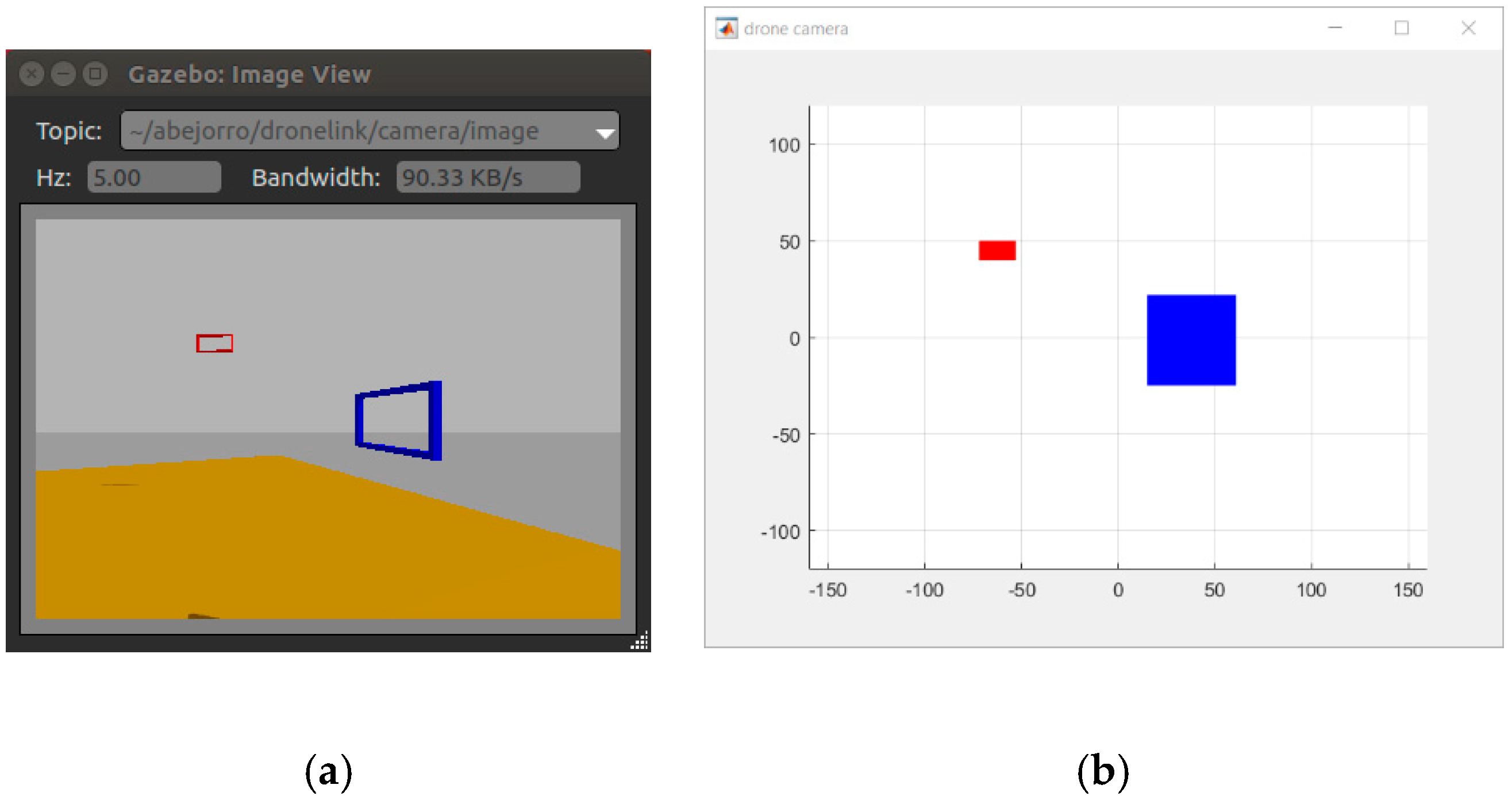
23], which is a drone programming competition focused on promoting skills related to computer programming and mobile robotics among secondary school students in the Spanish region of Castilla-La Mancha. The specific challenge consists in programming a quadcopter (one of the most popular drone types) so that it can take off from a base, go through several colored floating frames (see
Figure 1) in a specific order, and finally land at the starting point. The navigation system proposed by each student team is evaluated in different scenarios, in which the position and orientation of the frames and the drone itself are unknown a priori.
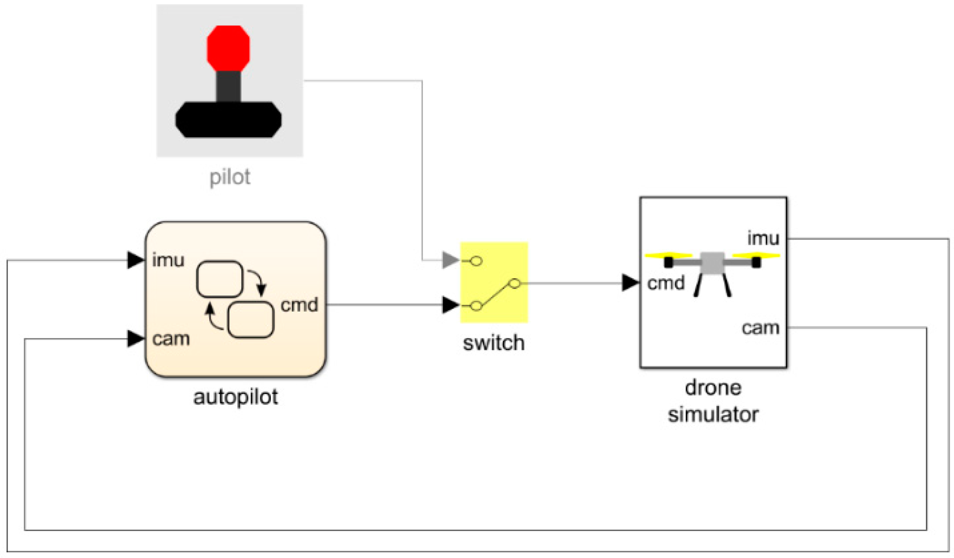
As is shown in
Figure 2, the autonomous drone navigation system is built on top of three subsystems integrated into the framework. The location subsystem provides the position and orientation of the drone in the scenario, for which it uses an ideal IMU. The vision subsystem provides the relative position of the frames with respect to the drone itself. This information is extracted from the images obtained by a fixed built-in camera located on the front of the drone. Finally, the low-level control subsystem acts on the rotors to keep the drone stabilized in the air, or to execute basic maneuvers.
The rest of this paper is structured as follows.
Section 2 presents a general description of the complete development and test framework, focusing on the interaction between the navigation system and the location, vision, and control subsystems. The internal implementation of these subsystems can be found in [
24]. Then, and for illustrative purposes,
Section 3 describes the development of a simple navigation system proposal according to the rules of the above-mentioned student competition, and
Section 4 studies its behavior in various test scenarios. After that, and as a possible practical application of the proposed simulation framework,
Section 5 briefly presents the “ESII Drone Challenge” contest. The interested reader can find more details about different editions of this competition in [
24]. Finally,
Section 6 contains our conclusions and lines for future work.
3. Implementing Autonomous Navigation Systems
After describing our development framework, as an example of its use this section details the implementation of a relatively simple autonomous navigation system proposal meeting the goals of the challenge mentioned in the Introduction section.
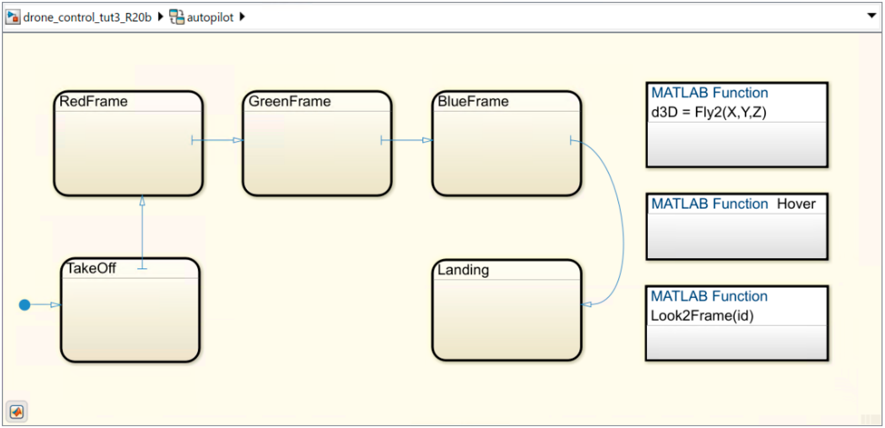
Figure 7 shows the contents of the autopilot Stateflow block presented in
Figure 3. This state machine is run every
, so the navigation system runs at
. Considering that the low-level stability control runs directly on Gazebo (at
), the navigation system execution rate proves to be more than sufficient for our purposes.
Internally, the state machine contains five superstates (so called because they in turn contain more states). The navigation system starts in the TakeOff superstate, which is responsible for starting the drone engines and raising it into the air. Later, the system switches to the RedFrame state, in which the drone locates the red frame in the scenario, navigates to it, and passes through it. The GreenFrame and BlueFrame states define similar behaviors. After going through all the frames, the system shifts to the Landing state, which is responsible for returning the drone to the base and landing it. The diagram in this figure is completed with three global MATLAB functions that implement basic primitives used in different states. The Hover function keeps the quadcopter suspended in the air. The Fly2 function implements the navigation to a 3D position. Finally, the Look2Frame function makes the drone “stare” at a specific frame. All these components are detailed below.
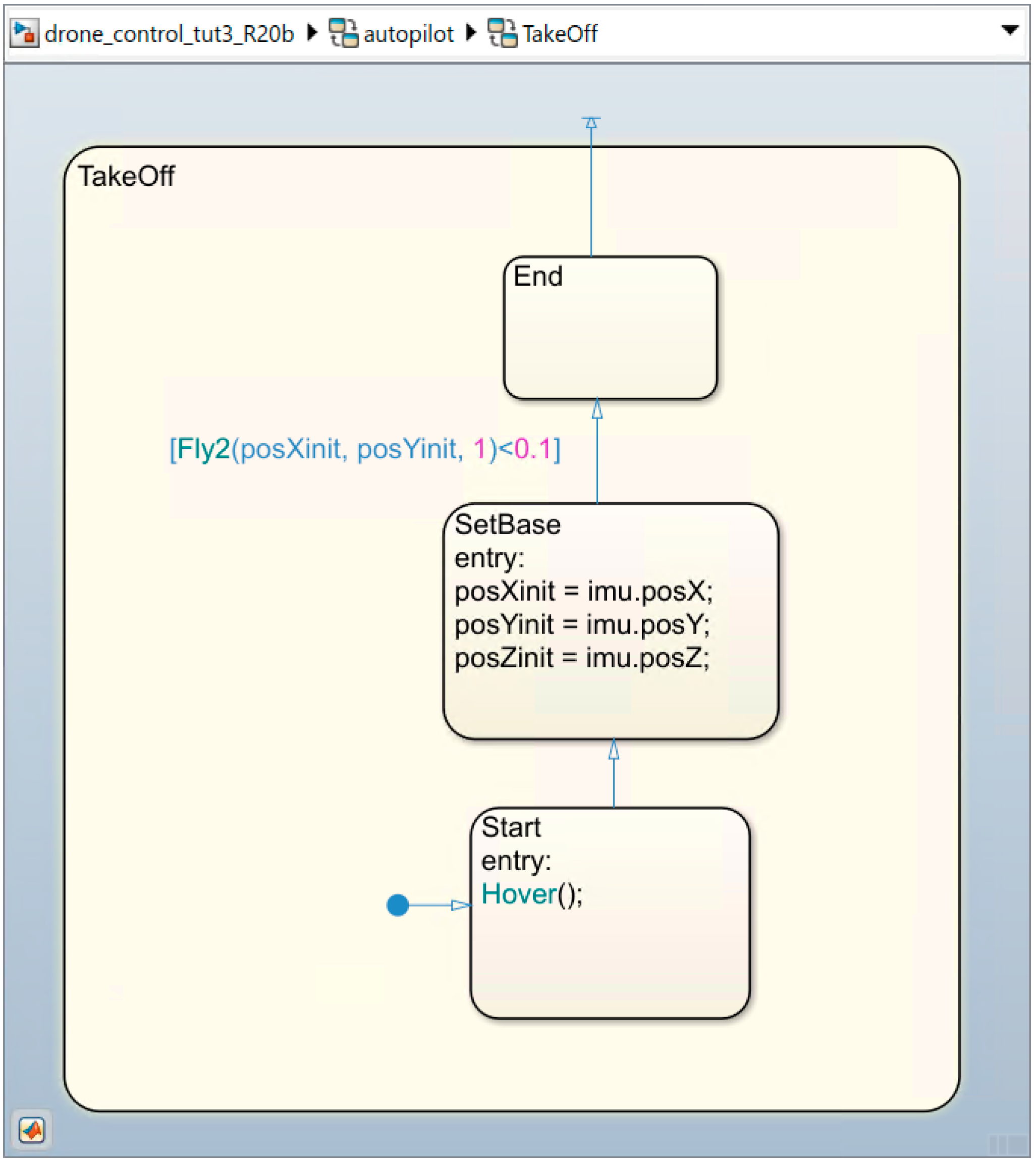
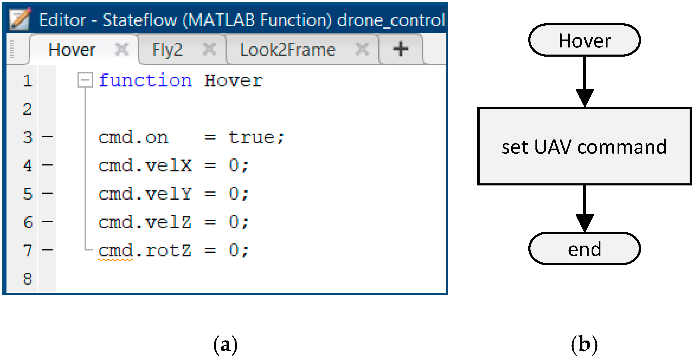
Figure 8 shows the TakeOff superstate. First, the Start state executes the Hover function. As indicated, this simple function, which is detailed in
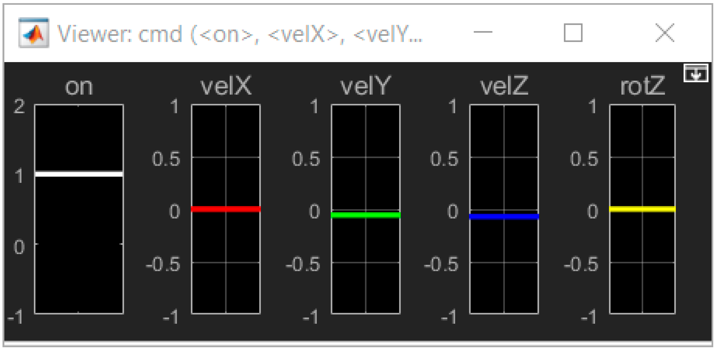
Figure 9, causes the drone to remain suspended in the air, in its current position. To do this, it indicates through the
output bus the corresponding commands to turn on the motors (if they were previously turned on this action has no effect), and restart the reference velocities
described in
Section 2.3.
After the activation of the motors, the state machine switches directly to the SetBase state. The purpose of this state is to assign the initial drone position since this will also be its return position after completing its mission. As shown in
Figure 3, the autopilot Stateflow block receives the current drone position through the imu input bus, which has no valid information until the second execution of the state machine. Therefore, this assignment cannot be made in the Start state, which explains the existence of this second state.
From the SetBase state the machine will pass to the End state when the condition defined in the transition is satisfied, which will require an undefined number of executions of the state machine. That condition invokes the Fly2 function, which receives the 3D position to which we want the drone to move and returns the distance remaining to reach this position. Consequently, the navigation system requests that the drone rise from its position over the takeoff and landing base to a height of exactly . Since the base is a cube of edges, the drone will rise above it. When there are less than left to reach the desired height, the condition is satisfied, and the system changes from the TakeOff superstate to the RedFrame superstate.
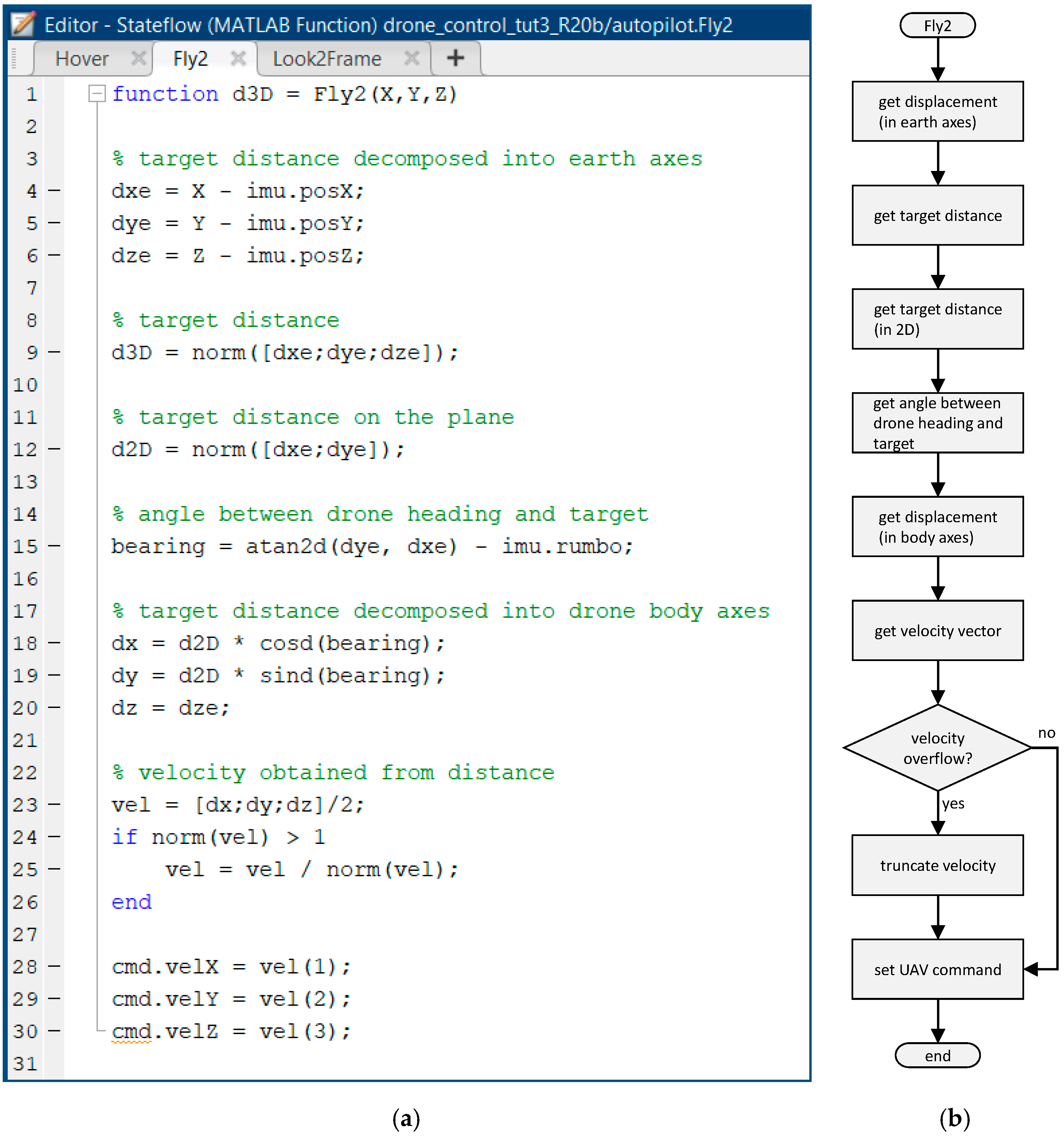
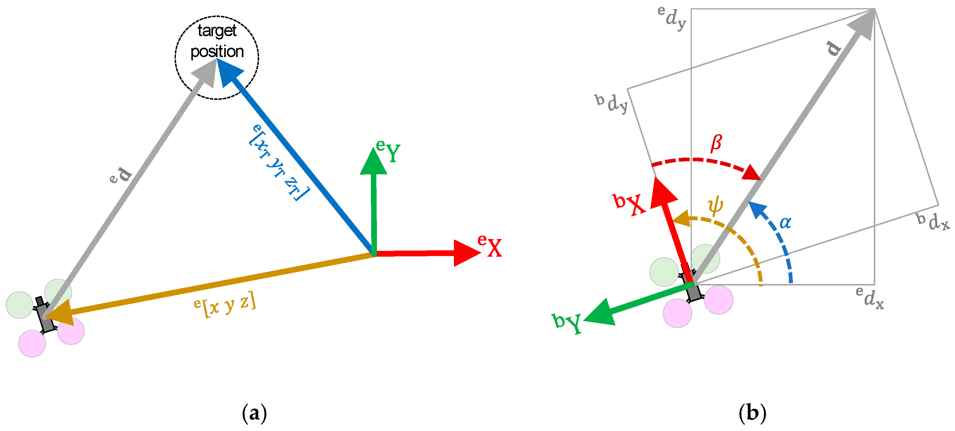
Figure 10 shows the implementation of the Fly2 function.
First, the displacement vector
, from the current position
(provided by the IMU) to a target position
, is computed by means of the expression
(see lines 4–6 in
Figure 10 and
Figure 11a). From this vector, we obtain the three-dimensional distance to the target
(line 9), which will be returned by the function and managed by the navigation system. The displacement vector
obtained is expressed in the earth coordinate system, but horizontal movements require it to be expressed in the quadcopter reference system. For this purpose, the distance to the target on the plane
is obtained (line 12). Next, we compute the angle between the displacement vector
and the
axis by applying the expression
. Starting from that angle and the course followed by the drone (provided by the IMU), we can compute the bearing angle
(line 15 and
Figure 11b). Finally, the above values are used to transform the horizontal displacement vector
(lines 18–20). Note that the transformation of the horizontal and vertical distances is performed separately, ignoring the fact that the drone is not always fully stabilized. Then, the commanded velocity vector is obtained directly from the distance vector (line 23), to which a correction factor of value
is applied to smooth the maneuver. In addition, the system limits the commanded velocity to the range
. Therefore, the velocity vector is truncated to that upper bound (lines 24–26). Finally, the velocity vector is dumped to the corresponding output bus (lines 28–30).
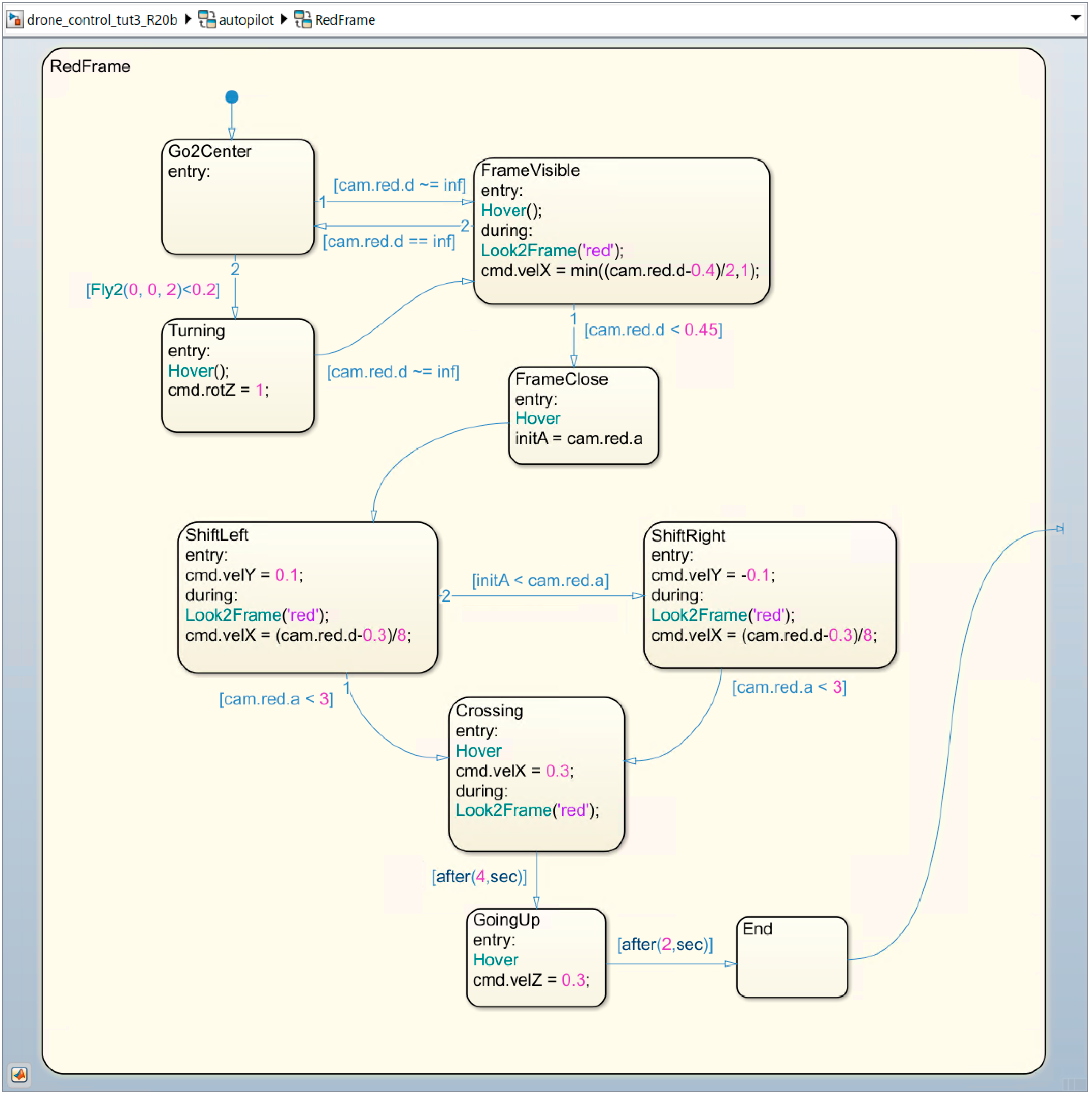
Figure 12 shows the behavior implemented in the RedFrame superstate, which can be summarized as follows. Once the drone is located at the desired height over the base, the navigation system switches to the Go2Center state. While in this state, the drone navigates directly to the center of the scenario at a height of
, as indicated by the priority transition 2. When there are
left to reach the center of the scenario, the system passes to the Turning state. The drone stops and starts rotating. The implemented behavior assumes that, at some point during the trip to the center or the subsequent rotation, the drone will detect through its camera the desired frame (in this case the red one), and will change to the FrameVisible state. This occurs when the cam input bus provides a finite distance for that frame. Note that in the Go2Center state, the frame detection check is given higher priority than the center-reach check. Therefore, if during the trip the frame is discovered, the drone will pay attention to it and stop moving towards the center.
Upon entering the FrameVisible state, the drone interrupts its current movement, consisting in going to the center of the scenario or rotating, as explained above. It then begins its approach to the frame, which is broken down into two parts.
Firstly, the Look2Frame function makes the drone keep a colored frame in the center of the image captured by its camera.
Figure 13 shows its implementation. The colored frame in question is passed as an argument (line 1), and the corresponding bus information is selected (lines 3–10). If the frame is displayed on the screen (line 12), the horizontal center of its visible area is calculated (line 13) and a certain Z-rotation speed is applied to match that center with the center of the image (line 14). In the same way, the vertical center of the visible area of the frame is calculated (line 15) and a certain displacement velocity in Z is applied to make the drone ascend/descend to the same height (line 16).
While keeping the camera focused on the frame, the drone tries to approach to within of it by applying a certain forward velocity on the front X-axis. If for any reason the drone should lose sight of the frame, then the navigation system returns to the Go2Center state to try again. The drone acts in this way until it successfully approaches to within of the frame. After that, the state machine transitions to the FrameClose state.
In the FrameClose state, the drone stops its forward movement to begin turning around the frame and get into position to pass through. The camera processing system is quite rudimentary, and it reports the tilt angle as an absolute value (no sign). Therefore, the drone does not know, a priori, to which side it should turn. The strategy we adopt is the following: the drone turns to any side and then checks whether it was right (and continues), or wrong (and rectifies). The system records the current angle and changes to the ShiftLeft state.
The ShiftLeft state applies a slight side shift velocity (to the left). At the same time, it generates corrections so that the drone keeps the frame focused and comes a little closer to it (at a distance of ), as explained for the FrameVisible state. If the shift to the left makes the tilt angle increase, it is because the drone should have turned in the opposite direction, consequently transitioning to the ShiftRight state. This state is like the previous one, except that the sideways shift velocity is applied to the right. For both side shift states it is assumed that, when the angle is less than , the drone is sufficiently aligned with the frame to be able to pass through it, transitioning to the Crossing state.
In the Crossing state, the quadcopter is correctly oriented in front of the frame, at . All lateral movements are stopped, and a moderate forward velocity is applied. Given the distance to be covered and the speed applied, after the quadcopter should have passed through the frame. Note that, if possible, the drone continues to make corrections to keep the frame centered on the camera image. Finally, the frame disappears from the camera’s field of view, and the drone advances “blindly” for the last stretch. After crossing, the drone rises for to move away from the plane of collision with the frame. The superstate then changes to the End state, and the navigation system moves to the Landing superstate.
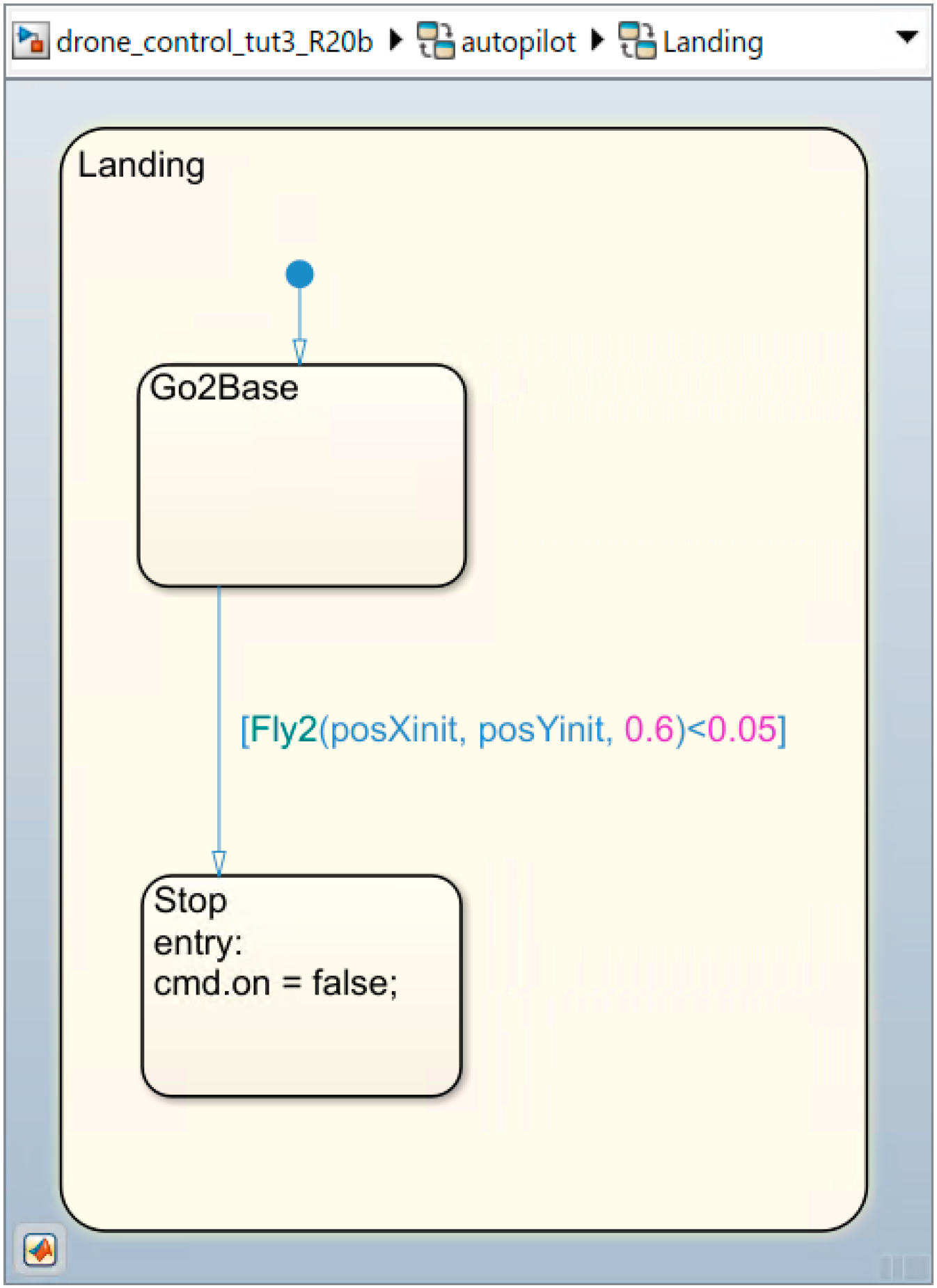
The implementation of the Landing superstate is shown in
Figure 14.
When the drone is less than from its destination, the navigation system stops the engines so that the drone falls onto the base. This option has been chosen, instead of a soft landing, since in the said competition the time between the activation and deactivation of the engines is evaluated, thus gaining a few valuable seconds.
5. Practical Application
“ESII Drone Challenge” is a contest for high school students. Each team must improve the simple navigation system described in
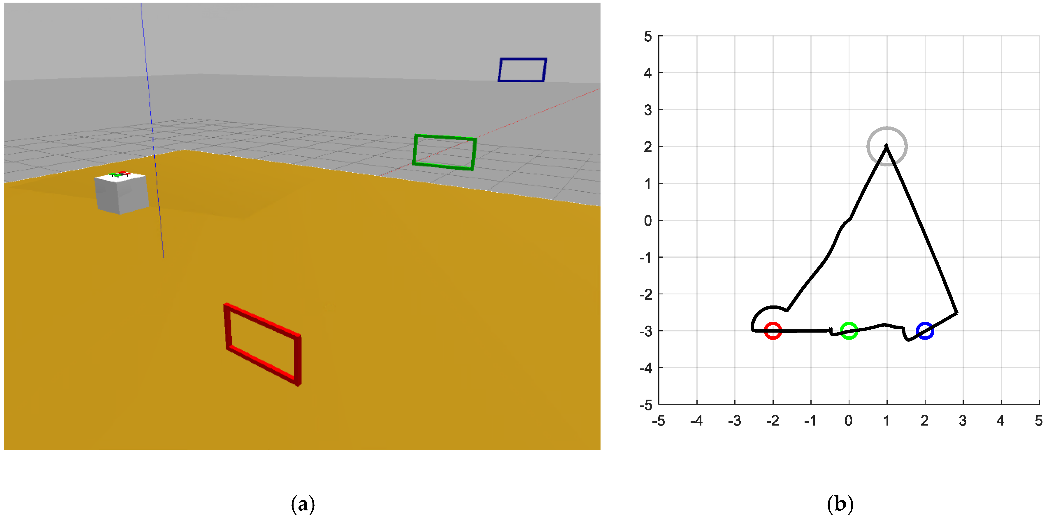
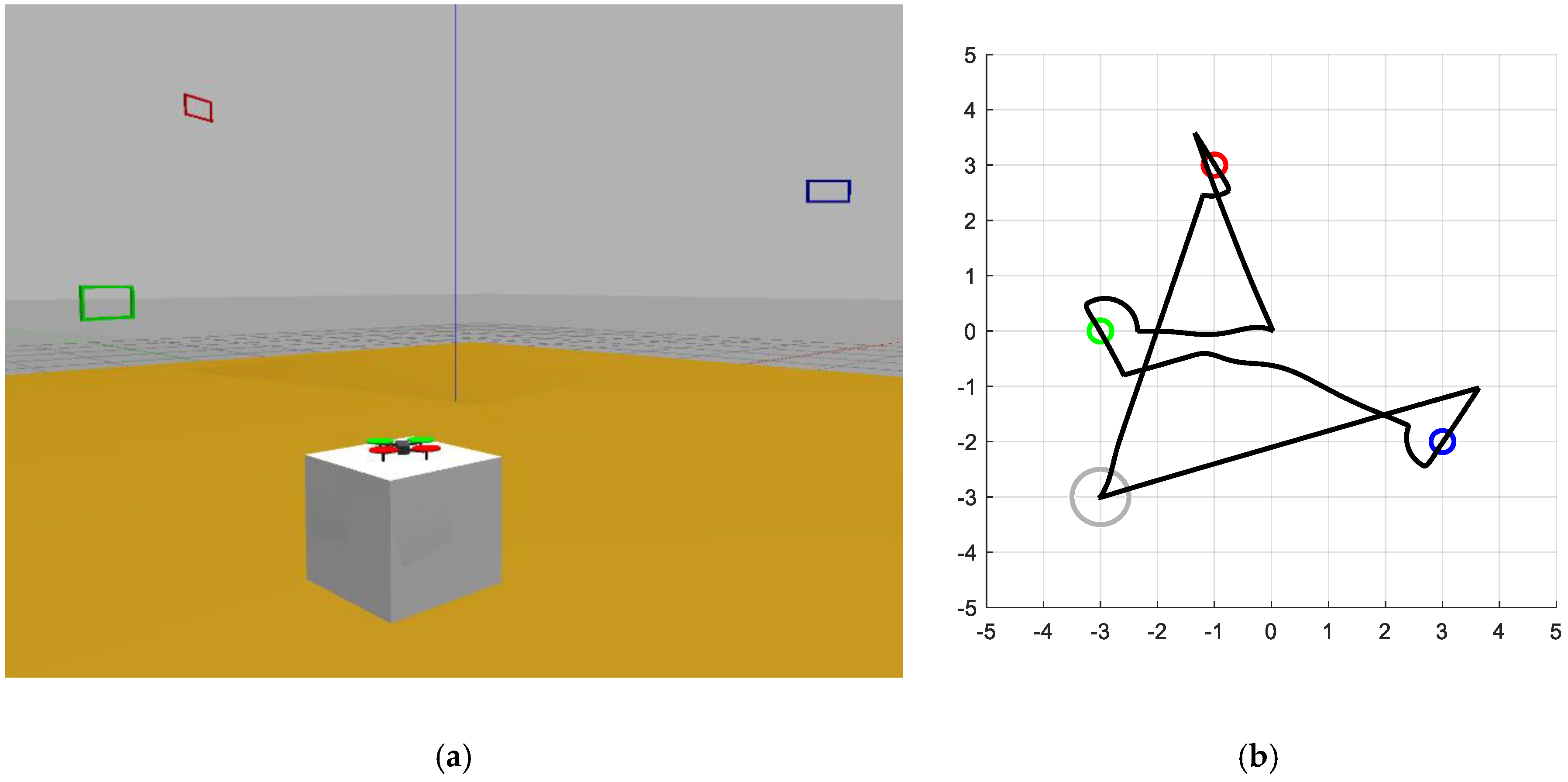
Section 3. Participants are encouraged to choose their own strategy, stimulating their creativity. To evaluate the quality of the proposals, they are tested in different scenarios, similarly to what has been done in
Section 4 for the baseline system.
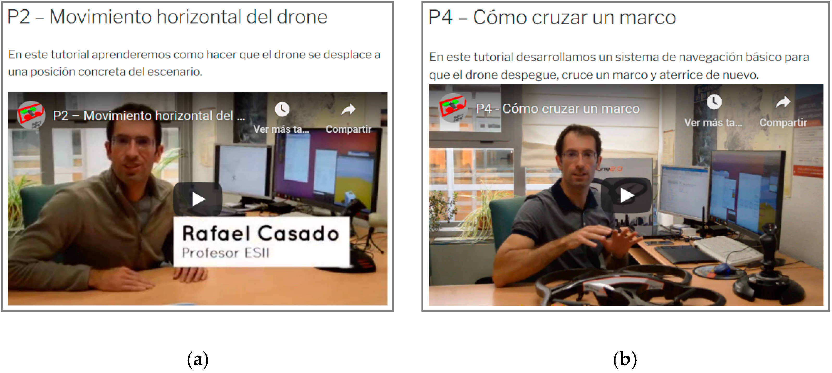
The contest has an initial phase, which lasts several weeks, in which the enrolled teams must develop their proposals in their respective schools. Students can access to the contest “official” blog, which contains a set of video tutorials organized in several categories (
Figure 18). Through these tutorials, the organization provides detailed instructions for installing and configuring the working environment and gives advice and suggestions for the development of the proposals. Video tutorials are complemented by a traditional “FAQ” section.
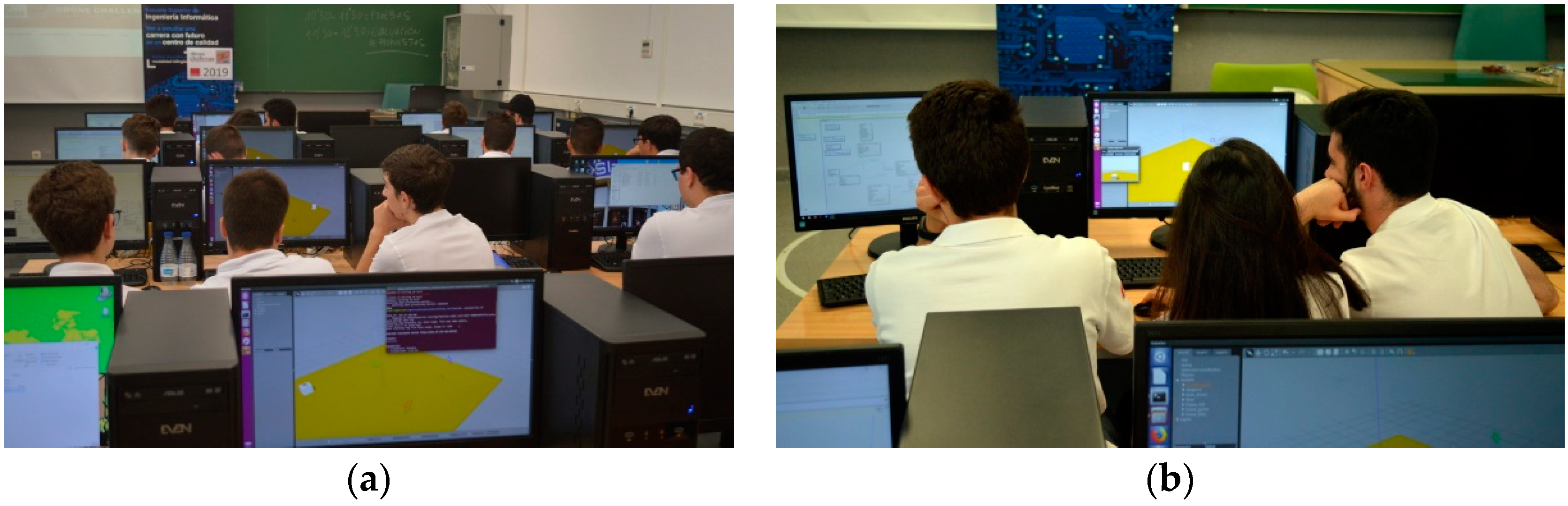
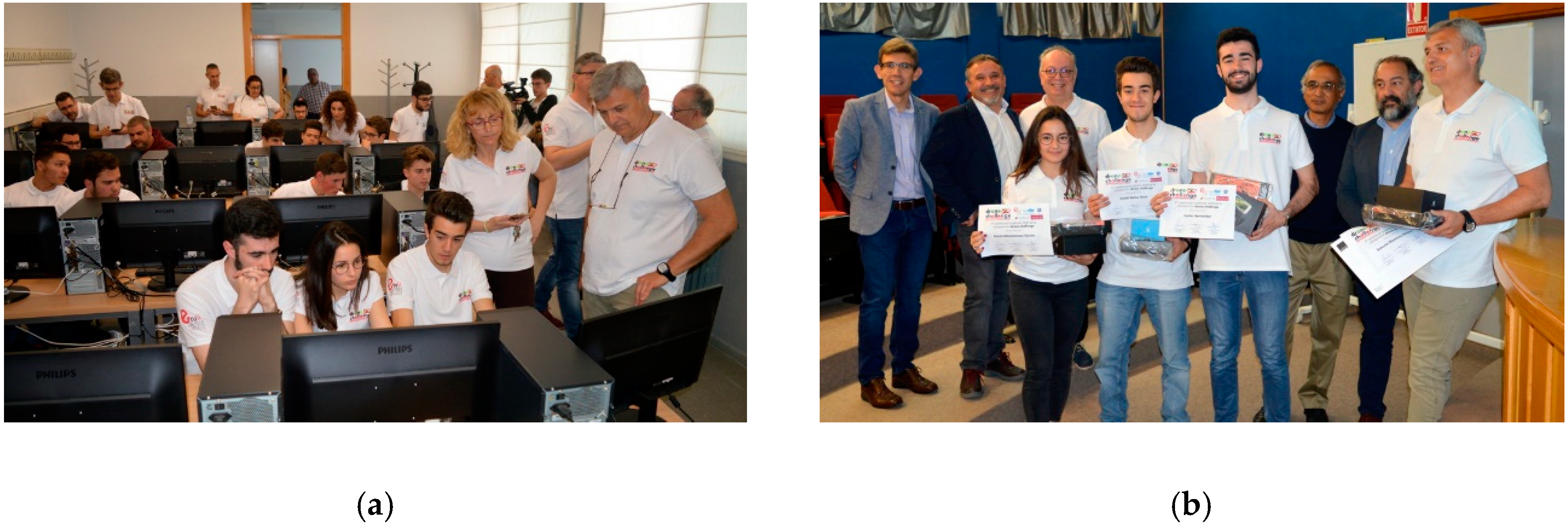
The final phase takes place in the facilities of the School of Computer Science and Engineering. During the first part of this phase, teams test their navigation systems in several different scenarios, and they can made last-time tunings to their implementations (
Figure 19).
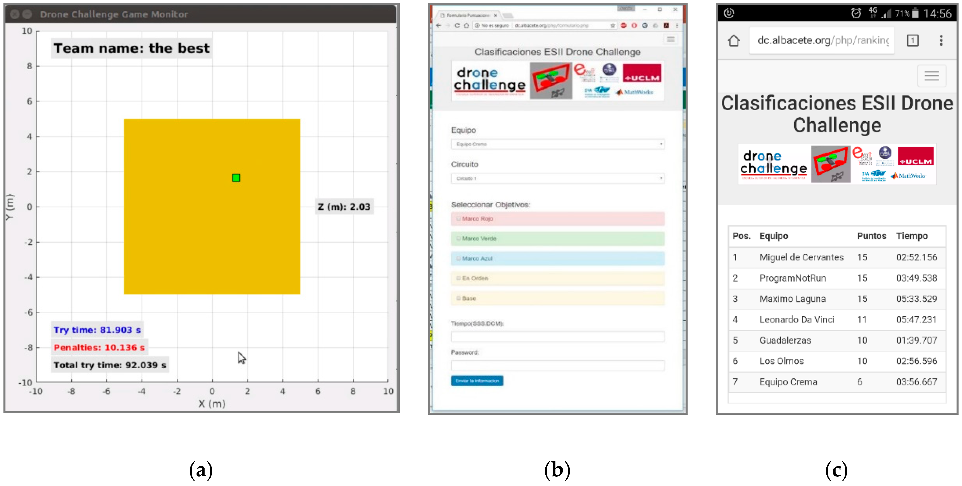
Later, all the proposals are frozen, and three of the previous scenarios are randomly chosen. Student proposals are then tested in the selected scenarios, under the supervision of the competition judges. A supporting application, the “Game Monitor” (
Figure 20a), allows the judges to measure the time required to complete each try. It is a separated Simulink application that connects to the drone simulator (in Gazebo) to provide the time the drone engines are on. This tool is also in charge of checking whether the drone exits the flying scenario (a
cube), since this situation must be penalized, and whether the try has reached the available time (set to
).
Apart from the “Game Monitor”, a small client-server application (
Figure 20b) was developed for the final phase so that, while the competition judges are assessing proposals (
Figure 21a), participants can check their “virtual” place in an instantaneous ranking (
Figure 20c). To have this ranking updated in real time, each judge uses a smartphone to fill in a web form with the results of each try and sends this information immediately to the server.
Finally, although student proposals are developed and tested by simulation, the prize is a commercial drone for each one of the components of the winner team (
Figure 21b). It is worth mentioning that the results of the survey conducted after the second edition of the competition [
24] indicate that participant students had a very positive opinion about the simulation framework.
6. Conclusions and Future Work
In this work, we have described a simulation framework for the development and testing of autonomous drone navigation systems. We consider that this tool can greatly facilitate the acquisition of competences and skills for engineering students who are starting out in the field of aerial robotics. This is because, unlike similar tools, the framework does not require an in-depth knowledge of robotics or programming, and drone behavior is mainly defined in a graphical way, by means of very intuitive state machines. Additionally, low-level control details have been abstracted, so that the programmer is only required to be familiar with a simple interface for receiving drone states and camera information and for sending navigation commands.
We have also shown, through a simple example, how we can use this framework to develop a navigation system proposal. In particular, the example presented is inspired by the “ESII Drone Challenge” student competition. A possible (and non-optimized) implementation for a navigation system meeting the objectives of this competition has been detailed. Additionally, we have outlined how this simple proposal could be evaluated in different test scenarios.
Future work can be undertaken along many different lines. One such line is related to enhancing the proposed navigation system. Firstly, it is necessary to improve the scenario exploration process, as inspecting the environment from its center is a very limited behavior that presents problematic situations. For example, the desired frame may be in the center, but at a different height. Instead, the drone could memorize the regions it has inspected and those that are still pending. Furthermore, the drone is currently only aware of the relative position of its target (either the center of the scenario or a colored frame). It would be useful to consider the possible need to avoid an obstacle (another frame) in the attempt to reach its destination. In general, it would be more appropriate to perform a collective analysis of the frames, and even to memorize the position of non-target frames, with the purpose of speeding up their localization when they have to be passed through later.
Secondly, improvements could be made to the quadcopter model. The image processing system could study the perspective of the captured frames, thus improving the accuracy of their estimated position and orientation to avoid unnecessary lateral displacements. A more thorough analysis of the image could also be carried out to identify and locate various types of targets to be reached or hazards to be avoided. In addition, apart from the basic IMU, the drone could incorporate a LiDAR sensor [
26], which would help to estimate the position of the obstacles around it. This type of systems is supported natively in Gazebo, so its incorporation would be relatively simple. All this would allow us to consider more complex and realistic scenarios for the development of autonomous navigation systems with greater applicability.
Finally, it is desirable to complement the simulator with real drones moving through real scenarios, validating the developed navigation system. The model-based design methodology supported in MATLAB/Simulink simplifies this process, culminating in the development of the final product. In this way, the proposed framework would acquire a much more attractive dimension that would encourage the research spirit in the students and promote technical curricula in the development of autonomous navigation systems.


