Abstract
This paper presents the results of recent work to develop and trial a mine machine radar sensor for underground coal mine vehicles. There is an urgent industry need for an integrated solution to the problem of operating an underground vehicle in conditions of dense ambient dust and/or smoke, such as may occur in underground coal mines after a fire or explosion. Under these conditions, sensors such as cameras and lidar offer limited assistance due to their inability to penetrate thick dust. Thermal infrared can penetrate dust but still results in poor vision, as there is insufficient temperature contrast between the tunnel walls and the ambient air. Microwave radar sensors are able to penetrate the dust, and suitable radar sensors have been developed for use in the automation industry. Adapting such sensors for use in an underground coal mining environment was the focus of this research effort, and involved trialing a suitable sensor in dust and smoke chambers as well as trials in an underground coal mine with introduced dust. Data processing and the development of a suitable user interface were key aspects of the research. Since any sensor would have to operate in an explosive atmosphere, a related research work developed a flameproof dielectric enclosure to allow the use of the radar in the mine environment.
1. Introduction
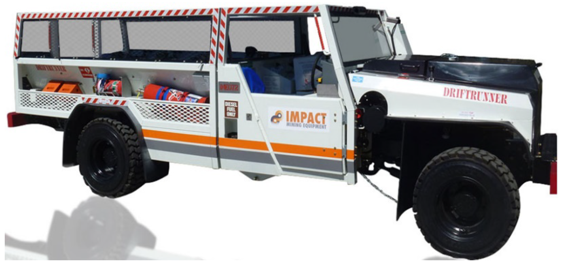
As technology improvements accelerate the trend towards the implementation of the digital mine—delivering mine-to-plan productivity with high levels of control for resource extraction—the impact of exceptions, and the importance of exception-handling, becomes more critical. An extreme example of an exception incident in an underground coal mine environment is a fire or explosion. Explosions and fires in underground coal mines are extremely dangerous, typically resulting in catastrophic outcomes. Even if miners are not killed in the initial incident, they face a tremendous challenge to escape safely. Due to the likelihood of additional explosions and/or structural collapse, additional personnel are generally not permitted to enter the mine to attempt a rescue; rather the emphasis in the industry is on “self-rescue”. To this end, compressed air breathing apparatus (CABA) kits and other equipment are stored at regular intervals throughout underground coal mines to provide operators with the vital oxygen required to survive when the mine ventilation system is not functioning. Walking out of a large underground complex, however, can be an extremely arduous task under such conditions, and is often impossible for injured personnel. Mine personnel carriers similar to the Driftrunner™ (Figure 1) have been used by miners in the past to escape from a mine after an explosion, for example during the Moura No 2 mine disaster of 1994, but the Warden’s Inquiry Report for that incident noted that the miners’ “passage out of the mine was impeded by poor visibility” [1]. After a significant explosion, the mine environment is typically filled with dust and/or smoke, and under such conditions it may not be possible to successfully guide the vehicle or navigate egress from the mine.

Figure 1.
“Driftrunner” underground coal mine vehicle.
In the wake of the Moura No 2 disaster, recommendations were made for the development of either rescue or escape vehicles to enable “motorised transport in emergency escape” situations [2]. A further trigger was a mine safety exercise held at Kestrel Mine [3], which provided evidence of the practical dilemma faced by survivors who could be several kilometres in-bye (distance from the surface), so that rescue or escape on foot was not possible. Based on this evidence, it was agreed that a guidance system should be developed that could be retrofitted onto a personnel transporter. The Australian Coal Association Research Program (ACARP), therefore, sponsored a Mines Rescue Vehicle Research Project (MRVRP) to develop such a guidance system. Due to the poor visibility typically prevalent after an explosion underground, the MRVRP recognised the need for sensing technologies that could function effectively despite ambient dust and smoke, and aid the driver’s ability to locate their relative position, direction of travel and avoid impacting obstacles and/or the mine walls [4]. It was further recognised that if a suitable sensing technology could be identified and adapted for use in an underground coal mine, it could provide not only a means for escape during an emergency scenario, but also a reliable source of data for mapping and monitoring the mine environment that would contribute to the ongoing development of digital mine capability. Sensing technologies considered for this role included:
- Lidar (laser scanners)
- Thermal Infrared (IR) Cameras
- Ultrasonic range finders
- 1D and 2D radar sensors
While commercial ultrasonic range finders showed good performance in dusty atmospheres, and were trialled successfully in an underground mine as part of the MRVRP [4], they are inherently unsuited to regular operation an underground coal mine as they cannot function inside a flameproof enclosure—a necessary feature for the operation of off-the shelf electrical equipment in potentially flammable atmospheres—nor can they be easily modified to achieve the IECEx certification (International Electrotechnical Commission System for Certification to Standards Relating to Equipment for Use in Explosive Atmospheres [5]), which is required for an electrical device to be used without added protection, such as a flameproof enclosure. For this reason, only lidars, thermal IR and radar sensors, which can all operate in a flameproof enclosure, were trialled in the current research project. Further comprehensive testing was previously carried out to evaluate the performance of SICK lidar technology under various dense ‘black’ and ‘white’ smoke and coal dust conditions [6].
2. Materials and Methods
The research project proceeded through several stages, including initial sensor testing, user interface design, lab testing in a dust chamber and, finally, field testing in an underground coal mine.
2.1. Sensor Selection
For each of the various sensing options considered, there were a range of available commercial options. There were also two separate use cases considered as part of the project: first, a primary forward-facing sensor with the ability to provide angular discrimination, i.e., a scanning sensor; second, one or more auxiliary sensors that would be side-facing to provide range to the walls of the mine roadway, for basic navigation and collision avoidance. A set of minimum performance criteria (MPC) was established for the primary forward-facing sensor, as shown in Table 1. The criteria for minimum range requirements (and corresponding sensor update rates) were determined based on direct feedback and published articles from mine-site personnel involved with developing a response to the Moura No 2 mine disaster [2], complemented by published research into human reaction times for collision avoidance [7]. A minimum effective range of at least 20 m was specified by the ACARP industry project monitors as sufficient for vehicle navigation in an emergency due to the low speeds expected to be employed by operators under these circumstances.

Table 1.
Sensor System Performance Criteria.
Based on these criteria a lidar, a radar and two infrared cameras were selected for the trial. All the sensors selected could meet the MPC for non-dusty conditions, and all were considered possible candidates for use in dusty or smoky environments.
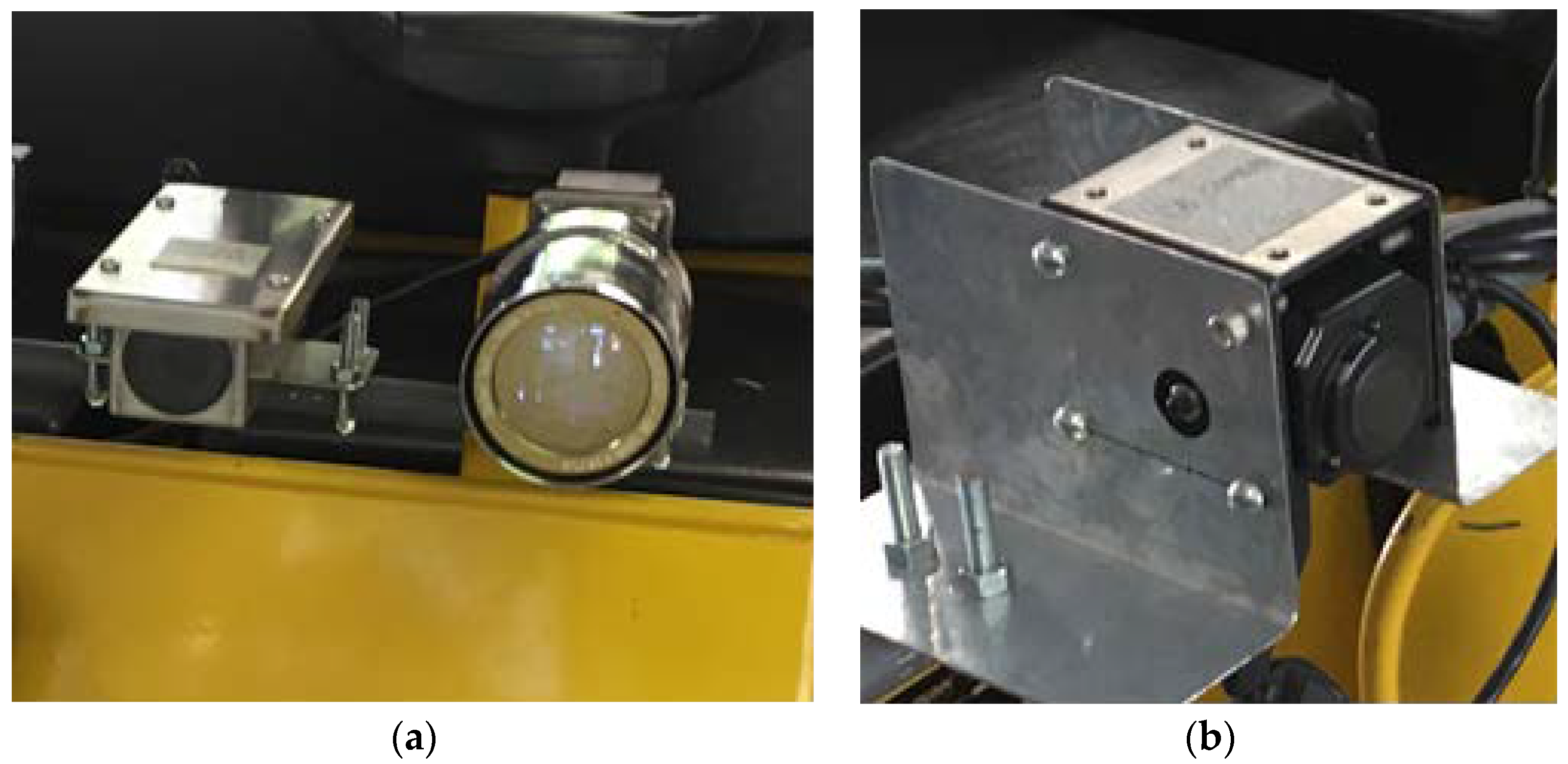
The IR cameras trialled were a short-wave infrared (SWIR) camera (wavelength 900–1700 nm) and a thermal long-wave infrared (LWIR) unit (wavelength 8–15 µm) (Figure 2) [8]. These units, if operable in the target conditions, were intended to provide the primary visual feedback mechanism for the driver, since direct vision provided by video is the closest analogue to operating under normal driving conditions. In addition, a standard (non-thermal) video camera was trialled to provide a basis for comparison with the IR systems (Figure 2a).
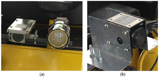
Figure 2.
(a) standard vision camera (left) and SWIR camera (right); (b) thermal LWIR camera.
Two lidar systems were trialled, including one that featured a multi-echo sensor [9], meaning that it had the capability to reject some of the spurious echoes associated with airborne smoke or dust particles, and thus improve the likelihood of providing reliable ranging to target. Both lidar systems utilised a near-infrared laser (wavelength 905 nm) in a time-of-flight configuration to provide range-to-target information; they also feature an internal spinning mirror that provides a two-dimensional (2D) scanning functionality. The smaller lidar was also mounted on a rotating platform to provide a third axis of rotation, thus enabling a three dimensional (3D) point cloud to be produced when the data is processed. The complete lidar system was installed in an IECEx Exd (flameproof) enclosure designed by CSIRO to allow the system to operate in an underground coal mine (Figure 3).
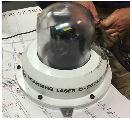
Figure 3.
Lidar system in flameproof enclosure.
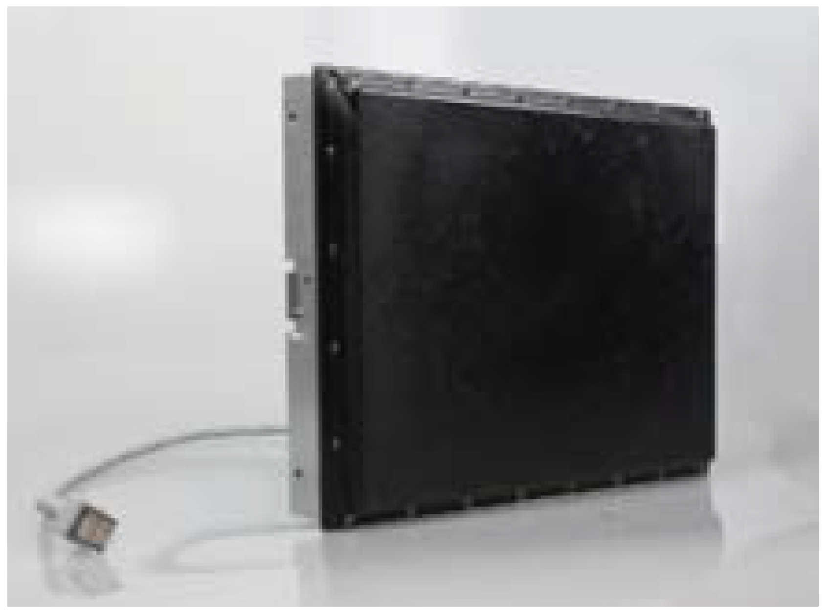
The third sensor employed for the initial trials was a 2D automotive radar: a K-band microwave device operating at 24 GHz (Figure 4). The radar was a phased-array sensor that performs azimuth discrimination by means of electronic scanning, so there were no mechanically moving parts in the sensor. The sensor was trialled with a dielectric cover, as it would need to be able operate inside a certified flameproof for eventual underground deployment.
Figure 4.
Automotive radar sensor.
Of the three primary sensing modalities that were employed, the radar was considered to be the most prospective candidate for effective operation in dusty conditions [10]. This was due to the fact that, as a microwave sensor, the operative wavelength of the radar is far longer (12–13 mm) than the other candidate technologies. The radar sensor specifications are shown in Table 2.
Table 2.
Radar Sensor Specifications [11].
These specifications exceed the minimum performance criteria as specified in Table 1.
2.2. Laboratory Testing
Before deploying any of the candidate technologies in an underground environment, a series of tests was performed to determine the efficacy of the different sensors in the presence of ambient smoke and dust. These trials were carried out at the Simtars Redbank facility in Brisbane, Australia. The smoke tests were performed using standard non-toxic smoke bombs in a semi-enclosed space to allow for rapid ventilation after testing. The dust testing was carried out in a controlled dust chamber fitted with inlet and exhaust fans.
The goal of the testing was to establish, for each candidate sensor, the compliance with the minimum performance criteria (MPC) as described in Figure 5. All the selected sensors were specified to achieve the required MPC for range accuracy, angular discrimination and update rate (for the camera systems, range accuracy is not applicable, but angular discrimination can be equated to resolution, and the update rate is equivalent to the camera frame rate). Thus, the only criterion to be confirmed by the testing was the sensor performance under conditions of ambient dust or smoke.
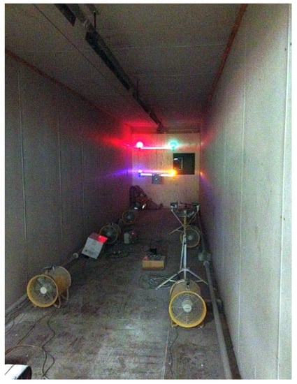
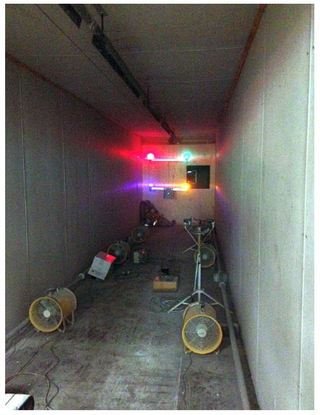
Figure 5.
Dust chamber with test lighting mounted on moveable target frame.
Initial testing for the lidar and radar, including both smoke and dust trials, was carried out in the dust chamber to allow for rapid evacuation of the dust and/or smoke. The range testing was limited by the length of the chamber (approximately 10 m); however, the test was intended to serve as a mechanism for eliminating candidate sensors that could not achieve a full-range measurement, even under these restricted circumstances. Because of the presence of dust and smoke, it was not practical to manually move the sensors on a trolley for range testing to a fixed target. Instead, an overhead rail was installed to allow a target frame to be moved from one end of the chamber to the other during testing (Figure 5). The lights shown on the mounting frame were used to demonstrate the relative visibility of different coloured lights in smoke or dust: due to the longer wavelength of red light, this beacon was most persistent as visibility decreased.
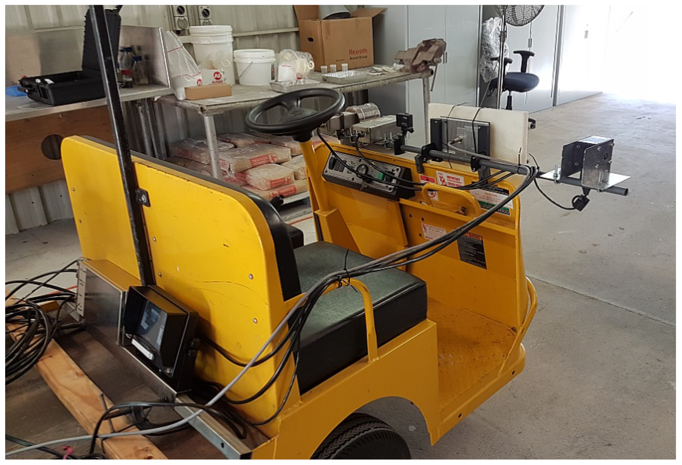
The results for these initial dust chamber trials are described in Section 3. Based on these outcomes, further testing was restricted to the radar and IR camera technologies. After a series of tests, a demonstration of the results was carried out in the presence of mining industry representatives in order to gain approval for an underground coal mine trial. These extended tests and demonstrations included the development of a mounting rail that could be deployed on a mine transporter, allowing the sensors to be tested on a motorised trolley vehicle (Figure 6).

Figure 6.
Cameras and radar mounted on motorised trolley for mobile testing.
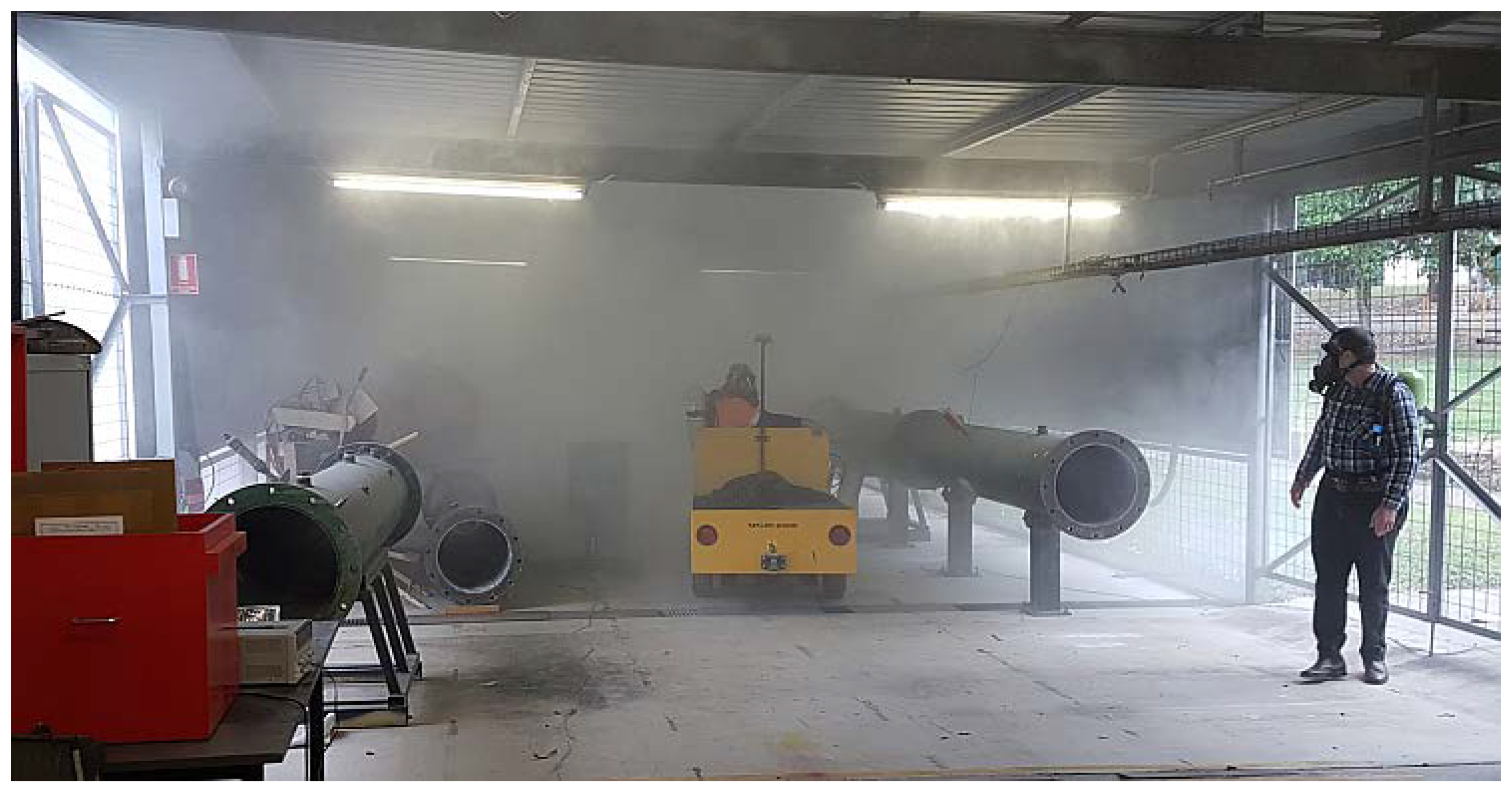
The radar sensor is mounted centrally on the rail, and its forward face is covered by a block of polycarbonate equivalent to the dielectric material that was planned to be used for the radar flameproof enclosure. The vehicle was driven by an experience operator who wore the compressed air breathing apparatus (CABA) that is used in coal mines for self-rescue situations when a fire/explosion has occurred, or when the ventilation system has failed (Figure 7).
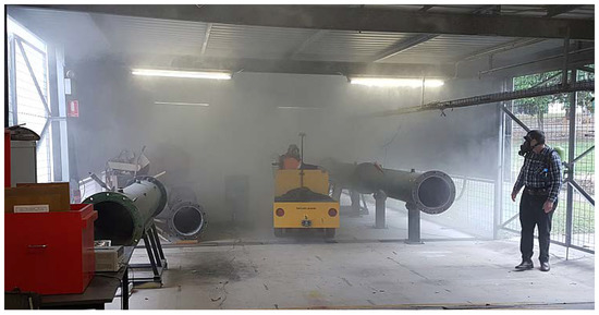
Figure 7.
Operator wearing CABA driving the test trolley through smoke.
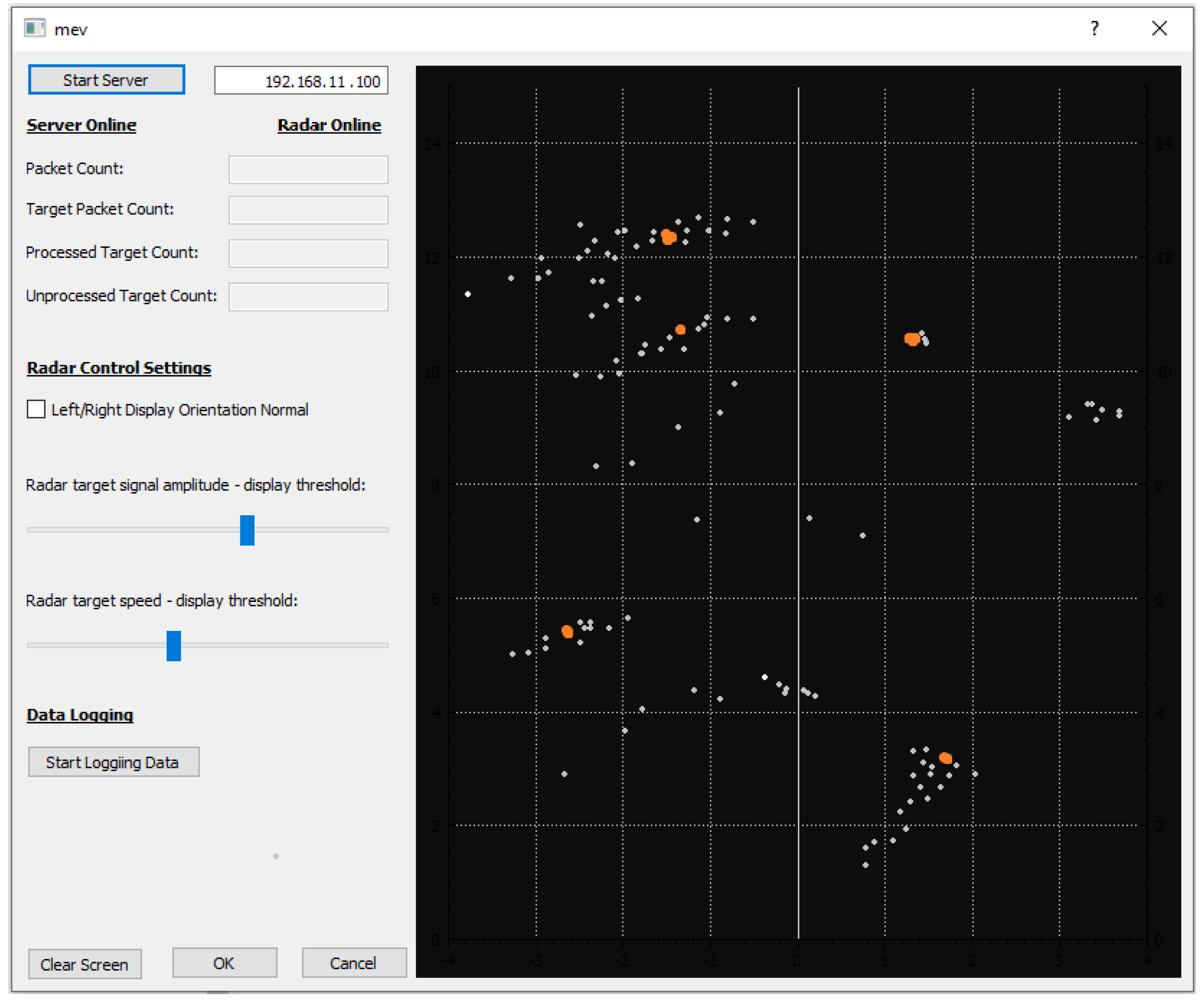
The radar data were displayed in real-time on a laptop user interface using software custom-developed by the CSIRO. The interface included basic features such as range and intensity of target returns and target persistence to aid navigation (Figure 8, the orange markers indicate live targets while smaller, the grey markers indicate historical target echoes that are retained for a preset time window). The initial in-house and field trials used this basic user interface, but in parallel, work continued on the development of advanced processing algorithms to render the complex radar data more amenable to a human operator, and thus more easily integrated into a mine-wide digital management architecture.
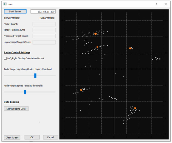
Figure 8.
Prototype user interface for initial radar sensor trials.
The results of the extended laboratory testing are summarised in Table 3. In Section 3. Based on these results, it was resolved that a trial of the radar technology (in conjunction with a thermal IR camera) should proceed in a negligible explosion risk zone (NERZ) of an underground coal mine. In conjunction with the industry partners for this research project, a trial was arranged at a suitable mine in the Newcastle region of New South Wales, Australia.
Table 3.
Summary of Sensor System Performance in Laboratory Testing.
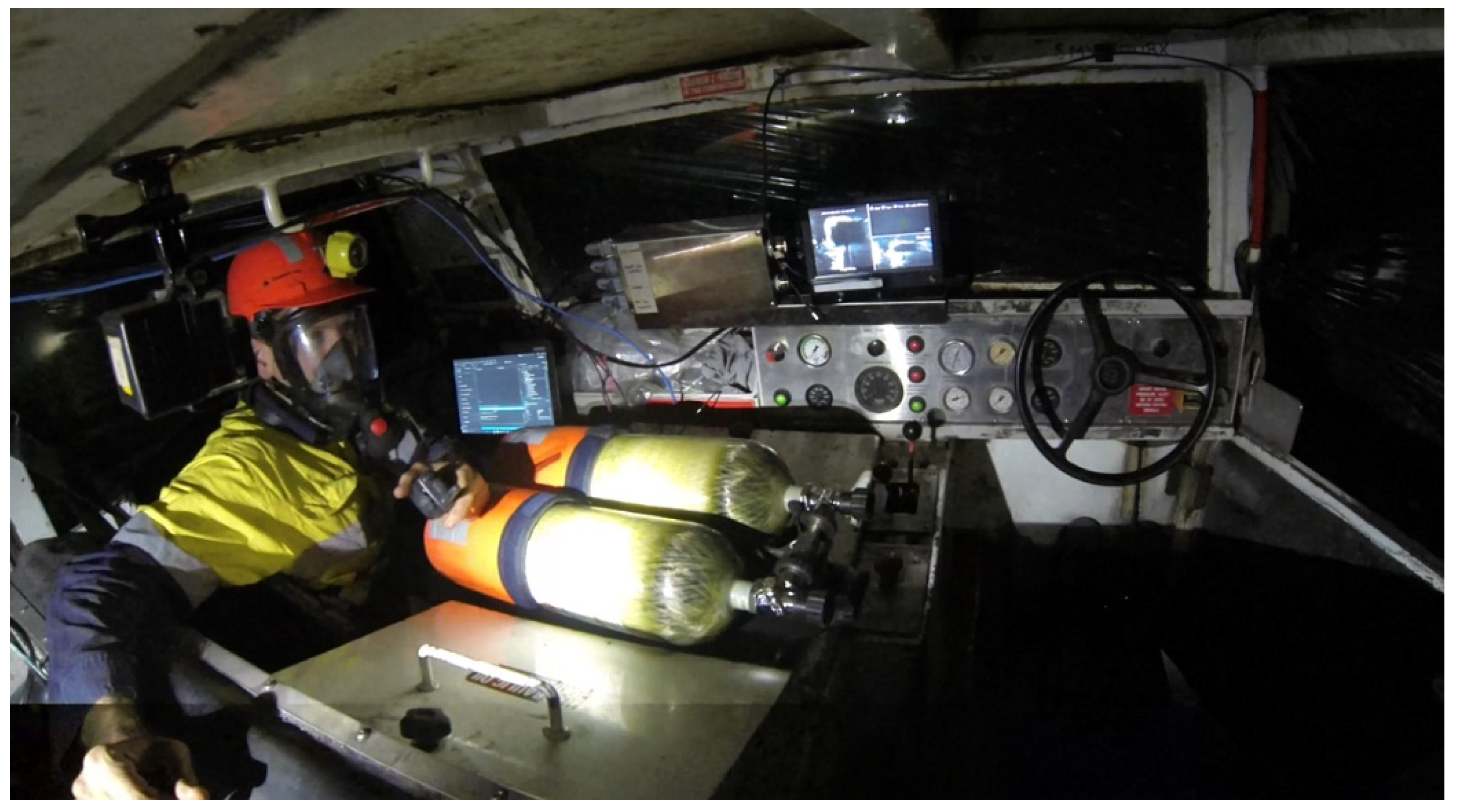
2.3. Underground Field Trials
The underground trial consisted of installation of the sensors on a Driftrunner mine personnel transport vehicle (Figure 9). The radar sensor was housed behind the dielectric face of a flameproof enclosure designed for this system. As the radar interface was, for this trial, restricted to a laptop computer, the test crew consisted of a driver and navigator; the latter held the laptop and provided the driver with assistance to interpret the real-time display.
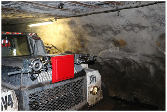
Figure 9.
Sensors mounted on a Driftrunner for the underground trial, radar behind red dielectric cover.
The test location consisted of a section of roadway, including a cut-through to allow for the detection of an adjacent tunnel and to test changing direction in conditions of limited to zero visibility. Multiple trials were carried out with the Driftrunner, comprising various test scenarios. These included:
- Functional testing of sensors while driving the vehicle along the roadway and around the corner, including the negotiation of an obstacle (large drum container) deliberately placed in the roadway.
- Trial of vehicle navigation using the sensors alone, along the same circuit as described. This was achieved by blacking out the windows of the vehicle with black plastic wrap.
- Repeat of the trial while stone-dusting the entire roadway to generate sufficient ambient dust to reduce visibility to effectively zero (Figure 10). During this trial, the operators were required to wear CABA due to the dust, while the windows of the vehicle remained blacked-out to ensure zero visibility (Figure 11).
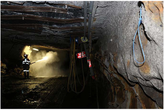 Figure 10. Stone-dusting the roadway in preparation for the final trials.
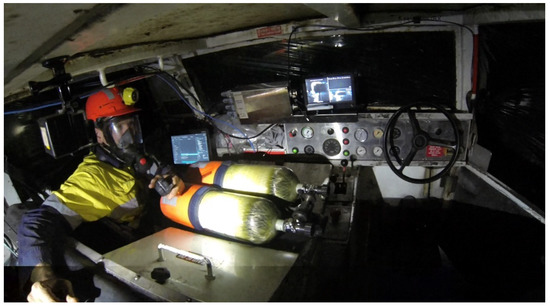 Figure 11. Inside the blacked-out Driftrunner prior to the final trial, navigator wearing CABA.
This final test scenario was repeated to provide a demonstration to industry partners at the conclusion of the field trial. The results from the mine site trials are presented in Section 3.
3. Results
3.1. Laboratory Test Results
The initial dust chamber tests with lidar and radar demonstrated that the laser-based technology would not be able to perform adequately once a sufficiently high level of smoke or dust was present in the local atmosphere. While the laser scanners performed well in the presence of white smoke, darker smoke and dust greatly attenuated the effective range, to approximately two metres for the single-echo lidar, and less than four metres for the multi-echo sensor. Furthermore, once sufficient dust settled on the surface of the flameproof enclosure, the range was effectively reduced to zero for both lidar systems [6]. For this reason, it was resolved to exclude lidars from the mine site trial as they could not be considered a reliable sensor for the emergency escape scenario.
The SWIR and LWIR cameras both provided improved performance when compared to the visible-light camera, although the thermal camera was markedly inferior to the SWIR system. This result was unexpected, since the longer wavelength technology should, in theory, perform better in a dusty environment. However, when there is insufficient thermal contrast in the target environment, the thermal system cannot discriminate between targets and the display is rendered ineffective. The SWIR system, on the other hand, is an active sensor that illuminates targets with short-wave infrared and detects the reflected light with the camera. For this reason, it was able to discriminate targets with reasonable effectiveness in the smoke but was ineffective in the dust. This is likely due to the fact that the dust particles, being much larger than the smoke, reflected much of the illuminating SWIR and effectively saturated the camera before any distance target could be illuminated.
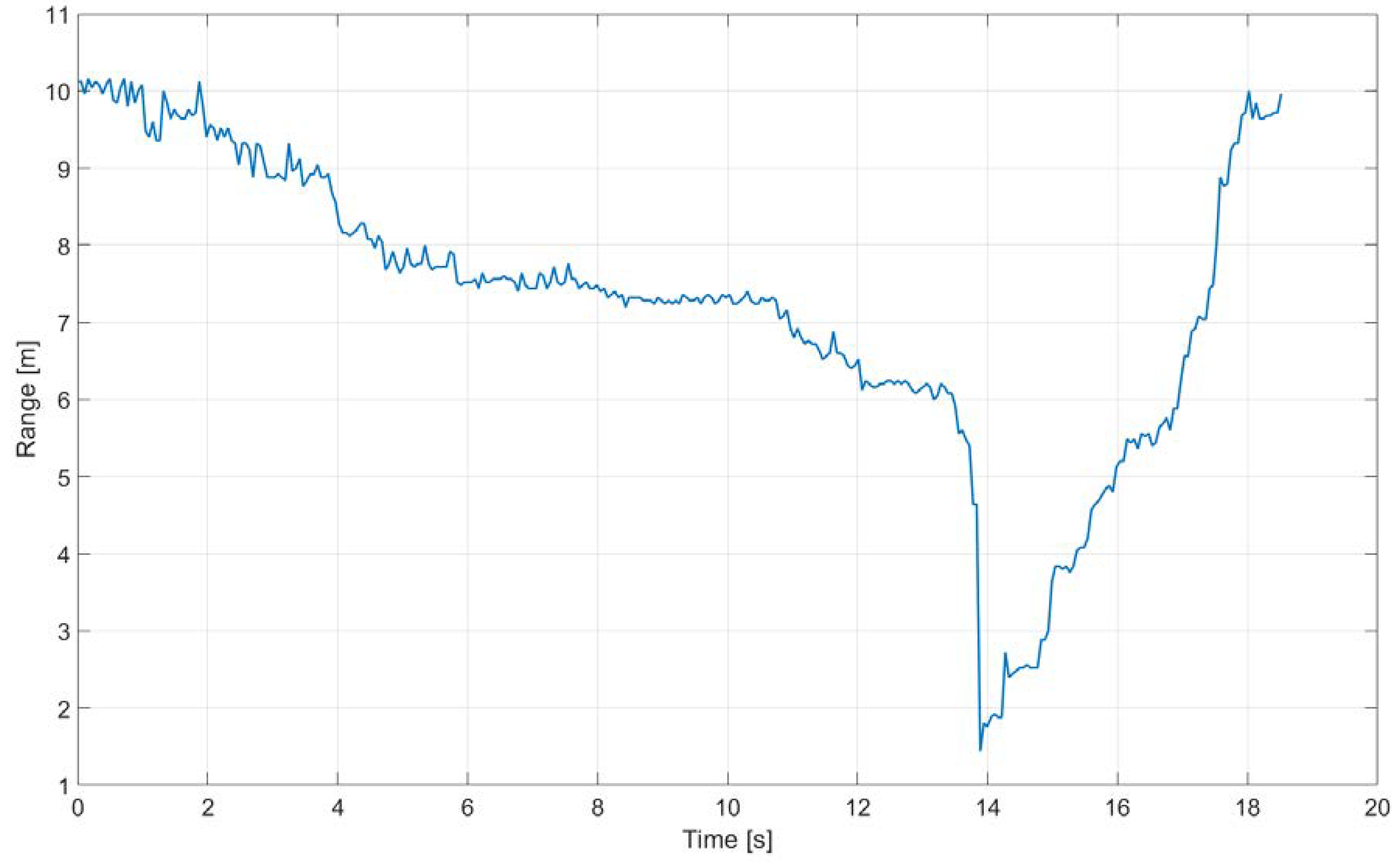
The radar sensor provided the best performance for all the sensors trialled. It was able to successfully track the target frame (see Figure 5) along the entire length of the dust chamber under all conditions, including the heaviest dust. The target range tracking result for the final dust test is shown in Figure 12, where the vertical axis indicates distance to the target and the horizontal axis represents elapsed time. The target started at the far end of the chamber (10 m distance from the radar) and was gradually moved to the mid-point of the room. It was then very rapidly moved to within half a metre of the radar (the blanking distance of the sensor) to demonstrate the sensor’s ability to handle highly dynamic environments, before being returned to the far end of the chamber.

Figure 12.
Radar target track for dust chamber results.
A summary of the test results for the dust chamber testing is shown in Table 3.
3.2. Underground Field Trial Results
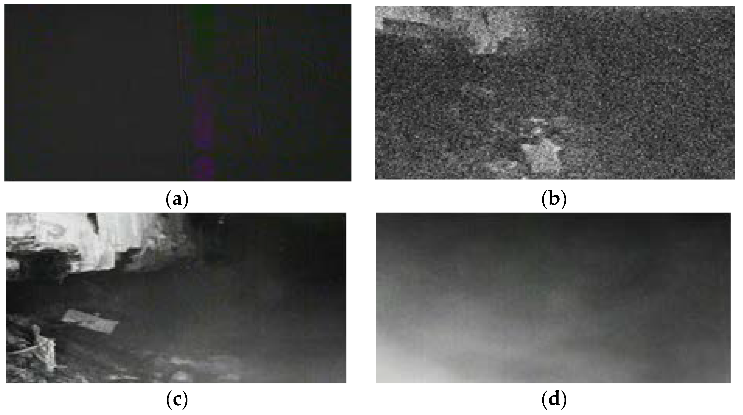
The mine site trial results confirmed the sensor performance predicted by the laboratory tests. The various cameras demonstrated the expected strengths and weaknesses previously identified. The thermal (LWIR) camera failed to provide any useful information due to the lack of thermal contrast in the roadway environment. The visible light camera provided a very grainy picture under conditions of no dust and limited background illumination from miner cap-lamps, but could not provide any vision without external lighting, nor penetrate any significant dust. The SWIR camera was able to provide excellent vision in a non-dusty environment, and still provided a reasonable picture at the start of the stone-dusting trial; once the dust level rose to a heavy level, however, the camera was rendered effectively blind due to reflections from the dust saturating the camera sensors. These results are summarized visually in Figure 13.
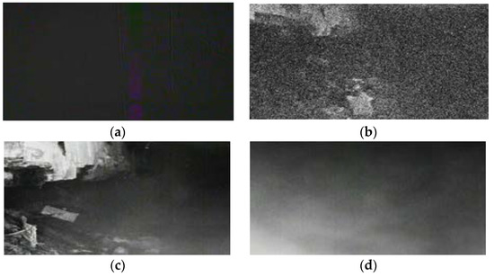
Figure 13.
(a) LWIR; (b) visible light; (c) SWIR low dust; (d) SWIR heavy dust.
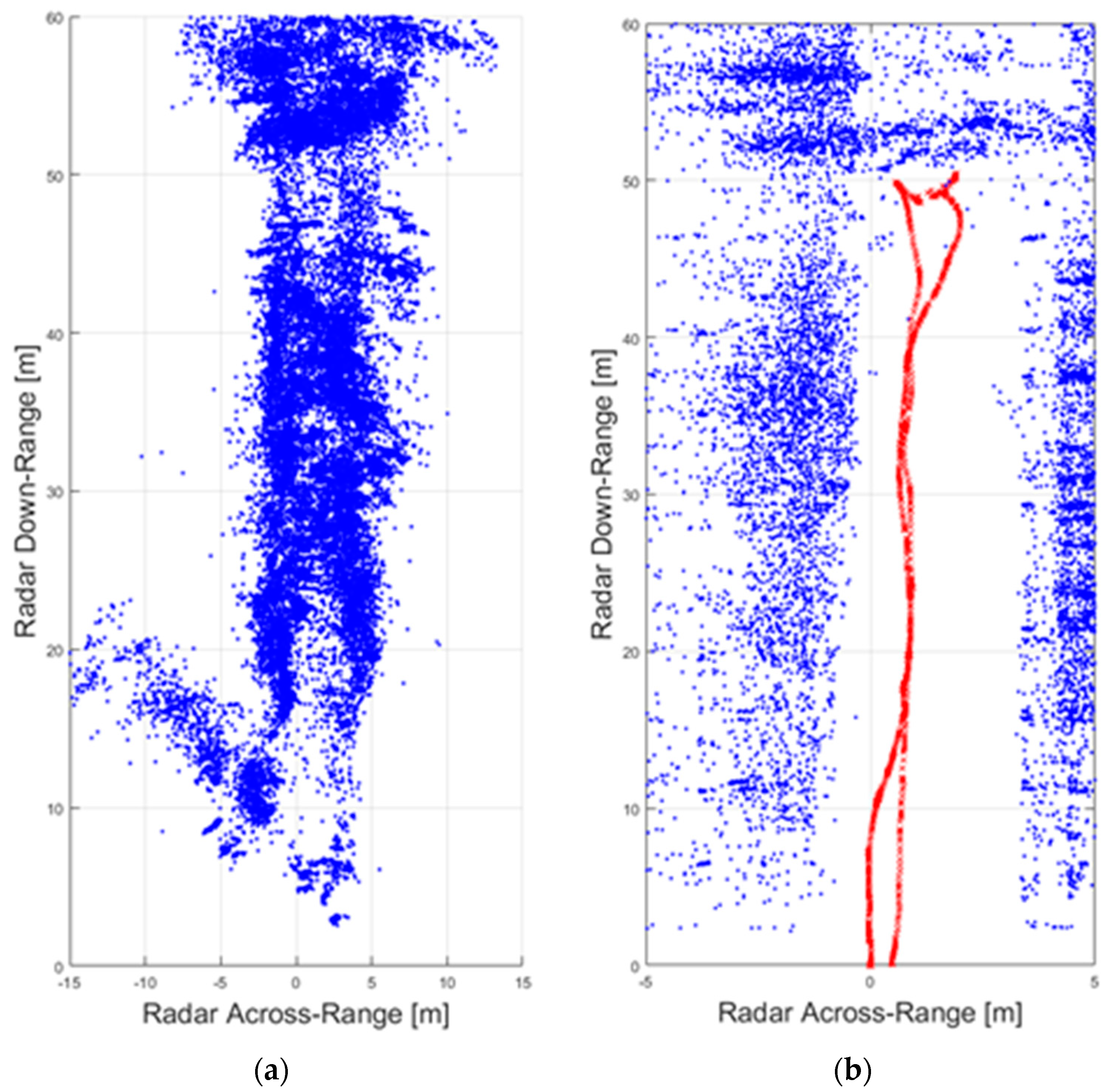
The radar sensor provided accurate target returns throughout all stages of testing, including during the heaviest dusting of the final trial in which it proved itself to be the only sensor capable of providing useful information for navigation. Using this sensor alone, the driver and navigator were able to guide the vehicle along the roadway, avoid the deliberately placed obstacle, and around the corner of the cut-through. The real-time interface provided the range to any large structures forward of the sensor (Figure 8), and also recorded all radar returns for the entire trial for later processing. These are shown in Figure 14, both the raw radar returns and a processed version showing persistent targets associated with the roadway walls, and overlaying the vehicle track in red. Note that the horizontal axis for Figure 14b is narrowed to focus only on the vicinity around the roadway, while the data for Figure 14a includes all radar target echoes within a 60 m downrange limit.

Figure 14.
(a) Raw radar returns for a complete trial run; (b) processed returns showing vehicle track (red).
4. Discussion
The results of the trial clearly demonstrate the efficacy of the radar sensor for providing vehicle guidance in a heavy-dust environment such as might be encountered during a mine emergency caused by fire or explosion. Nevertheless, interpreting the real-time radar data—as seen in the simple user interface prepared for this trial—presented a challenge for the operator, and more work is therefore required on the driver interface before the technology can be successfully transitioned to mine site use. The Australian coal industry has therefore sponsored a project to carry out the necessary ruggedization of the system hardware and software that will complete an additional, comprehensive, field testing regime. The hardware component of the work is focussed on developing a flexible installation package (based around the a new, transparent flameproof) that will allow the sensor itself to be integrated into a range of mining machines. The software component includes additional processing work to simplify the raw data by identifying and enhancing target features in the field of view, as well as development of a variety of operator interface options (including an investigation of audible and tactile feedback) to deliver a reliable driver interface under all conditions. The new software also introduces inferential processing algorithms that can suggest the location and extent of mine infrastructure features such as roadway ribs and cut-throughs. This information can then be correlated with mine plan data via an integrated digital management architecture, to provide a robust estimate of absolute location in the mine, even when communications systems are out of service (for example, during a mine escape scenario). At the conclusion of this project, the system will have been de-risked from a technical standpoint and have achieved a pre-commercial prototype level of readiness.
A smaller radar unit, operating at 77 GHz, has also been trialled as part of this project. Tests were carried out at Simtars; the 77 GHz unit performed similarly to the 26 GHz unit and operated effectively, even in the presence of heavy dust and smoke. However, the 77 GHz radar has the advantage of being approximately one-quarter the size of the other unit, so it can fit in the relatively small dielectrically-transparent flameproof enclosure, which weighs only 8 kg (Figure 15). This facilitates mounting the radar system on vehicles and other mobile equipment.
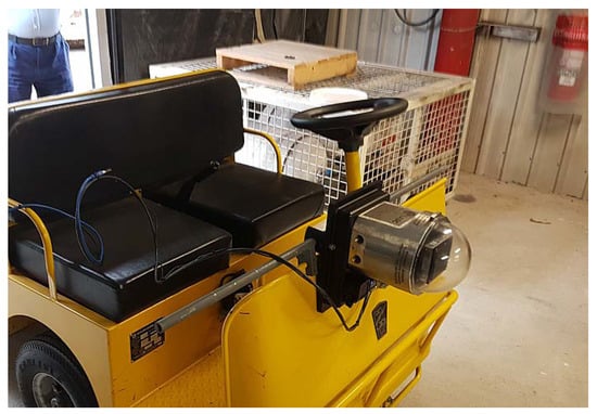
Figure 15.
New radar sensor mounted in the transparent flameproof for testing at Simtars.
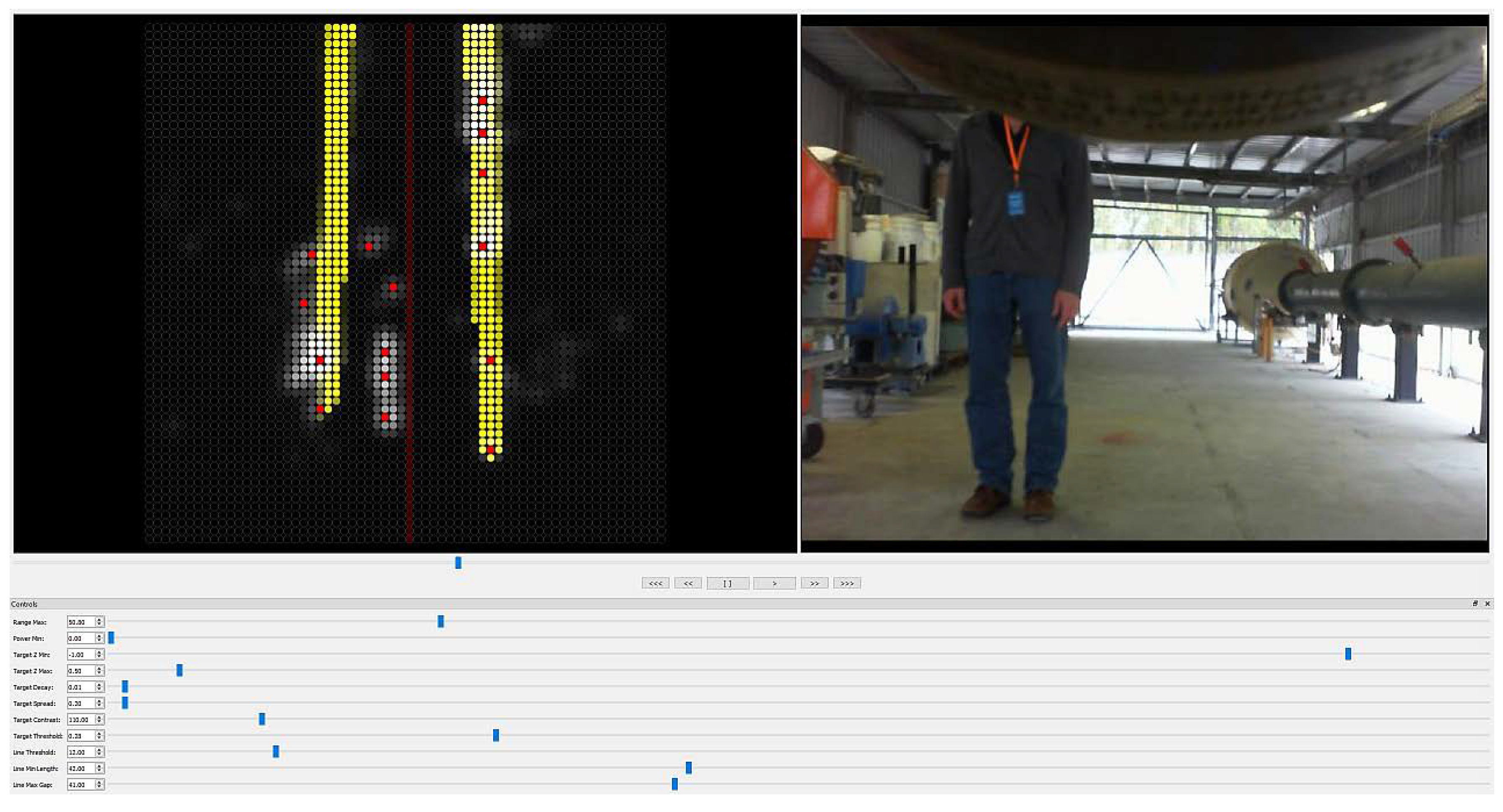
The new user interface features an inference system that tracks the persistence of objects and identifies approximately colinear elements in order to overlay an estimate of the roadway walls. This feature, together with improved display options for the management of current and persistent echoes provides a much richer user experience that dramatically improves the ability to navigate using the sensor. A typical display, together with matching camera vision, is shown in Figure 16, where the sides of the test location have been identified as edges in yellow, while an obstacle (a person standing in front of the slowly moving trolley) is identified as a line of red dots at the centre-left of the display.
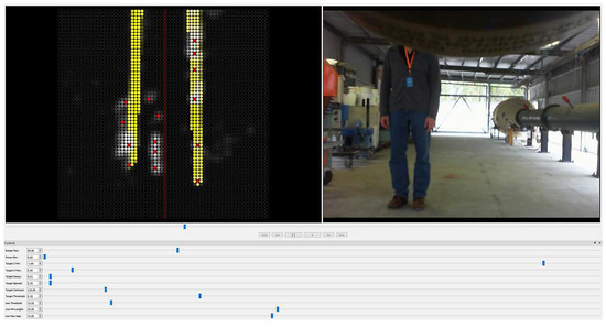
Figure 16.
Improved radar interface highlighting side-wall structures and a person acting as obstacle.
The completed system, including the new hardware and software components, will be trialled in an underground coal mine in the first quarter of 2020. While the driver for developing the mine machine radar sensor was the mine escape scenario, the potential application field for the radar sensor includes general mine machine guidance for equipment including shuttlecars, LHDs and continuous miners.
5. Conclusions
A mine machine radar sensor has been described. The system has proven to be successful at providing a robust guidance capability for a driver, even under circumstances of heavy dust and zero visibility. Ongoing work includes:
- The finalisation of the improved software system, including provision of adjustable user settings for object persistence and other relevant parameters
- Development of a LED-array version of the radar interface to provide a bright, high-contrast display for in-cab use in a mine transport vehicle
- Underground trials of the complete system in a suitable coal mine
- Finalisation of the system to a pre-commercial stage for uptake by the coal industry.
A sensor system that is certified for coal mine use and is capable of operation despite ambient and surface dust has potential applications beyond the emergency rescue scenario. As the industry moves toward greater use of automated guidance systems for mine machinery such as shuttle cars and continuous miners, a reliable sensor that can operate in conditions of heavy dust (such as are typically encountered during mining operations) is likely to be of significant value. A radar-based sensor is relatively immune to both ambient and surface dust, thus requiring less manual intervention (cleaning) than a laser-based technology [12]. For this reason, it is expected that navigation sensors similar to the one described herein will increasingly be valued as enabling technologies for the enhanced operation of the digital mine ecosystem.
Author Contributions
Conceptualization, Methodology, Software, Writing—Original Draft Creation, C.H. Project Administration, Investigation, Formal Analysis, Validation, Writing—Review and Editing, C.H., L.M., G.K., A.d.K. All authors have read and agreed to the published version of the manuscript.
Funding
Part of this research was funded by ACARP, grants C14024 and C27049.
Acknowledgments
The authors wish to thank the Australian coal industry, in particular ACARP, for supporting this research. They also acknowledge the support of the participating mine-site, and the software development work carried out by Alex Pitt and Paul McPhee (CSIRO).
Conflicts of Interest
The authors declare no conflict of interest.
References
- Windridge, F.W. Report on an accident at Moura No 2 Underground Mine on Sunday, 7 August 1994: Wardens inquiry conducted pursuant to Section 74 of “The Coal Mining Act, 1925”; Govt. Printer: Brisbane, Australia, 1996. [Google Scholar]
- Jakeman, M. Developments in self esacpe and aided rescue arising from the Moura No.2 Wardens Inquiry. In Proceedings of the Coal 1998: Coal Operators’ Conference, Wollongong, Australia, 18–20 February 1998. [Google Scholar]
- Queensland Government Natural Resources and Mines. Report on an Emergency Exercise at Kestrel Coal Mine 27 November 2001; Govt. Printer: Brisbane, Australia, 2001.
- Binnie, P.; Davis, R.; Watkinson, M. ACARP Report C14024: Mines Rescue Vehicle―Demonstration Phase; Australian Coal Research Limited: Brisbane, Australia, 2006. [Google Scholar]
- International Electrotechnical Commission. IECEx. IEC-IECEx. 2019. Available online: https://www.iecex.com/ (accessed on 15 June 2019).
- Kock, D.; Lihou, R. The evaluation of laser guidance systems for use on a self escape vehicle after an underground mine explosion. In Proceedings of the Queensland Mining Industry Safety and Health Conference, Townsville, Australia, 18–21 August 2013. [Google Scholar]
- Sieber, M.; Färber, B. Driver perception and reaction in collision avoidance: Implications for ADAS development and testing. In Proceedings of the 2016 IEEE Intelligent Vehicles Symposium (IV), Gothenburg, Sweden, 19–22 June 2016. [Google Scholar]
- FLIR. Support for PathFindIR II. FLIR. Available online: https://www.flir.com/support/products/pathfindir-ii#Specifications (accessed on 11 January 2020).
- SICK. SICK LD-MRS400001 Online Data Sheet. 2019. Available online: https://cdn.sick.com/media/pdf/5/55/355/dataSheet_LD-MRS400001_1045046_en.pdf (accessed on 11 January 2020).
- Kosowsky, L.H.; Aronoff, A.D.; Ferraro, R.; Alland, S.; Fleischman, E. 77 GHz Radar for First Responders. In Proceedings of the SPIE, San Francisco, CA, USA, 28 January–2 February 2017; Volume 10103. [Google Scholar]
- smartMicro Radar, Data Sheet| MRR Type 39|Automotive Sensor. 01 07 2015. Available online: http://www.smartmicro.de/fileadmin/user_upload/Documents/Automotive/UMRRTrafficSensorType39DataSheet.pdf (accessed on 21 May 2019).
- Hargrave, C.O.; Bialkowski, M. Scanning Radar System for Machine Guidance. In Machine Vision and Mechatronics in Practice; Springer: Berlin/Heidelberg, Germany, 2015; pp. 11–21. [Google Scholar]


© 2020 by the authors. Licensee MDPI, Basel, Switzerland. This article is an open access article distributed under the terms and conditions of the Creative Commons Attribution (CC BY) license (http://creativecommons.org/licenses/by/4.0/).