An Analysis of Waste Heat Recovery from Wastewater on Livestock and Agriculture Farms


Abstract
1. Introduction
- heating utility water for technological purposes in food production technologies and for sanitary purposes in households;
- heating utility water for irrigation of plants produced under cover;
- heating utility water in livestock buildings for watering and preparing animal feed;
- heating air in drying equipment and vegetable and fruit storage rooms.
2. Test Object and Input Data
3. Variants
- Variant I—heating of water used for cleaning stands, watering and preparing feed for pigs;
- Variant II—heating water for irrigation in plant production;
- Variant III—drying of cereals;
- Variant IV—preparation of hot utility water for the breeder’s residential building.
3.1. Variant I
3.2. Variant II
3.3. Variant III
3.4. Variant IV
4. Methods
- qsrd—average daily demand for hot utility water, L/day,
- te—the time of using hot water for specific purposes, h.
- cw—specific heat of water, J/kgK,
- Tz—heated water temperature, K,
- Tn—municipal water temperature, K.
- Gp—initial mass of moist material, kg,
- wp—initial moisture of material, %,
- wk—final moisture of material, %.
- xw—moisture content in the air after the drying process, g/kg,
- xz—moisture content in the air before the drying process, g/kg.
- iw—specific enthalpy of air after the drying process, kJ/kg,
- iz—specific air enthalpy before drying, kJ/kg.
- W—amount of moisture removed, kg/h,
- q—proper heat consumption, kJ/kg.
- Q—calculated demand for thermal power for preparing hot utility water, process water or drying agricultural products, kW,
- tz—tank utilization time (heat pump standstill), h.
- Qd—thermal power obtained from a low-temperature source, determined by the heat pump manufacturer, kW,
- qe—specific heat output taken from the ground, W/m2.
- p—discount rate, %,
- N—calculated service life of the facility, years.
- rce—rate of fixed operating costs, %; 2% adopted as proposed by Kusto [46].
- Krr—total capital return costs, €/year,
- Kest—the sum of fixed operating costs, €/year,
- Kinpc—total capital expenditure on a heat pump installation; €.
- Qpc—heat pump installed power, kW,
- Tipc—heat pump installed power usage time, h/year,
- cel—electricity price, €/kWh,
- kmr—cost factor of moving materials for the heat pump, -; 1.02 adopted according to the Kusto proposals [46],
- φ—average annual heating efficiency factor,
- ηsil—efficiency of the electric motor driving the heat pump compressor, annual average value, %; 85% were adopted as Kusto proposed [46].
- O—reduction of costs of obtaining heat for heating hot water for 1 kWh in relation to the cost of electricity, €/kWh,
- Qapc—the amount of useful heat supplied per year by the heat pump, kWh/year.
5. Results and Discussion
6. Conclusions
Author Contributions
Funding
Conflicts of Interest
References
- Von Cossel, M.; Wagner, M.; Lask, J.; Magenau, E.; Bauerle, A.; Von Cossel, V.; Warrach-Sagi, K.; Elbersen, B.; Staritsky, I.; Van Eupen, M.; et al. Prospects of Bioenergy Cropping Systems for A More Social-Ecologically Sound Bioeconomy. Agronomy 2019, 9, 605. [Google Scholar] [CrossRef]
- Sapkota, T.B.; Vetter, S.H.; Jat, M.L.; Sirohi, S.; Shirsath, P.B.; Singh, R.; Jat, H.S.; Smith, P.; Hillier, J.; Stirling, C.M. Cost-effective opportunities for climate change mitigation in Indian agriculture. Sci. Total Environ. 2019, 655, 1342–1354. [Google Scholar] [CrossRef] [PubMed]
- Dubey, P.K.; Singh, G.S.; Abhilash, P.C. Agriculture in a Changing Climate. In Adaptive Agricultural Practices: Building Resilience in a Changing Climate; Springer International Publishing: New York, NY, USA, 2020; pp. 1–10. [Google Scholar]
- Perez, I.A.V.; Toral, J.N.; Vazquez, A.T.P.; Hernandez, F.G.; Ferrer, G.J.; Cano, D.G. Potential for organic conversion and energy efficiency of conventional livestock production in a humid tropical region of Mexico. J. Clean. Prod. 2019, 241, 118354. [Google Scholar] [CrossRef]
- Directive 2009/28/EC of the European Parliament and of the Council of 23 April 2009 on the Promotion of the Use of Energy from Renewable Sources and Amending and Subsequently Repealing Directives 2001/77/EC and 2003/30/EC (Text with EEA Relevance). Available online: https://eur-lex.europa.eu/legal-content/EN/ALL/?uri=CELEX:32009L0028 (accessed on 18 December 2019).
- Directive 2009/29/EC of the European Parliament and of the Council of 23 April 2009 Amending Directive 2003/87/EC so as to Improve and Extend the Greenhouse Gas Emission Allowance Trading Scheme of the Community. Available online: https://eur-lex.europa.eu/LexUriServ/LexUriServ.do?uri=OJ:L:2009:140:0063:0087:en:PDF (accessed on 18 December 2019).
- Directive 2012/27/EU of the European Parliament and of the Council of 25 October 2012 on Energy Efficiency, Amending Directives 2009/125/EC and 2010/30/EU and Repealing Directives 2004/8/EC and 2006/32/EC Text with EEA Relevance. Available online: https://eur-lex.europa.eu/legal-content/EN/TXT/?uri=celex%3A32012L0027 (accessed on 18 December 2019).
- Sugiawan, Y.; Managi, S. New evidence of energy-growth nexus from inclusive wealth. Renew. Sustain. Energy Rev. 2019, 103, 40–48. [Google Scholar] [CrossRef]
- Bastida, L.; Cohen, J.J.; Kollmann, A.; Moya, A.; Reichl, J. Exploring the role of ICT on household behavioral energy efficiency to mitigate global warming. Renew. Sustain. Energy Rev. 2019, 103, 455–462. [Google Scholar] [CrossRef]
- Kordana, S.; Pochwat, K.; Słyś, D.; Starzec, M. Opportunities and Threats of Implementing Drain Water Heat Recovery Units in Poland. Resources 2019, 8, 88. [Google Scholar] [CrossRef]
- Pochwat, K.; Kordana, S.; Starzec, M.; Słyś, D. Comparison of two-prototype near-horizontal Drain Water Heat Recovery units on the basis of effectiveness. Energy 2019, 173, 1196–1207. [Google Scholar] [CrossRef]
- Spriet, J.; McNabola, A. Decentralized drain water heat recovery from commercial kitchens in the hospitality sector. Energy Build. 2019, 194, 247–259. [Google Scholar] [CrossRef]
- Antoneli, V.; Mosele, A.C.; Bednarz, J.A.; Pulido-Fernández, M.; Lozano-Parra, J.; Keesstra, S.D.; Rodrigo-Comino, J. Effects of Applying Liquid Swine Manure on Soil Quality and Yield Production in Tropical Soybean Crops (Paraná, Brazil). Sustainability 2019, 11, 3898. [Google Scholar] [CrossRef]
- Risberg, K.; Cederlund, H.; Pell, M.; Arthurson, V.; Schnürer, A. Comparative characterization of digestate versus pig slurry and cow manure—Chemical composition and effects on soil microbial activity. Waste Manag. 2017, 61, 529–538. [Google Scholar] [CrossRef]
- Font-Palma, C. Methods for the Treatment of Cattle Manure—A Review. C J. Carbon Res. 2019, 5, 27. [Google Scholar] [CrossRef]
- Szogi, A.A.; Vanotti, M.B.; Ro, K.S. Methods for Treatment of Animal Manures to Reduce Nutrient Pollution Prior to Soil Application. Curr. Pollut. Rep. 2015, 1, 47–56. [Google Scholar] [CrossRef]
- Ondrejka Harbulakova, V.; Estokova, A.; Kovalcikova, M. Correlation Analysis between Different Types of Corrosion of Concrete Containing Sulfate Resisting Cement. Environments 2017, 4, 44. [Google Scholar] [CrossRef]
- Smurzyńska, A.; Dach, J.; Czekała, W. Technologies to reduce emissions of noxious gases resulting from livestock farming. Inżynieria Ekol. 2016, 47, 189–198. [Google Scholar]
- Donham, K.J.; Yeggy, J.; Dague, R.R. Production rates of toxic gases from liquid swine manure: Health implications for workers and animals in swine confinement buildings. Biol. Wastes 1988, 24, 161–173. [Google Scholar] [CrossRef]
- Chen, J.; Ma, C.; Ji, X.; Lu, X.; Wang, C. Mechanism Study of Waste Heat Recovery from Slurry by Surface Scraped Heat Exchanger. Energy Procedia 2017, 105, 1109–1115. [Google Scholar] [CrossRef]
- Gheorghe, L.; Pană, C.; Mihaescu, L.; Cernat, A.; Negurescu, N.; Mocanu, R.; Negreanu, G. Solutions for energy recovery of animal waste from leather industry. Energy Convers. Manag. 2017, 149, 1085–1095. [Google Scholar]
- Have, H.; Fritze, M. Heat Energy from Animal Waste by Combined Drying, Combustion and Heat Recovery. In Energy from Biomass; Springer: Dordrecht, The Netherlands, 1981. [Google Scholar] [CrossRef]
- Pati, J.; Hotta, S. Effect of Waste Heat Recovery on Drying Characteristics of Sliced Ginger in a Natural Convection Dryer. Procedia Eng. 2015, 105, 145–152. [Google Scholar] [CrossRef]
- Liu, Y.M.; Chang, K.C.; Lin, W.M.; Chung, K.M. Solar thermal application for the livestock industry in Taiwan. Case Stud. Therm. Eng. 2015, 6, 251–257. [Google Scholar] [CrossRef]
- Nemś, A.; Nemś, M.; Świder, K. Analysis of the Possibilities of Using a Heat Pump for Greenhouse Heating in Polish Climatic Conditions—A Case Study. Sustainability 2018, 10, 3483. [Google Scholar] [CrossRef]
- Deglin, D.; Caenegem, L.; Dehon, P. Subsoil Heat Exchangers for the Air Conditioning of Livestock Buildings. J. Agric. Eng. Res. 1999, 73, 179–188. [Google Scholar] [CrossRef]
- Feru, E.; Willems, F.; Jager, B.; Steinbuch, M. Modeling and Control of a Parallel Waste Heat Recovery System for Euro-VI Heavy-Duty Diesel Engines. Energies 2015, 7, 6571–6592. [Google Scholar] [CrossRef]
- Kalinichenko, A.; Havrysh, V.; Hruban, V. Heat Recovery Systems for Agricultural Vehicles: Utilization Ways and Their Efficiency. Agriculture 2018, 8, 199. [Google Scholar] [CrossRef]
- Valencia, G.; Fontalvo, A.; Cardenas, E.Y.; Duarte, J.; Isaza-Roldan, C. Energy and Exergy Analysis of Different Exhaust Waste Heat Recovery Systems for Natural Gas Engine Based on ORC. Energies 2019, 12, 2378. [Google Scholar] [CrossRef]
- Martinho, V.J.P.D. Energy consumption across European Union farms: Efficiency in terms of farming output and utilized agricultural area. Energy 2016, 103, 543–556. [Google Scholar] [CrossRef]
- Vellenga, L.; Qualitz, G.; Drastig, K. Farm Water Productivity in Conventional and Organic Farming: Case Studies of Cow-Calf Farming Systems in North Germany. Water 2018, 10, 1294. [Google Scholar] [CrossRef]
- Olkowski, A.A. Livestock Water Quality: A Field Guide for Cattle, Horses, Poultry and Swine; Agriculture and Agri-Food, University of Saskatchewan: Saskatoon, SK, Canada, 2009. [Google Scholar]
- Rennie, T.J.; Gordon, R.J.; Smith, W.N.; VanderZaag, A.C. Liquid manure storage temperature is affected by storage design and management practices—A modelling assessment. Agric. Ecosyst. Environ. 2018, 260, 47–57. [Google Scholar] [CrossRef]
- Widiatmojo, A.; Chokchai, S.; Takashima, I.; Uchida, Y.; Yasukawa, K.; Chotpantarat, S.; Charusiri, P. Ground-Source Heat Pumps with Horizontal Heat Exchangers for Space Cooling in the Hot Tropical Climate of Thailand. Energies 2019, 12, 1274. [Google Scholar] [CrossRef]
- Nxawe, S.; Ndakidemi, P.; Laubscher, C.P. Possible effects of regulating hydroponic water temperature on plant growth, accumulation of nutrients and other metabolites. Afr. J. Biotechnol. 2011, 9, 9128–9134. [Google Scholar]
- Golher, D.; Thirumurugan, P.; Patel, B.; Upadhyay, V. Effect of drinking water temperature on water intake, feed intake and milk production of crossbred dairy cattle at high altitude temperate Himalayas. Indian J. Anim. Sci. 2014, 84, 1101–1104. [Google Scholar]
- Nikolaou, G.; Neocleous, D.; Katsoulas, N.; Kittas, C. Irrigation of Greenhouse Crops. Horticulturae 2019, 5, 7. [Google Scholar] [CrossRef]
- Franco-Luesma, S.; Álvaro-Fuentes, J.; Plaza-Bonilla, D.; Arrúe, J.L.; Cantero-Martínez, C.; Cavero, J. Influence of irrigation time and frequency on greenhouse gas emissions in a solid-set sprinkler-irrigated maize under Mediterranean conditions. Agric. Water Manag. 2019, 221, 303–311. [Google Scholar] [CrossRef]
- Tekin, Z.H.; Baslar, M.; Karasu, S.; Kilicli, M. Dehydration of green beans using ultrasound-assisted vacuum drying as a novel technique: drying kinetics and quality parameters. J. Food Process. Preserv. 2017, 41, 6. [Google Scholar] [CrossRef]
- Le Riche, E.; VanderZaag, A.; Burtt, S.; Lapen, D.; Gordon, R. Water Use and Conservation on a Free-Stall Dairy Farm. Water 2017, 9, 977. [Google Scholar] [CrossRef]
- Corson, M.; Doreau, M. Assessment of water use by livestock. Prod. Anim. 2013, 26, 239–248. [Google Scholar]
- Stec, A.; Słyś, D. Effect of development of the town of Przemyśl on operation of its sewerage system. Ecol. Chem. Eng. S 2013, 20, 381–396. [Google Scholar] [CrossRef]
- Kebebe, E.G.; Oosting, S.J.; Haileslassie, A.; Duncan, A.J.; Boer, I.J.M. Strategies for improving water use efficiency of livestock production in rain-fed systems. Animal 2015, 9, 908–916. [Google Scholar] [CrossRef]
- Kęskiewicz, P.; Śniechowska, B.; Danielewicz, J. Heat pumps in comparison to other energy sources in terms of economic efficiency, taking into account total estimated investments and operating cost. Instal 2012, 2, 27–31. [Google Scholar]
- Kusto, Z. Selected Aspects of Heat Pumps Effectiveness in Thermal Industry. Zeszyty Naukowe Politechniki Rzeszowskiej Budownictwo i Inżynieria Środowiska 2012, 53, 501–514. [Google Scholar]
- Kusto, Z. Incremental cost method in cost-efficiency evaluation of investment in distributed generation. Acta Energ. 2010, 3, 43–53. [Google Scholar]
- Kordana, S. SWOT analysis of wastewater heat recovery systems application. E3S Web Conf. 2017, 17, 00042. [Google Scholar] [CrossRef]
- How much coal is required to run a 100-watt light bulb 24 hours a day for a year? Available online: https://science.howstuffworks.com/environmental/energy/question481.htm (accessed on 18 December 2019).
- Foxell, S. Carbon Primer for the Built Environment; Routledge: New York, NY, USA, 2014. [Google Scholar]
- Określanie wielkości emisji zanieczyszczeń do powietrza towarzyszących eksploatacji złóż ropy naftowej i gazu ziemnego metodą wskaźnikową. Available online: http://archiwum.inig.pl/INST/nafta-gaz/nafta-gaz/Nafta-Gaz-2017-04-09.pdf (accessed on 18 December 2019).
- Wskaźniki emisji zanieczyszczeń powietrza emitowanych z indywidualnych źródeł ciepła. Available online: http://czysteogrzewanie.pl/wp-content/uploads/2013/02/Wskaźniki-emisji-zanieczyszczeń-powietrza-emitowanych-z-indywidualnych-źródeł-ciepła-Raport.pdf (accessed on 18 December 2019).


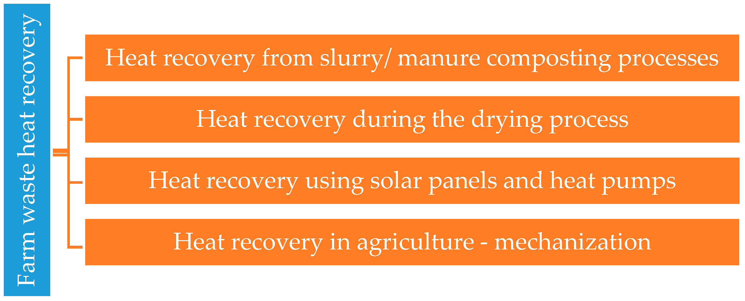
| Heat Recovery Area | Aim of Research | Author |
|---|---|---|
| Heat recovery from slurry/manure composting processes | The authors of the paper focused on analyzing the possibilities of waste heat recovery from discharged slurry which can be used to improve the efficiency of biogas production. In the research, the authors focus on energy recovery from waste of animal/agricultural origin. The research focused on replacing conventional energy sources to reduce the use of non-renewable raw materials. In their research, the authors analyzed the efficiency of the conversion system that allows obtaining waste heat energy from animal excrements from combined drying and combustion processes. | Chen, J.; Ma, C.; Ji, X.; Lu, X.; Wang, C. [20] Gheorghe, L.; Pană, C.; Mihaescu, L.; Cernat, A.; Negurescu, N.; Mocanu, R.; Negreanu, G. [21] Have, H.; Fritze, M. [22] |
| Heat recovery during the drying process | An analysis of heat recovery efficiency in drying processes. In the research the authors analyzed the amount of waste heat recovered from the ginger drying process in a biomass convection dryer with heat storage material (SHSM) and phase change material (PCM) | Pati, J.; Hotta, S. [23] |
| Heat recovery using solar panels and heat pumps | The research showed significant financial savings related to the use of renewable energy through solar panels. The authors of the study attempted to assess the selection of the heat source for the greenhouse facility on farms. Their research showed that the use of heat pumps could be considered a competitive method of heating greenhouse facilities due to greater economic efficiency and in relation to environmental protection. In the research, the authors made a 3D model of a ground heat exchanger. The simulations carried out confirmed the legitimacy of using this type of facilities in agriculture. | Liu, Y.M.; Chang, K.C.; Lin, W.M.; Chung, K.M. [24] Nemś, A.; Nemś, M.; Świder, K. [25] Deglin, D.; Caenegem, L.; Dehon, P. [26] |
| Heat recovery in agriculture—mechanization | Development of a heat recovery model from Euro VI class internal combustion engines, enabling an increase in waste energy recovery efficiency by 15%. | Feru, E.; Willems, F.; Jager, B.; Steinbuch, M. [27] |
| The article examined the technical and economic possibilities of heat recovery from agricultural machinery. The article demonstrated the economic legitimacy of using waste heat in agricultural machinery, especially in winter periods to reduce fuel consumption. An analysis of the use of the Organic Rankine Cycle (ORC)—a technology of converting medium and low-quality waste heat into mechanical energy and electricity in natural gas engines. Actions taken were aimed at reducing fuel consumption, thus reducing the operating costs of mechanical devices in agriculture and environmental protection by improving air quality. | Kalinichenko, A.; Havrysh, V.; Hruban, V. [28] Valencia, G.; Fontalvo, A.; Cardenas E.,Y.; Duarte, J.; Isaza-Roldan, C. [29] |
| Input Data | Type of Data | Value |
|---|---|---|
| Construction data | a livestock building area | 600 m2 |
| a livestock building high | 6 m | |
| a monolithic underground slurry tank capacity | 450 m3 | |
| a dryer area | 51 m2 | |
| a greenhouse area | 1000 m2 | |
| Design parameters of the system cooperating with the heat pump | number of inhabitants in the household, M | 6 |
| number of piglet breeding places | 400 | |
| demand for water for cleaning stands, watering and preparing feed for pigs, qśr d1 | 4000 L/day | |
| water demand for plant production, qśr d2 | 5000 L/day | |
| water demand for a residential building, qśr d3 | 660 L/day | |
| system operation time per day | 18 h | |
| coefficient of hourly irregular distribution of water | 2.5 | |
| municipal water temperature, Tz | 10 °C | |
| water temperature for cleaning stands, watering and preparing animal feed, Tp (variant I), | 60 °C | |
| irrigation water temperature, Tn (variant II), | 20 °C | |
| water supply temperature to the water air heater, Tz (variant III), | 55 °C | |
| DHW temperature, Tc (variant IV), | 50 °C | |
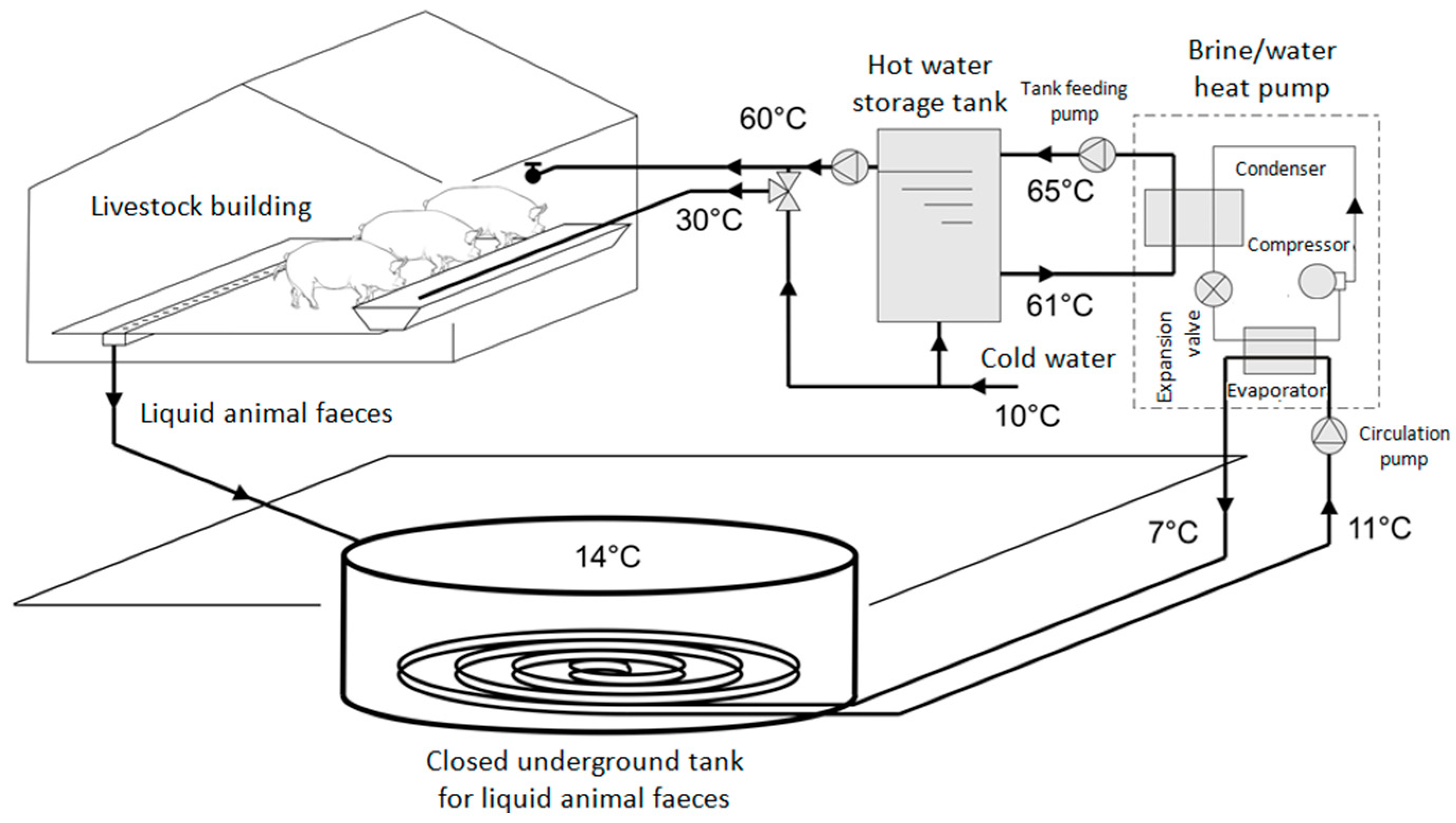
| lower heat source—sewage at a temperature of Tść (average sewage temperature) [19,23], | 14 °C | |
| specific heat of water, cw | 4174 J/kg∙K | |
| Input data for economic analysis | system life, which corresponds to the time of trouble-free operation of heat pump compressors, was assumed at, N | 20 years |
| discount rate, p | 6% | |
| electricity price, cel | 0.14 €/kWh |
| Variant I | Variant II | Variant IV | |
|---|---|---|---|
| Number of inhabitants in the household (person) | 6 | 6 | 6 |
| Average daily demand for hot water qśr d (L/day) | 4000 | 5000 | 660 |
| Average hourly hot water demand qśr h (L/h) | 222.2 | 714.3 | 36.7 |
| Average power of the utility hot water system Qśr h (kW) | 12.8 | 8.3 | 17 |
| Maximum hourly utility hot water demand qmax h (L/h) | 555.6 | n/a | 220.7 |
| Maximum power of the utility hot water system Qmax h (kW) | 31.9 | n/a | 10.2 |
| Reduction factor ψ (-) | 0.73 | 0.77 | 0.36 |
| Reduced system power for preparing utility hot water Qz (kW) | 26.1 | 7.1 | 4.1 |
| Variant III | |
|---|---|
| Initial weight of wet material Gp (kg) | 7140 |
| Amount of moisture removed W (kg/h) | 49.6 |
| Appropriate dry air consumption l (kg/kg moisture drain) | 166.7 |
| Air flow rate L (kg/h) | 8263.9 |
| Specific heat consumption q (kJ/kg moisture drain) | 2533.3 |
| Heat flow rate Q (kJ/h) | 125,611.1 |
| Calculated system power for preparing hot process water Qz (kW) | 34.9 |
| Variant I | Variant II | Variant III | Variant IV | |
|---|---|---|---|---|
| Calculated system power for utility hot water and process water Q (kW) | 26.1 | 7.1 | 34.89 | 4.1 |
| Storage time tz (h) | 9 | 1 | n/a | 9 |
| Calculated heat output of heat pump Qpc (kW) | 41.7 | 8.2 | 34.9 | 6.6 |
| Selected heat pump | Dimplex SIH 40TE | STIEBEL ELTRON WPF 5 | STIEBEL ELTRON WPF 27 | Viessmann Vitocal 200-G |
| Heating capacity of the pump Qpc’ (kW) | 44.0 | 8.4 | 35.5 | 7.0 |
| Cooling capacity Qd (kW) | 29.3 | 7.2 | 26.2 | 5.0 |
| Electric power consumption P (kW) | 14.7 | 1.2 | 9.3 | 2.0 |
| Coefficient of performance COP (-) | 2.8 | 7.5 | 3.7 | 3.3 |
| Length of sewage heat exchanger Lw (m) | 732.5 | 180 | 655 | 125 |
| Variant I | Variant II | Variant III | Variant IV | |
|---|---|---|---|---|
| Heat pump (€) | 14,750 | 4040 | 9865 | 4950 |
| Heat exchanger (€) | 8780 | 2335 | 7660 | 1775 |
| Other elements of the installation: hot water tank, pipelines, fittings, automation system as well as labor and commissioning of the installation (€) | 5882.5 | 1593.75 | 4381.25 | 1681.25 |
| Total investments Kinpc (€) | 29,412.5 | 7968.75 | 21,906.25 | 8406.25 |
| Variant I | Variant II | Variant III | Variant IV | |
|---|---|---|---|---|
| Capital return installment r | 0.0872 | 0.0872 | 0.0872 | 0.0872 |
| Installment of fixed costs r + rce | 0.107 | 0.107 | 0.107 | 0.107 |
| Annual fixed costs Krst (€/year) | 3157.49 | 855.12 | 2351.21 | 903.25 |
| Annual variable operating costs Kezm (€/year) | 14,265.41 | 235.29 | 4658.03 | 1925.64 |
| Annual costs of heat generation Krpc (€/year) | 17,422.90 | 1088.07 | 7009.25 | 2828.89 |
| Amount of useful heat Qapc (kWh/year) | 240,900 | 10,642.8 | 103,944 | 38,325 |
| Unit cost of heat generated qpc (€/kWh) | 0.07 | 0.10 | 0.07 | 0.07 |
| Reduction in the cost of obtaining heat O (€/year) for 1 kWh | 0.07 | 0.04 | 0.07 | 0.07 |
| Financial savings ΔK (€/year) | 15,863.04 | 380.14 | 7353.02 | 2466.60 |
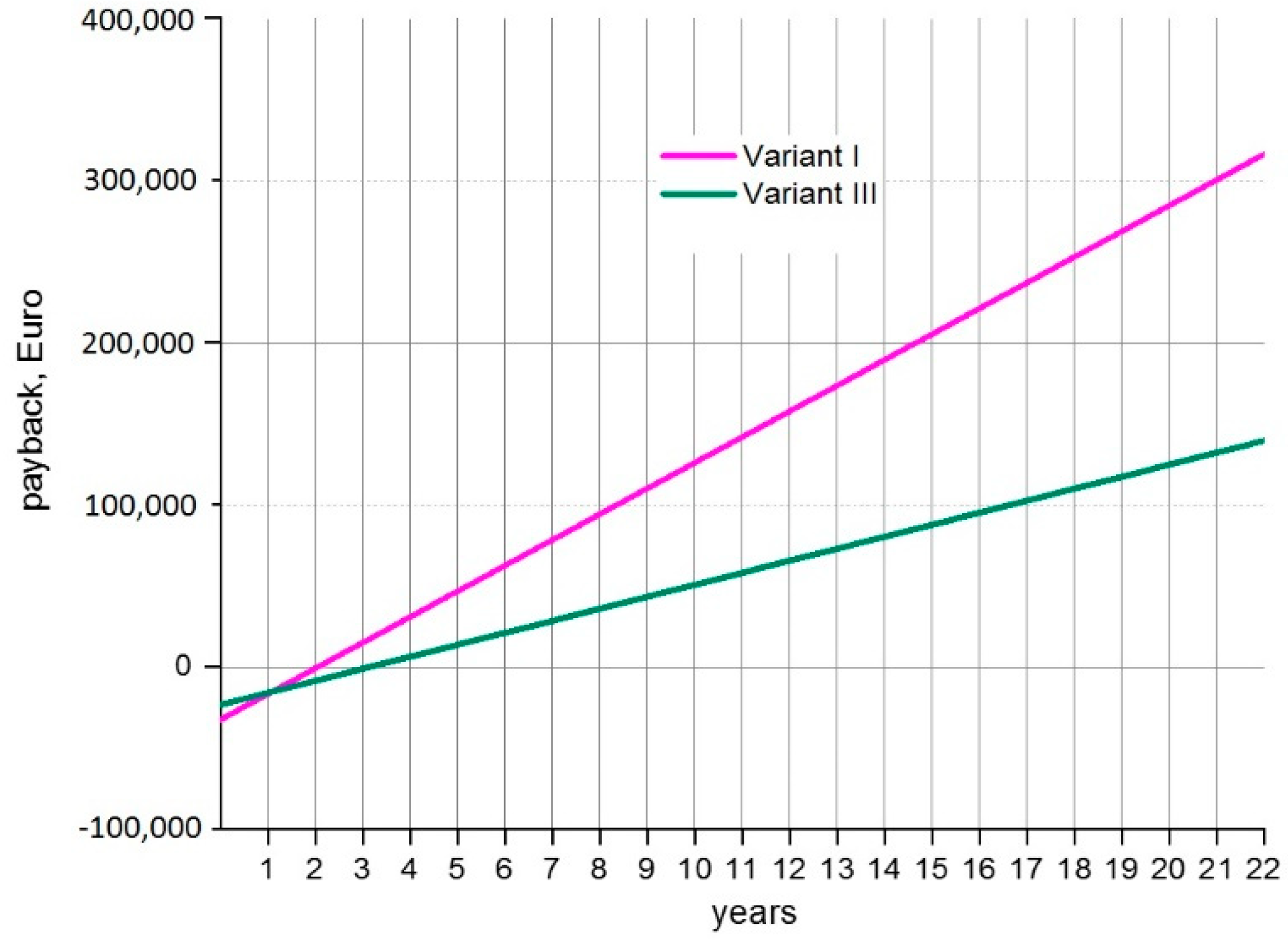
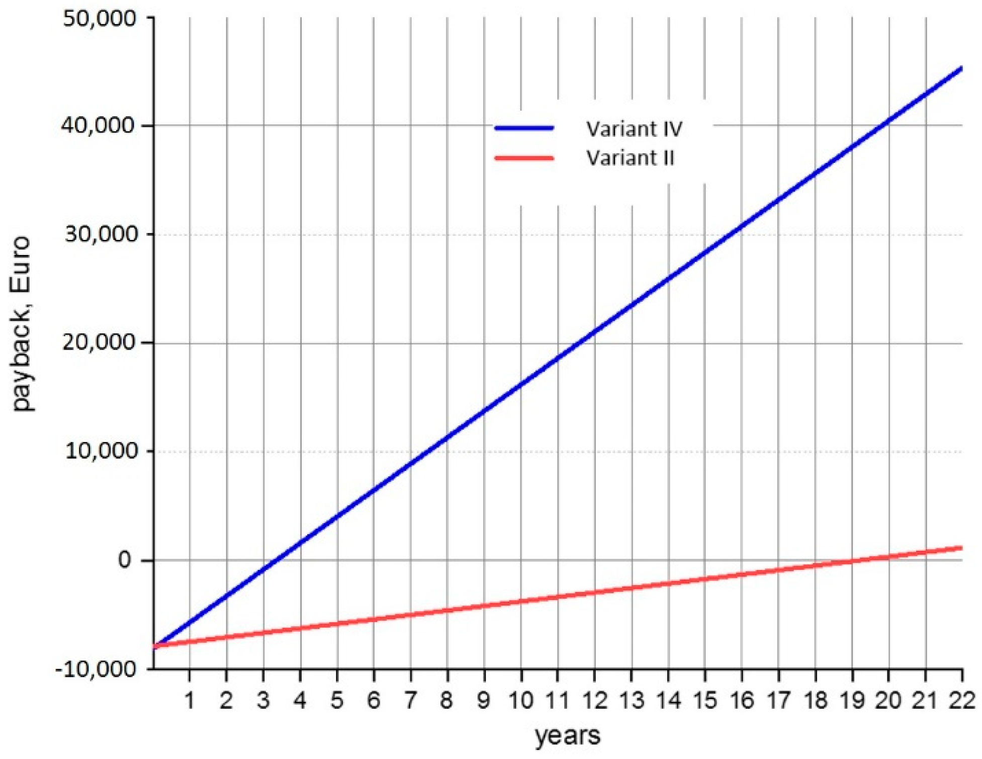
| SPBT (years) | 1.9 | 21 | 3 | 3.4 |
| Variant I | Variant II | Variant III | Variant IV | |
|---|---|---|---|---|
| Annual electricity consumption by the heat pump (kWh/year) | 96,645 | 7889 | 61,143 | 13,149 |
| Energy yield (kWh/year) | 144,255 | 2754 | 42,801 | 25,176 |
| Variant I | Variant II | Variant III | Variant IV | |
| Coal (kg) | 58,640 | 1120 | 17,399 | 10,234 |
| Natural gas (kg) | 10,686 | 204 | 3170 | 1865 |
© 2020 by the authors. Licensee MDPI, Basel, Switzerland. This article is an open access article distributed under the terms and conditions of the Creative Commons Attribution (CC BY) license (http://creativecommons.org/licenses/by/4.0/).
Share and Cite
Słyś, D.; Pochwat, K.; Czarniecki, D. An Analysis of Waste Heat Recovery from Wastewater on Livestock and Agriculture Farms. Resources 2020, 9, 3. https://doi.org/10.3390/resources9010003
Słyś D, Pochwat K, Czarniecki D. An Analysis of Waste Heat Recovery from Wastewater on Livestock and Agriculture Farms. Resources. 2020; 9(1):3. https://doi.org/10.3390/resources9010003
Chicago/Turabian StyleSłyś, Daniel, Kamil Pochwat, and Dorian Czarniecki. 2020. "An Analysis of Waste Heat Recovery from Wastewater on Livestock and Agriculture Farms" Resources 9, no. 1: 3. https://doi.org/10.3390/resources9010003
APA StyleSłyś, D., Pochwat, K., & Czarniecki, D. (2020). An Analysis of Waste Heat Recovery from Wastewater on Livestock and Agriculture Farms. Resources, 9(1), 3. https://doi.org/10.3390/resources9010003