Article

Low-Voltage Ride Through Capability Analysis of a Reduced-Size DFIG Excitation Utilized in Split-Shaft Wind Turbines

Electrical Engineering Technology, School of Engineering Technology, Purdue University, West Lafayette, IN 47906, USA
*
Author to whom correspondence should be addressed.
J. Low Power Electron. Appl. 2025, 15(3), 41; https://doi.org/10.3390/jlpea15030041
Submission received: 19 May 2025 / Revised: 8 July 2025 / Accepted: 18 July 2025 / Published: 21 July 2025

Abstract

Split-shaft wind turbines decouple the turbine’s shaft from the generator’s shaft, enabling several modifications in the drivetrain. One of the significant achievements of a split-shaft drivetrain is the reduction in size of the excitation circuit. The grid-side converter is eliminated, and the rotor-side converter can safely reduce its size to a fraction of a full-size excitation. Therefore, this low-power-rated converter operates at low voltage and handles regular operations well. However, fault conditions may expose weaknesses in the converter and push it to its limits. This paper investigates the effects of the reduced-size rotor-side converter on the voltage ride-through capabilities required from all wind turbines. Four different protection circuits, including the active crowbar, active crowbar along a resistor–inductor circuit (C-RL), series dynamic resistor (SDR), and new-bridge fault current limiter (NBFCL), are employed, and their effects are investigated and compared. Wind turbine controllers are also utilized to reduce the impact of faults on the power electronic converters. One effective method is to store excess energy in the generator’s rotor. The proposed low-voltage ride-through strategies are simulated in MATLAB Simulink (2022b) to validate the results and demonstrate their effectiveness and functionality.

1. Introduction

Employing split-shaft Wind Energy Conversion Systems (WECSs), in which the generator speed and wind rotor speed are decoupled, can mitigate power generation quality issues by optimizing the system’s characteristics, such as the energy storage required. Recently, Hydraulic Transmission Systems (HTSs) have been introduced to Wind Energy Conversion Systems (WECSs) as a mechanism to separate the turbine’s shaft from the generator’s shaft. This technology could be a suitable solution to overcome the challenges of conventional gearbox-based Wind Energy Conversion Systems (WECSs). These challenges include high system downtime in the event of gearbox failure, high installation and maintenance costs, and the need for a more robust tower [1,2,3]. Furthermore, despite the lower efficiency of HTSs, which is about 85–88% [4,5], employing this technology could reduce the capital cost of the WECS and lower the Levelized Cost of Energy (LCOE) and improve the Capacity Factor (CF) of the wind turbine [6,7].
Many studies conducted on different types of HTS have proven that this drivetrain could provide a decoupled transmission system and used this feature to employ a conventional synchronous generator (SG) and eliminate the power converters [8,9,10,11,12,13]. In these studies, two strategies are applied to maintain the SG at synchronous speed with a slight allowed variation and subsequently control the frequency: first, relying on the damping factor of the SG [8,9], and second, inserting an energy buffer between the wind turbine and the SG [10,11,12]. The former strategies can further reduce the efficiency of the synchronous generator due to the ever-changing nature of wind speed, and the latter necessitates the application of other extra subassemblies. Some studies have employed DFIGs instead of SGs to overcome the challenges of utilizing SGs [14,15,16]. The results of [15] show that the size of both power electronic converters, including the Rotor-Side Converter (RSC) and the Grid-Side Converter (GSC), can be reduced by 5%. Ref. [16] proposed a quasi-self-excited hydraulic WECS that employs a DFIG with only 3% of a full-size RSC. Reducing the size of the RSC can further undermine the low-voltage ride-through (LVRT) capability of the DFIG.
Generally, enhancement approaches for the LVRT capability of DFIGs can be divided into three categories: control strategies [17,18,19,20,21,22,23], reactive power injection devices [24,25,26,27], and protection circuits [28,29,30,31,32,33,34,35,36,37,38,39]. Control approaches improve the LVRT capability of the DFIG without additional hardware. In [18], the stator current during the fault is fed back as the rotor current reference to suppress the post-fault rotor current. In [19], a demagnetizing control method is proposed to control rotor current such that it contains both transient and harmful sequence components. A partially demagnetizing control method is proposed in [20] by controlling the rotor flux to track the stator flux with a certain proportion. Virtual resistance control methods and virtual impedance control methods are introduced in [21,22] to increase the system damping by adding another feedback loop on the current control loop. In [23], the RSC is controlled to emulate an inductance for suppressing post-fault rotor current. Although these methods can be effective in moderate voltage dips, they require a high voltage at the RSC to offset the rotor’s electromotive force (EMF) voltage in the event of severe voltage drops. Also, reactive power injection methods, including a dynamic voltage restorer (DVR) [24,25], superconducting fault current limiters [26], and a static synchronous compensator (STATCOM) [27], could be expensive solutions, with the addition of extra components and complexity to the system [40].
On the other hand, numerous studies have been conducted to analyze low-voltage situations in DFIGs that rely on protection circuits, including the crowbar circuit, rotor fault current limiters, and stator fault current limiters. In the simplest form, the crowbar circuit [28] short-circuits the rotor winding of the DFIG to divert the high rotor current from the RSC. However, in this situation, the DFIG behaves like an equivalent squirrel-cage induction generator (SCIG) and draws a substantial magnetizing current during the fault and voltage build-up. In [29], the GSC is controlled to compensate for the consumed reactive power. However, the generator is still absorbing the reactive power. An active crowbar scheme is presented in [30] to prevent losing control of the DFIG during the fault. In [31,32], new vector control methods are proposed to enhance the performance of the crowbar circuit and minimize the length of the crowbar application period.
Additionally, to avoid the disconnection of the RSC during a fault, ref. [33] suggests employing a series dynamic resistor (SDR) along with a crowbar. In [34], the crowbar is replaced by a modified vector control with an R-L circuit connected with the RSC. In addition, some series protection circuits are connected to the stator terminals to limit the fault current. These methods include a series of dynamic braking resistors (SDBR) [35], a new bridge-type fault current limiter (NBFCL) [36], a capacitive bridge-type fault current limiter (CBFCL) [37], and an inductive–resistive-type solid-state fault current limiter (SSFCL-LR) [38]. In [39], the performance of these series methods was compared, and it was demonstrated that the NBFCL outperformed the others.
This paper investigates the LVRT capability of the hydraulic DFIG-based WECS proposed in [15,16], which employed a reduced-size rotor-side converter. Four strategies based on the active crowbar, crowbar with series resistor–inductor (C-RL), SDR, and NBFCL are adopted for the system, and the results are compared.
The rest of the paper is presented as follows: in Section 2, the concept of the hydraulic WECS is elaborated, and the configuration proposed in [16] is explained in Section 3. Then, the challenges of DFIGs in the case of voltage sag are described in Section 4. In Section 5, the proposed LVRT method is presented. Finally, the simulation results of the proposed method under various fault conditions are presented in Section 6.

2. Split-Shaft Drivetrain Model

In the split-shaft transmission system shown in Figure 1, the wind power captured by the turbine rotor is converted to a highly pressurized fluid by a hydraulic pump. Then this power is transferred to the generator through a hydraulic motor at the ground level. In this drivetrain, the high transmission ratio needed can easily be achieved by changing the displacement ratio of the pump and motor. Therefore, a variable-displacement pump or motor (or both) can accomplish the continuously variable transmission (CVT).

2.1. Hydraulic Transmission System Model

The hydraulic pump sustains several torques as it starts to rotate. The governing equations of the hydraulic pump that illustrate the flow and torque balance are as follows [41,42]:
Q h p = D p ω p η v p
J r d ω p d t =   τ r D p P f η t p
The pressurized flow reaching the hydraulic motor makes it start to rotate. The relation of the motor displacement, its angular velocity, and the instantaneous flow rate is as follows:
Q h m = D m ω m η v m
J m d ω m d t = D m P f η t p τ e
The operating pressure dynamic follows the laws of fluid compressibility. Based on the principles of mass conservation and the definition of bulk modulus, the fluid compressibility within the system boundaries can be written as follows:
d P f d t = β f V f   Q h p Q h m

2.2. Energy Conversion Efficiency and Power Flow

Hydraulic machinery utilized in the hydraulic drivetrain has two types of losses, volumetric and torque losses. The volumetric loss of hydraulic pumps and motors reflects the flow leakage of the fluid through the clearance of the mechanical parts of the hydraulic machinery. The volumetric efficiency of the hydraulic pump and motor is obtained as follows:
η v p = 1 C s p A p
η v m = 1 1 + C s m A m
where A p = μ ω p / P f and A m = μ ω m / P f . Moreover, the torque efficiency of the pump and motor is achieved as follows:
η t p = 1 1 + C f p + C v p A p
η t m = 1 C f m C v m   A m
In Equations (8) and (9), C f p and C f m represent the opposing friction torque of the pump and motor, respectively, and are proportional to the displacement and pressure. The viscous damping coefficients C v p and C v m represent the viscous torque required to shear fluid in the small clearance of hydraulic machinery.
The power flow diagram of the hydraulic drivetrain is presented in Figure 2. The turbine captures the power P p , which is received at the hydraulic pump. The torque loss of the pump causes the pump’s output to become D p ω p P f . A portion of this power becomes the volumetric loss ( 1 η v p ) D p ω p P f . The remaining power is the power of a pressurized fluid that is equal to Q P f , which is transferred through pipes to the hydraulic motor. Similarly, the volumetric efficiency of the motor cuts the pressurized power of the fluid to D m ω m P f . The overall volumetric efficiency of the drivetrain equals the product of volumetric pump and motor efficiencies, i.e., η v = η v m η v p . Finally, the torque efficiency of the hydraulic motor reduces the term D m ω m P f to the output power P m .

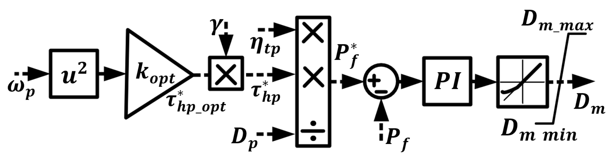
2.3. Optimal Hydraulic Motor Displacement Control

The configuration has a fixed-displacement pump in the nacelle, driven by the turbine shaft, and a variable-displacement hydraulic motor at ground level. The optimal power production of a wind turbine is achieved. The tip speed ratio must be optimum ( λ o ) to obtain the maximum harvested power from the wind. The optimum pressure can be followed by controlling the displacement of the hydraulic motor to obtain the maximum power coefficient ( C p m a x ). The optimal pressure is obtained as follows:
P f o = 1 2 λ o 3   D p η t p ρ π R 5 C p m a x ω p 2

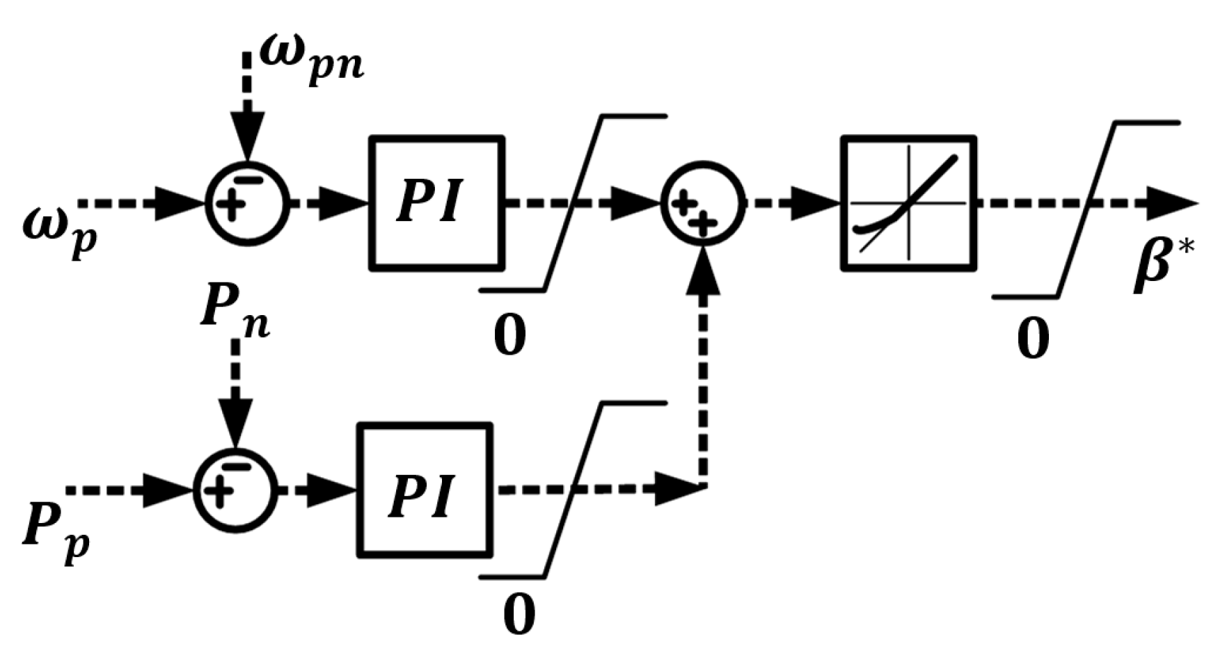
2.4. Optimal Pump Displacement Control (OPDC)

The configuration has a variable-displacement pump in the nacelle, driven by the turbine shaft, and a fixed-displacement hydraulic motor at ground level. For different wind speeds, the pump speed is controlled through the pump displacement to obtain the maximum power coefficient ( C p m a x ). The optimum pump displacement is obtained as follows [14]:
D p o = 1 2 λ o 3   P f η t p ρ π R 5 C p m a x ω p 2
In this WECS, the wind turbine angular velocity and the generator speed are decoupled by a hydraulic power transmission system.

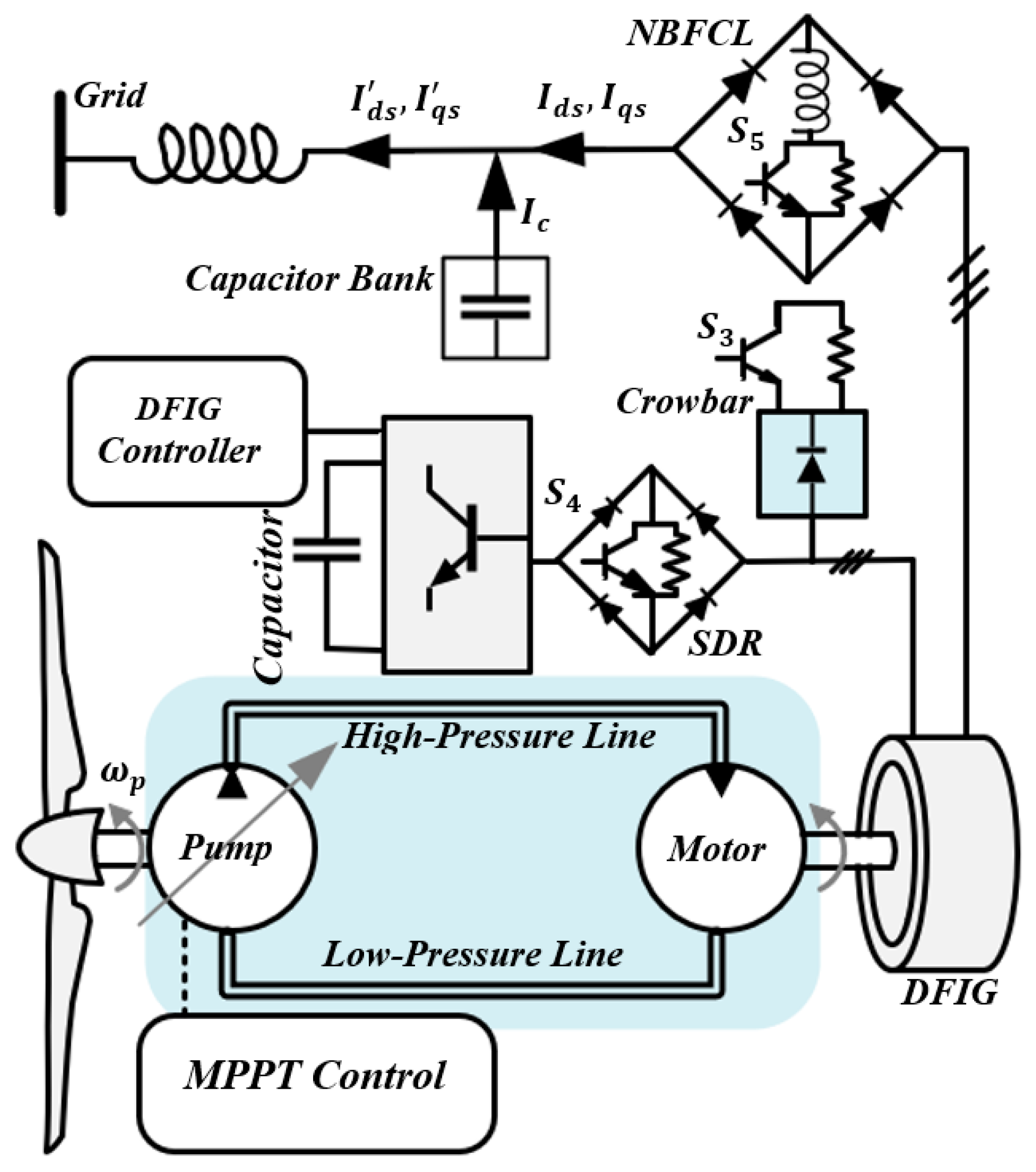
3. Quasi-Self-Excited Hydraulic WECS

The configuration shown in Figure 1 employs the extra degree of freedom that HTSs can provide to control the speed of the generator regardless of the wind speed and turbine shaft speed. Therefore, the power passing through the generator rotor windings can control the generator speed only to provide the RSC and rotor windings loss. Since the power loss of the rotor windings and converter is only a small portion of the nominal power, the slip of the DFIG would be small, as follows (performance of this configuration is explained in detail in [16]):
s t = P l c + P l r P a s
where s t is the target slip in which the power passing through the DFIG rotor provides the converter and rotor winding losses. P a s is the power of the stator airgap, and P l c and P l r are the converter and rotor losses, respectively. In this configuration, the power rating of the converter, which is only a RSC, reduces noticeably by 97% to only 3% of the full size. By considering the dynamics of the stator and rotor, the rotor and stator voltage equations in the stator flux-oriented frame are as follows [34]:
V q r V d r = R r 0 0 R r   I q r I d r + d / d t s ω s s ω s d / d t   λ q r λ d r
V q s V d s = R s 0 0 R s   I q s I d s + d / d t ω s ω s d / d t   λ q s λ d s
where variables V , I , λ , s , ω s are voltage, current, flux, slip, and synchronous speed, respectively. Subscripts q r , q s ,   d r , d s are the quadrature components of rotor and stator variables and direct components of the rotor and stator variables, respectively. The flux equations of the DFIG are calculated as follows:
λ q s λ d s = L s 0 0 L s   I q s I d s + L m 0 0 L m   I q r I d r
λ q r λ d r = L m 0 0 L m   I q s I d s + L r 0 0 L r   I q r I d r
By eliminating the stator current from the rotor flux Equation (16) using (15) and replacing the flux equations of the rotor in (13), the rotor voltage equations can be rewritten as follows:
V q r V d r = R r + σ L r d / d t s ω s σ L r s ω s σ L r R r + σ L r d / d t   I q r I d r + L m L s V q s ( 1 s ) ω s λ d s V d s + ( 1 s ) ω s λ q s
where the leakage factor is equal to σ = 1 L m 2 / ( L r L s ) . Considering the Equation (17) and adding the decoupled terms, the vector control shown in Figure 3 is obtained. The controller utilizes five switches to activate fault-suppressing technologies for comparison.

4. LVRT Challenges for DFIG

The challenges that WECSs experience in fault and low-voltage cases are twofold: first, those related to the requirements dictated by grid codes [43,44,45,46]; second, challenges associated with the protection of the system [47,48].

4.1. Grid Code Requirements

According to recent grid codes [43,44,45,46], wind turbines should remain connected to the power grid during voltage dips and withstand a specific voltage dip for a specified time before tripping off. The reason for this is that an unnecessary disconnection might degrade voltage restoration after faults and might have severe effects on the transient and steady-state stability of power system operation [49]. Moreover, some transmission system operators expect power generation units to inject reactive power into the grid during a fault to enhance voltage recovery. The expected reactive power is dependent on the amount of voltage dip and can be different for different transmission operators [45].

4.2. Protection Measures

On the other hand, a DFIG has the disadvantage of high vulnerability to grid disturbances, especially low-voltage and short-circuit cases [47,48]. Due to the direct integration of the DFIG stator into the power grid, when a short circuit or voltage sag happens at the grid side, large currents are drawn to demagnetize the machine. These transient demagnetizing currents, which last several cycles, induce a large voltage in the rotor windings. As a result, high rotor currents are generated in the rotor windings, which in turn flow towards the back-to-back power converters and may cause damage to the RSC. It is worth mentioning that the thermal time constant of the DFIG itself is sufficiently large, allowing the DFIG to handle the fault transient current.
Moreover, the wind power harvested by the wind turbine cannot be transferred into the power grid during faults due to the current restraints of the generator and power converter. This unbalanced power can increase generator speed, leading to a loss of generator control. After the fault is cleared, the converter cannot provide the necessary voltage to control the generator. Additionally, this increase could lead to a rise in rotor power and an increase in the DC-link voltage. This overvoltage could exceed the rating of the converter and the DC-link capacitor and damage them [47,48].

5. Proposed LVRT for Hydraulic Wind Turbine

Since the size of the converter in the split-shaft hydraulic wind turbine is significantly reduced, and the GSC is eliminated, meeting the required LVRT capability may be challenging. The DFIG speed should be controlled to remain close to synchronous speed and prevent overvoltage of the DC link during the fault. To this end, the hydraulic machinery displacement is controlled such that the amount of power transferred to the DFIG is decreased. Accordingly, only a portion of wind power is captured ( γ ) . The energy is transferred to the generator, and the surplus power is transferred to the rotor of the wind turbine, increasing its kinetic energy. This power can be returned to the grid after the fault is cleared. This control strategy is shown in Figure 4 and Figure 5. If the speed of the turbine rotor exceeds the nominal value, the pitch angle controller shown in Figure 6 is activated to limit the turbine speed.

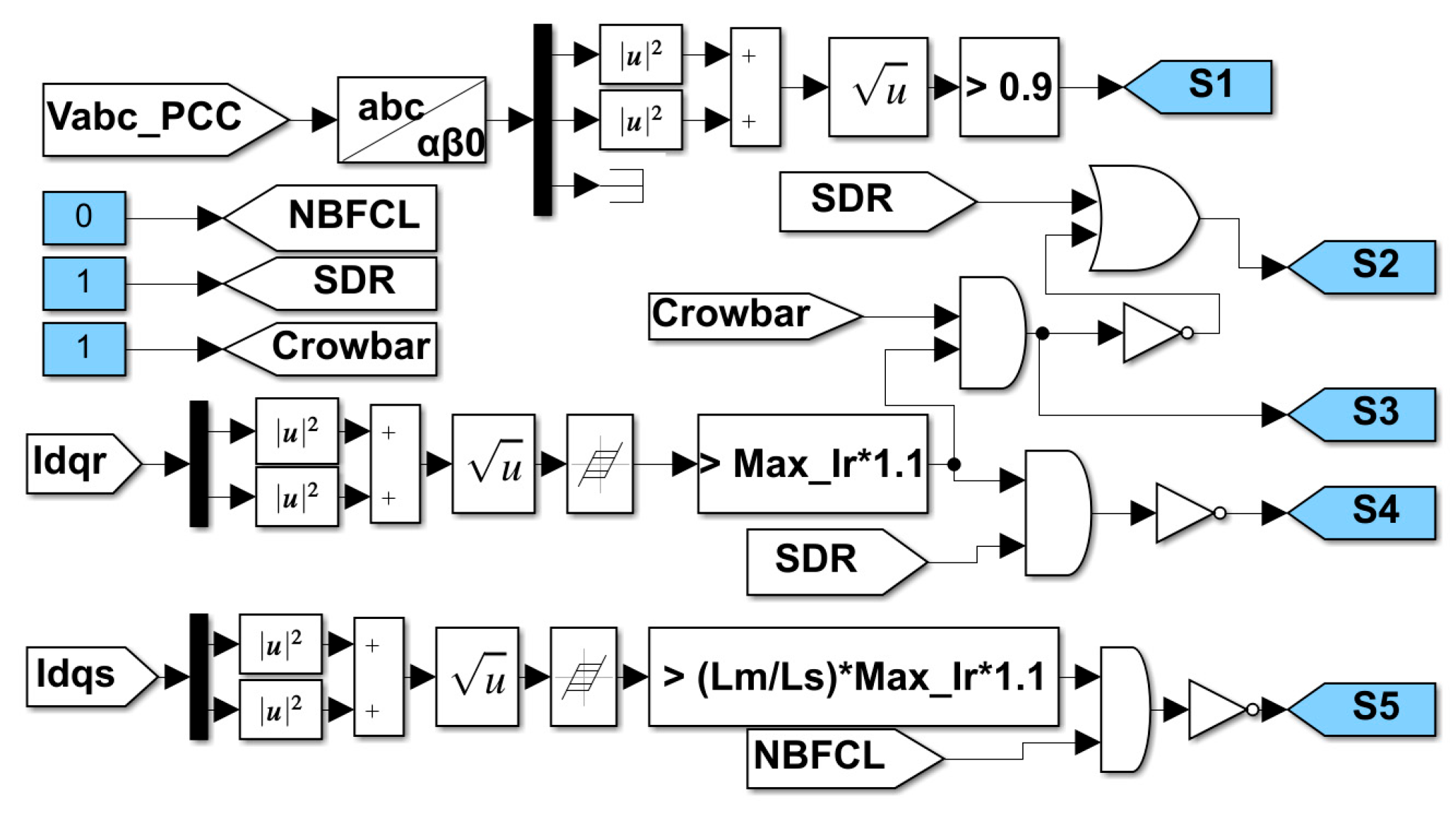
5.1. Overcurrent and Overvoltage Protection

The DFIG controller is illustrated in Figure 3 for both regular and fault conditions. The blue shaded blocks (labeled normal) are for the typical process, and the orange shaded blocks (labeled fault) are activated during faults. In this paper, the performance of crowbar, C-RL, SDR, and NBFCL is explored individually. These protection circuits are shown in Figure 1. The logic for switching S1–S5 switches, shown in Figure 1 and Figure 3, is demonstrated in Figure 7. To better understand this logic diagram, Table 1 displays the state of each switch in various protection circuits. In general, in a fault situation, the position of S1 changes from 1 to 0 for all protection strategies. However, S2 is only used when the active crowbar (C) is activated to deactivate the RSC. S3 is activated whenever the crowbar or C-RL is utilized, and the current exceeds the threshold current during the fault. S5 and S6 are activated during the fault when SDR and NBFCL are employed, and the current exceeds the threshold current, respectively. All proportional–integral (PI) controllers in the blue shaded block (regular operation) during the fault are forced to restart with a reference equal to the last measured value to achieve a soft restoration of the controller [28].
(1)
Active Crowbar (C)
This protection circuit is activated by turning on S3, shown in Figure 1. During the fault, the circuit is activated whenever the rotor current exceeds the converter current rating. This switch is deactivated when the current is less than the converter’s rated current. Furthermore, the DFIG also draws a sizable reactive power for magnetizing the machine after fault clearance, during which the rotor current can increase again. The active crowbar strategy is applied to protect the RSC after fault clearance. The amount of the dynamic crowbar resistor is defined based on [29]. Furthermore, when the crowbar is activated, S3 is deactivated, switching off the PWM signal.
The direct and quadratic components of the current have limitations under normal and fault conditions. During regular operation, the direct component of the rotor current is limited by I d r * I r n 2 I q r * 2 to ensure active power delivery to the grid, which is defined by the I q r * . However, under fault conditions, a minimum amount of reactive current is required to maintain the voltage, and the remaining current capacity of the converter can be utilized for active power. Therefore, under fault, the quadrature component of the rotor current is limited to I q r * < I r n 2 I d r * 2 .
(2)
Crowbar and RL (C-RL)
In this protection approach, both the crowbar and the SDR are activated during the fault. The RSC remains connected to the rotor winding during the fault, and there is no need to turn off the RSC PWM. The value of the resistances is chosen such that the DC-link voltage during a fault does not experience an overvoltage, based on [33].
(3)
SDR
The SDR is connected in series with the RSC. In normal conditions, the IGBT (S4) is on. During a fault, the switch turns off whenever the rotor current exceeds a predefined threshold. The series inductor prevents a sudden change in rotor current. A simulation defines the optimal resistor value.
(4)
NBFCL
NBFCL is connected in series with the stator. When the stator current exceeds the predefined threshold, the IGBT (S5) is turned off.
Two crucial parameters, I d r * and P f a u l t * , should be accurately defined because the first determines the amount of reactive current injected into the grid. The second defines the amount of active power injected into the grid during the fault. It is better to inject as much active power as the RSC allows without overloading the converter during the fault.

5.2. Reactive Current Reference Calculations

To calculate I d r * , the direct component of the stator, I d s * (these currents are shown in Figure 1), should be calculated first. According to [45], this amount can be obtained based on the amount of voltage dip, as follows:
I d s * = 0 Δ V > 0.1 2 Δ V + 0.1 I s n 0.6 < Δ V < 0.1 I s n Δ V < 0.6
where Δ V = ( V s V s n ) / V s n , and V s n is the nominal stator voltage. By using (15), and considering the equations of the capacitor bank in d q frame, the d q components of the current that are injected into the PCC are obtained as follows:
I q s I d s = 1 L s ω s 2 C 0 0 1 L s ω s 2 C λ q s λ d s L m L s 0 0 L m L s I q r I d r
where I q s , I d s are direct and quadrature components of the current injected into the PCC. Then, according to Figure 1, the reactive current injected into the grid is as follows:
Q s = 3 2 ω s C 1 L s ω s V d s 2 + V q s 2 + L m L s ( V q s I d r V d s I q r ) = Q c Q m + Q s
where Q c = 3 2 ω s C V d s 2 + V q s 2 and Q m = 3 2 V d s 2 + V q s 2 / ( L s ω s ) are the capacitor bank’s reactive power and the generator’s magnetizing reactive power, respectively. It is assumed that the amount of reactive power of the capacitor bank at the stator is designed such that it cancels out the magnetizing current of the generator:
Q c = Q m   C = 1 ω s 2 L s  
Therefore, the relationship between d q components of the rotor current and current at the PCC is obtained as follows:
I q s I d s = L m / L s 0 0 L m / L s I q r I d r
The size of the capacitor (22) enables the DFIG complex to inject and absorb a similar amount of reactive power, as shown in Figure 8.
Using (18), (21) and (22,) the amount of I d r * can be obtained as follows:
I d r * = L s L m 0 Δ V > 0.1 2 Δ V + 0.1 I s n 0.6 < Δ V < 0.1 I s n Δ V < 0.6

5.3. Active Power Reference Calculation

To calculate the reference of the active power during the fault, first, P f a u l t * , the remaining current capacity of the RSC, should be calculated. The maximum quadratic component of rotor current, I q r _ m a x , can be obtained as follows:
I q r _ m a x = I r n 2 I d r * 2
Therefore, using (23) and (24), the maximum active power that can be transformed to the grid during the fault is obtained as follows:
P s _ m a x = 3 2 V q s I q s = L m L s V s   I r n 2 I d r * 2  
From the stability point of view and to prevent DC-link overvoltage and acceleration of the DFIG, the output power of the hydraulic machinery needs to be adjusted to the amount that can be transferred to the grid. Accordingly, γ in Figure 4 and Figure 5 can be calculated as follows:
γ = min 1 , P s _ m a x η t K o p t ω p 3
Consequently, the reference power during faults can be adjusted as follows:
P f a u l t * = ω m D m P f η t m

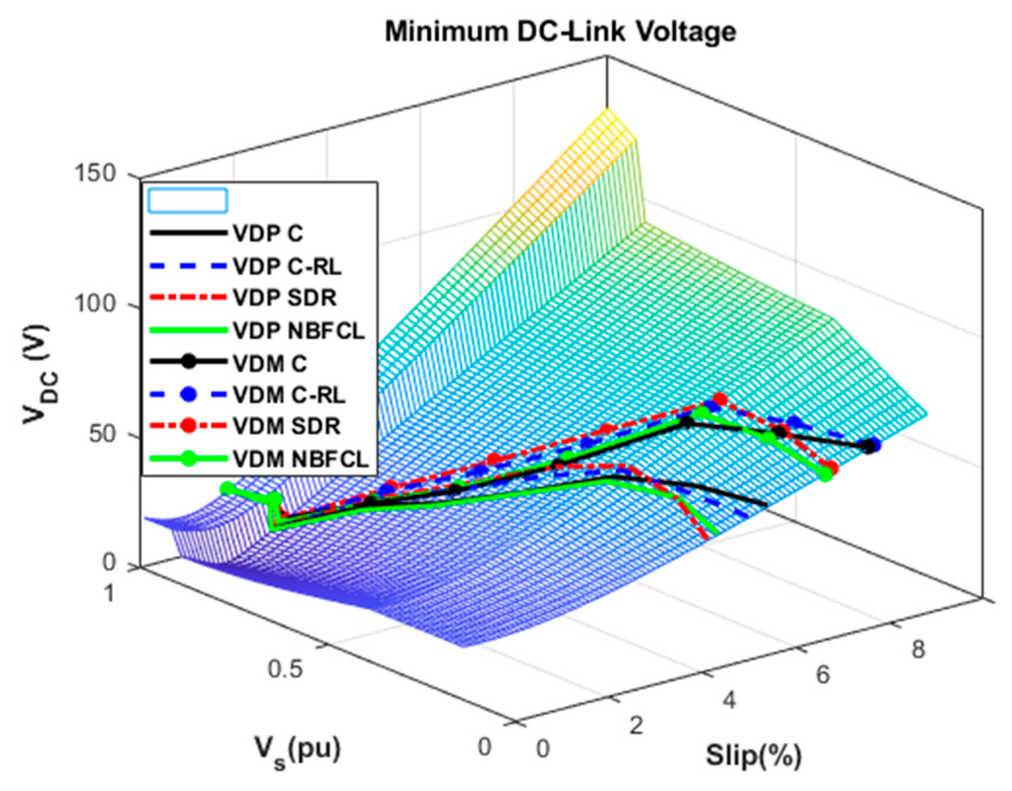
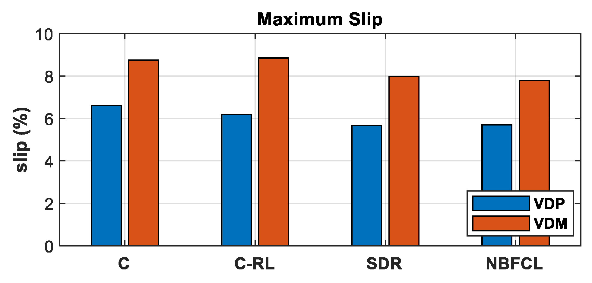
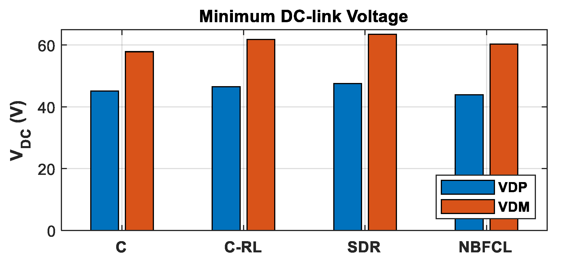
6. Design of Experiment and Simulation Results

Split-shaft hydraulic drivetrains can utilize variable displacement pumps at the turbine side or variable displacement motors at the generator side. Both configurations are simulated under a three-phase fault to analyze the ability of the reduced-size excitation system. The objective is to meet the US grid LVRT performance requirements. Accordingly, when the voltage at the PCC drops to 15%, the generator and its supporting components should continue operation for 0.625 s. A fault was scheduled at t = 4   s , which lasted for 0.625 s. The wind speed was considered 11 m/s (nominal power) and remained constant for low-voltage analysis. Before the fault, the amount of the reactive power injected into the grid was zero, and the rest of the system was at steady-state values.

6.1. Variable-Displacement Pump (VDP) Configuration

First, to determine the optimal value for the SDR and NBFCL resistors, the maximum current of the converter was obtained by simulation for different resistor values at different voltage phases, as shown in Figure 9. With a 0.6 per unit ( p u . ) resistor, both curves in Figure 9 reached an optimal value.
Figure 10a shows the PCC voltage profile for all four cases of LVRT protection techniques. The PCC voltage shows a drop to 15% at the time 4   s . The figure demonstrates a rapid voltage recovery to its nominal value without requiring generator disconnection. With the NBFCL protection circuit, the stator voltage dropped with a delay due to the voltage drop across the resistor at the stator side. The PCC’s reactive and active current components are shown in Figure 10b,c, respectively. During the fault, the amount of active current decreased, and one per unit (pu) of reactive current was injected into the grid to maintain the voltage at the point of common coupling (PCC). The figures show that the transient fault current was damped using the NBFCL technique, whereas other methods remained oscillatory for approximately 200 ms. When the crowbar protection strategy was employed, the peak of the fault current reached its maximum. However, the current crest decreased in the partially controlled C-RL. This peak was limited further in SDR because of its fully controlled approach. However, the transient of the current could not be eliminated due to the small size of the RSC.
The active power delivered to the PCC during a fault for four protection circuits is shown in Figure 11a. At the beginning of the fault with the NBFCL protection, the amount of active power injected into the power grid was approximately one percent (1 pu). The main portion of this power was transferred to the resistor in the NBFCL configuration. The protection circuits were reactivated after the fault was cleared. With the crowbar configuration, the rotor excitation circuit becomes short-circuited, and the machine behaves as a Synchronous Condenser–Induction Generator (SCIG). Therefore, there is no control applicable to the rotor excitation. For this reason, it was observed that the active power remained close to 1 p.u. (Figure 11a) but drew a large magnetizing reactive power (Figure 11b) after the clearance of the fault. In the C-RL configuration, the magnetizing reactive power decreased due to the partially controlled approach, as shown in Figure 11b. This magnetizing reactive power was reduced further to zero in the SDR protection circuit. In general, the performance of the C-RL was a trade-off between the performance of the crowbar and SDR configurations.
The turbine speed began to increase at the onset of the fault and reached a 5% overshoot, as illustrated in Figure 12a. Then, the turbine speed began to decrease with a delay after the fault was cleared. With the appearance of overshoot, pitch angle control was activated to limit the speed, as shown in Figure 12b. As a result of displacement control and pitch angle control, the pressure of the fluid decreases during the fault (Figure 13a) to limit the power at the hydraulic motor head. The fluid pressure begins to increase with a slight delay after the fault is cleared. When the pressure is recovered, the turbine’s speed starts to decrease. The amount of γ factor was obtained for all configurations, as shown in Figure 13b. Due to the voltage at the terminal of the DFIG, γ for NBFCL was slightly higher at the beginning of the fault. After the clearance of the fault, γ became one, and the displacement of the pump was controlled accordingly (Figure 13c).
The DC-link voltage for all configurations is illustrated in Figure 14a. The variation observed at the DC-link voltage was the least when the SDR configuration was utilized. In general, these variations were within ±   7 % for all configurations. The generator speeds are shown in Figure 14b for all protection circuits. As the figure shows, the fluctuation of the generator speed remained close to the synchronous speed. The NBFCL and SDR showed a lower generator speed swing. Figure 15 demonstrates the current of the rotor and converter of a single phase in the three-phase system. During faults, the rotor current reached about 3.5 pu when the crowbar was used. The same current was reduced to 2.5 pu in the C-RL configuration. However, the converter was protected against overcurrent by a bypass route provided by the crowbar. The maximum current of the converter for all configurations reached 1.4 pu, as shown in Figure 15b.
It can be observed that all configurations protected the system and provided the LVRT requirements. However, the SDR and NBFCL outperform the other methods. The SDR configuration can better manage the reactive power of the generator after fault clearance, and the NBFCL improves the system’s oscillatory performance during the fault.

6.2. Variable-Displacement Motor (VDM) Configuration

The variable-displacement motor directly controls the generator speed and indirectly affects the turbine’s rotational speed. Hence, the performance of the protection techniques selected for LVRT is different. The value of the fault-current-suppressing resistor needs to be optimized accordingly. Figure 16 shows the variation of the fault current with respect to the fault current resistor values under the SDR and NBFCL current-limiting techniques, which yielded similar results to those in Figure 9. With the SDR and NBFCL techniques, the converter current decreased sharply as the resistor value increased up to 0.6 p.u. However, the rotor current did not change significantly for the resistor above 0.6 p.u.
In the case of the variable-displacement motor, the voltage of the PCC dropped to 15% at the time 4 s, as shown in Figure 17a. The voltage of the stator for all configurations is illustrated in Figure 17a. The stator voltage was restored to its nominal value immediately after the fault clearance. Similar to the VDP (shown in Figure 10a), the stator voltage decreased with a delay in the NBFCL protection (Figure 17a). The reactive currents at the PCC shown in Figure 17b reached one p.u. during the fault. Due to the limited capacity of the converter, the active current injected into the grid during the fault decreased, as shown in Figure 17c. The active and reactive powers are illustrated in Figure 18. The performance of all configurations was similar to that of the variable-displacement-pump drivetrain.
Immediately after the fault, the turbine’s speed rose by a 4% overshoot. This is illustrated in Figure 19a. The speed started to decrease as the fault cleared. Similarly, as the speed exceeded the nominal value, the pitch angle control was activated, limiting the speed, as shown in Figure 19b. As a result of the displacement control and pitch angle control, the pressure of the fluid decreased during the fault (Figure 20a) to limit the power at the hydraulic motor head. The effect on the γ is shown for all configurations in Figure 20b. The control effort, as the motor displacement for all LVRT control techniques, is shown in Figure 20c.
The DC-link voltage for all configurations is shown in Figure 21a. A significant DC-link voltage fluctuation was observed in the variable-displacement-motor configurations compared with the variable-displacement-pump configurations, as previously shown in Figure 14a. These variations remained within 8%. However, minor variations were observed in the SDR configuration. The generator speed is shown in Figure 21b.
Similarly, around 9% speed variation was observed in the variable-displacement-pump configurations. The generator speed variation for the NBFCL protection circuit was less than that of other protection techniques. Figure 22 demonstrates the current of the rotor and converter for one phase of the three-phase system. The current of the converter for all configurations was limited to 1.4 p.u.

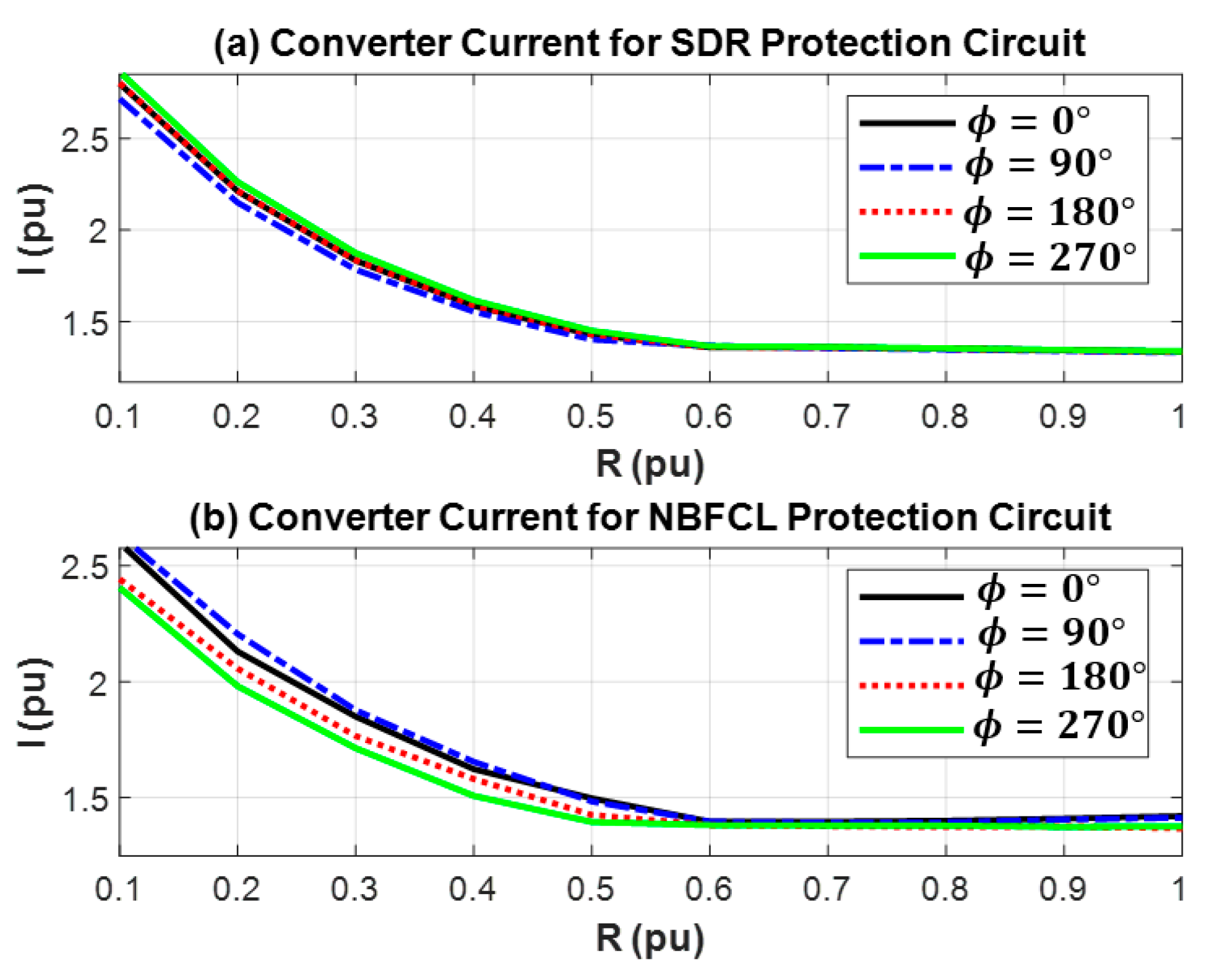
7. Converter Size Determination

The size of the converter depends on the minimum DC link required to control the system and the maximum current of the RSC during the fault. The minimum DC-link voltage is correlated to the maximum slip of the DFIG during its operation. Herein, the d q frame is chosen such that all stator flux is aligned with the d axis. Therefore, λ q s = 0 in steady state. Neglecting the stator resistor ( R s = 0 ), the direct component of the stator voltage will be zero ( V d s = 0 ), and λ d s = V q s / ω s , according to (14). By replacing this simplification in (17), the rotor voltage and minimum DC-link voltage can be achieved as follows:
V q r V d r = R r s ω s σ L r s ω s σ L r R r   I q r I d r + L m L s s V q s 0
V D C 2 V q r 2 + V d r 2
Figure 23 illustrates the minimum DC-link voltage for various DFIG slip and stator voltages. This figure consists of three surfaces related to the different voltage levels (23). During faults, the current of the rotor can be achieved based on (23) and (24), and the minimum DC-link voltage can be calculated. The maximum DFIG slip can be obtained by simulating the system at various fault voltages. However, in normal operation, the maximum slip of the generator is less than 2% [16], and the DC-link voltage calculated is less than the value required during the fault. The smaller the maximum slip of the DFIG, the smaller the DC-link voltage required to ride through the fault and ensure the grid code. The boundary of the minimum DC-link voltage for different configurations is shown in Figure 23.
Based on the boundaries shown in Figure 23, the maximum slip and minimum DC-link voltage for all operating points and fault conditions are shown in Figure 24 and Figure 25. It is shown that the DFIG slip reaches a higher point for the VDM configuration than the VDP one. Thus, the minimum DC-link voltage is achieved at a higher value for the VDM. Based on these results, the RSC size for different protection circuits is obtained and shown in Figure 26. In general, the converter size is less than 6% and 8% for the VDP and VDM configurations, respectively. Therefore, the VDP configuration is a better choice in terms of the size of the converter.
Among drivetrain configurations, the VDP drivetrain performs better than the VDM one. At the beginning of the fault, decreasing the pump displacement reduces hydraulic power while simultaneously increasing wind turbine speed. However, increasing the motor’s displacement in the VDM at the beginning of the fault increases the output power, leading to a decrease in pressure and eventually an increase in wind turbine speed. This is the primary reason for the more significant slip variation in the VDM. Among protection circuits, the NBFCL configuration is a suitable option for attenuating system oscillation during a fault. The SDR is an acceptable option for controlling reactive power after fault clearance. All configurations need an RSC of a small size.

8. Conclusions

Low-voltage ride-through capabilities of split-shaft wind turbine drivetrains have been analyzed. A control technique was introduced to divert the energy from the generator to the wind turbine during the fault. This reduced the fault current fed by the generator. As a requirement, the DFIG was controlled to operate close to synchronous speed. The performance of four protection circuits, including a crowbar, C-RL, SDR, and NBFCL, was evaluated in two split-shaft drivetrain configurations, VDM and VDP. It was observed that the protection circuit did not significantly change the size of the converter. This allowed employment of an RSC with 6% and 8% for VDP and VDM configurations, respectively.
The system managed the fault transients under NBFCL better, while also helping to reduce the stator and rotor-side transients. However, C-RL and SDR protection circuits managed the active and reactive power generation controls better. The protection circuits prevented the overcurrent and overvoltage of the RSC and DC-link capacitor. Therefore, the proposed system configuration successfully provided the required fault ride-through voltage profile with a reduced-size power converter.

Author Contributions

Conceptualization, validation, R.A. and A.I. Original draft, R.A.; Writing, Editing, Project Administration A.I. All authors have read and agreed to the published version of the manuscript.

Funding

This research received no external funding.

Data Availability Statement

The original contributions presented in this study are included in the article. Further inquiries can be directed to the corresponding author.

Conflicts of Interest

The authors declare no conflict of interest.

Nomenclature

Greek symbols:
β r e f Pitch angle reference
β f Bulk modulus of the fluid
η t p ,   η t m Torque efficiency of hydraulic pump and motor
η v p ,   η v m Volumetric efficiency of hydraulic pump and motor
η v Volumetric efficiency of the hydraulic drivetrain
λ d s ,   λ q s Direct and quadrature components of stator flux
λ o Optimal tip speed ratio
μ Dynamic viscosity of the fluid
ρ Air density
τ e ,   τ r Electrical and wind turbine torques
τ h p Torque of hydraulic pump
τ b p ,   τ b m Breakaway torque of hydraulic pump and motor
ω p ,   ω m Pump and motor angular velocities
ω s Synchronous angular velocity of the DFIG
Latin symbols:
C p m a x Maximum power capacity of the wind turbine
C f p ,   C f m Coulomb friction coefficient of the hydraulic pump and motor
C s p ,   C s m Slippage coefficient of the hydraulic pump and motor
C v p ,   C v m   Viscous drag coefficient of the hydraulic pump and motor
D p ,   D m Hydraulic pump and motor displacements
D p o Optimal pump displacement
I d r ,   I q r Direct and quadrature components of the rotor current
I d s ,   I q s Direct and quadrature components of the stator current
I r n Nominal rotor current
J r Wind rotor–hydraulic pump inertia
J m Generator–hydraulic motor inertia
L s ,   L r ,   L m Stator, rotor, and magnetizing inductances
P f Pressure of the fluid
p Pole number of the DFIG
P l c ,   P l r Converter and rotor losses
P a Aerodynamic power of the wind turbine
P a s Air gap power of stator
P h m Mechanical power of the hydraulic motor
P e Electrical power of the DFIG
Q h p ,   Q h m Flow of hydraulic pump and motor
Q s ,   Q m Stator and magnetizing reactive power of the DFIG
Q c Reactive power of the capacitor bank
R Radius of the rotor of the wind turbine
R s ,   R r Stator and rotor resistance
s t Target DFIG slip
s DFIG slip
V f Volume of the fluid
V d r ,   V q r Direct and quadrature components of the rotor voltage
V d s ,   V q s Direct and quadrature components of the stator voltage
v Wind velocity

References

  1. Artigao, E.; Martín-Martínez, S.; Honrubia-Escribano, A.; Gómez-Lázaro, E. Wind turbine reliability: A comprehensive review towards effective condition monitoring development. Appl. Energy 2018, 228, 1569–1583. [Google Scholar] [CrossRef]
  2. Tazi, N.; Châtelet, E.; Bouzidi, Y. Using a hybrid cost-FMEA analysis for wind turbine reliability analysis. Energies 2017, 10, 276. [Google Scholar] [CrossRef]
  3. Taherian-Fard, E.; Sahebi, R.; Niknam, T.; Izadian, A.; Shasadeghi, M. Wind Turbine Drivetrain Technologies. IEEE Trans. Ind. Appl. 2020, 56, 1729–1741. [Google Scholar] [CrossRef]
  4. Henderson, G.; Gevorgian, V.; Yan, W.; Flynn, D.; Mendieta, W.; Alam, S.M.S. Type 5 wind turbine technologies: Three main candidates compared. In Proceedings of the 23rd Wind & Solar Integration Workshop (WIW 2024), Helsinki, Finland, 8–11 October 2024. [Google Scholar]
  5. Deldar, M.; Izadian, A.; Anwar, S. A decentralized multivariable controller for hydrostatic wind turbine drivetrain. Asian J. Control 2019, 22, 1038–1051. [Google Scholar] [CrossRef]
  6. Deldar, M.; Izadian, A.; Anwar, S. Reconfiguration of a wind turbine with hydrostatic drivetrain to improve annual energy production. In Proceedings of the 2015 IEEE Energy Conversion Congress and Exposition (ECCE), Montreal, QC, Canada, 20–24 September 2015; pp. 6660–6666. [Google Scholar]
  7. Jarquin Laguna, A. Steady-State Performance of the Delft Offshore Turbine. Master’s Thesis, Delft University of Technology, Delft, The Netherlands, 2010. [Google Scholar]
  8. Rajabhandharaks, D.; Hsu, P. Optimal aerodynamic energy capture strategies for hydrostatic transmission wind turbine. In Proceedings of the 2014 IEEE Conference on Technologies for Sustainability (SusTech), Portland, OR, USA, 24–26 July 2014; pp. 140–147. [Google Scholar]
  9. Do, H.T.; Dang, T.D.; Truong, H.V.A.; Ahn, K.K. Maximum Power Point Tracking and Output Power Control on Pressure Coupling Wind Energy Conversion System. IEEE Trans. Ind. Electron. 2018, 65, 1316–1324. [Google Scholar] [CrossRef]
  10. Chen, M.; Santos, S.M.; Izadian, A. Torque-Assisting compressed air energy storage hydraulic wind drivetrains. In Proceedings of the 2016 IEEE Power and Energy Conference at Illinois (PECI), Urbana, IL, USA, 19–20 February 2016; pp. 1–5. [Google Scholar]
  11. Wei, L.; Liu, Z.; Zhao, Y.; Wang, G.; Tao, Y. Modeling and Control of a 600 kW Closed Hydraulic Wind Turbine with an Energy Storage System. Appl. Sci. 2018, 8, 1314. [Google Scholar] [CrossRef]
  12. Liu, Z.; Tao, Y.; Wei, L.; Zhan, P.; Yue, D. Analysis of Dynamic Characteristics of a 600 kW Storage Type Wind Turbine with Hybrid Hydraulic Transmission. Processes 2019, 7, 397. [Google Scholar] [CrossRef]
  13. Ai, C.; Zhou, G.; Gao, W.; Guo, J.; Jie, G.; Han, Z.; Kong, X. Research on Quasi-Synchronous Grid-Connected Control of Hydraulic Wind Turbine. IEEE Access 2020, 8, 126092–126108. [Google Scholar] [CrossRef]
  14. Akbari, R.; Izadian, A.; Weissbach, R. An Approach in Torque Control of Hydraulic Wind Turbine Powertrains. In Proceedings of the 2019 IEEE Energy Conversion Congress and Exposition (ECCE), Baltimore, MD, USA, 29 September–3 October 2019; pp. 979–982. [Google Scholar]
  15. Akbari, R.; Izadian, A. Reduced-Size Converter in DFIG-Based Wind Energy Conversion System. In Proceedings of the 2020 IEEE Energy Conversion Congress and Exposition (ECCE), Detroit, MI, USA, 11–15 October 2020; pp. 4217–4223. [Google Scholar]
  16. Akbari, R.; Izadian, A.; Weissbach, R. Quasi Self-Excited DFIG-Based Wind Energy Conversion System. IEEE Trans. Ind. Appl. 2021, 57, 2816–2824. [Google Scholar] [CrossRef]
  17. Xu, H.; Zhang, W.; Nian, H.; Li, J. Improved vector control of DFIG based wind turbine during grid dips and swells. In Proceedings of the 2010 International Conference on Electrical Machines and Systems, Incheon, Republic of Korea, 10–13 October 2010; pp. 511–515. [Google Scholar]
  18. Lima, F.K.; Luna, A.; Rodriguez, P.; Watanabe, E.H.; Blaabjerg, F. Rotor voltage dynamics in the doubly fed induction generator during grid faults. IEEE Trans. Power Electron. 2009, 25, 118–130. [Google Scholar] [CrossRef]
  19. Xiang, D.; Ran, L.; Tavner, P.J.; Yang, S. Control of a doubly fed induction generator in a wind turbine during grid fault ride-through. IEEE Trans. Energy Convers. 2006, 21, 652–662. [Google Scholar] [CrossRef]
  20. Xiao, S.; Yang, G.; Zhou, H.; Geng, H. An LVRT control strategy based on flux linkage tracking for DFIG-based WECS. IEEE Trans. Ind. Electron. 2012, 60, 2820–2832. [Google Scholar] [CrossRef]
  21. Hu, S.; Lin, X.; Kang, Y.; Zou, X. An improved low-voltage ride-through control strategy of doubly fed induction generator during grid faults. IEEE Trans. Power Electron. 2011, 26, 3653–3665. [Google Scholar] [CrossRef]
  22. Xie, Z.; Zhang, X.; Zhang, X.; Yang, S.; Wang, L. Improved ride-through control of DFIG during grid voltage swell. IEEE Trans. Ind. Electron. 2014, 62, 3584–3594. [Google Scholar] [CrossRef]
  23. Zhu, D.; Zou, X.; Deng, L.; Huang, Q.; Zhou, S.; Kang, Y. Inductance-emulating control for DFIG-based wind turbine to ride-through grid faults. IEEE Trans. Power Electron. 2016, 32, 8514–8525. [Google Scholar] [CrossRef]
  24. Suppioni, V.P.; Grilo, A.P.; Teixeira, J.C. Improving network voltage unbalance levels by controlling DFIG wind turbine using a dynamic voltage restorer. Int. J. Electr. Power Energy Syst. 2018, 96, 185–193. [Google Scholar] [CrossRef]
  25. Sitharthan, R.; Sundarabalan, C.; Devabalaji, K.; Nataraj, S.K.; Karthikeyan, M. Improved fault ride through capability of DFIG-wind turbines using customized dynamic voltage restorer. Sustain. Cities Soc. 2018, 39, 114–125. [Google Scholar] [CrossRef]
  26. Guo, W.; Xiao, L.; Dai, S. Enhancing low-voltage ride-through capability and smoothing output power of DFIG with a superconducting fault-current limiter–magnetic energy storage system. IEEE Trans. Energy Convers. 2012, 27, 277–295. [Google Scholar] [CrossRef]
  27. Ananth, D.; Kumar, G.N. Fault ride-through enhancement using an enhanced field oriented control technique for converters of grid connected DFIG and STATCOM for different types of faults. ISA Trans. 2016, 62, 2–18. [Google Scholar] [CrossRef]
  28. Morren, J.; De Haan, S.W. Ridethrough of wind turbines with doubly-fed induction generator during a voltage dip. IEEE Trans. Energy Convers. 2005, 20, 435–441. [Google Scholar] [CrossRef]
  29. Morren, J.; De Haan, S.W. Short-circuit current of wind turbines with doubly fed induction generator. IEEE Trans. Energy Convers. 2007, 22, 174–180. [Google Scholar] [CrossRef]
  30. Li, D.; Zhang, H. A combined protection and control strategy to enhance the LVRT capability of a wind turbine driven by DFIG. In Proceedings of the 2nd International Symposium on Power Electronics for Distributed Generation Systems, Hefei, China, 16–18 June 2010; pp. 703–707. [Google Scholar]
  31. Döşoğlu, M.K. Crowbar hardware design enhancement for fault ride through capability in doubly fed induction generator-based wind turbines. ISA Trans. 2020, 104, 321–328. [Google Scholar] [CrossRef]
  32. Liang, J.; Howard, D.F.; Restrepo, J.A.; Harley, R.G. Feedforward transient compensation control for DFIG wind turbines during both balanced and unbalanced grid disturbances. IEEE Trans. Ind. Appl. 2013, 49, 1452–1463. [Google Scholar] [CrossRef]
  33. Yang, J.; Fletcher, J.E.; O’Reilly, J. A series-dynamic-resistor-based converter protection scheme for doubly-fed induction generator during various fault conditions. IEEE Trans. Energy Convers. 2010, 25, 422–432. [Google Scholar] [CrossRef]
  34. Justo, J.J.; Mwasilu, F.; Jung, J.-W. Enhanced crowbarless FRT strategy for DFIG based wind turbines under three-phase voltage dip. Electr. Power Syst. Res. 2017, 142, 215–226. [Google Scholar] [CrossRef]
  35. Soliman, H.; Wang, H.; Zhou, D.; Blaabjerg, F.; Marie, M.I. Sizing of the series dynamic breaking resistor in a doubly fed induction generator wind turbine. In Proceedings of the 2014 IEEE Energy Conversion Congress and Exposition (ECCE), Pittsburgh, PA, USA, 14–18 September 2014; pp. 1842–1846. [Google Scholar]
  36. Hossain, M.E. A non-linear controller based new bridge type fault current limiter for transient stability enhancement of DFIG based Wind Farm. Electr. Power Syst. Res. 2017, 152, 466–484. [Google Scholar] [CrossRef]
  37. Firouzi, M.; Gharehpetian, G.B. LVRT performance enhancement of DFIG-based wind farms by capacitive bridge-type fault current limiter. IEEE Trans. Sustain. Energy 2017, 9, 1118–1125. [Google Scholar] [CrossRef]
  38. Fereidouni, A.; Masoum, M.A.; Hosseinimehr, T.; Moghbel, M. Performance of LR-type solid-state fault current limiter in improving power quality and transient stability of power network with wind turbine generators. Int. J. Electr. Power Energy Syst. 2016, 74, 172–186. [Google Scholar] [CrossRef]
  39. Hossain, M.E. Low voltage ride-through capability improvement methods for DFIG based wind farm. J. Electr. Syst. Inf. Technol. 2018, 5, 550–561. [Google Scholar] [CrossRef]
  40. Mahela, O.P.; Gupta, N.; Khosravy, M.; Patel, N. Comprehensive overview of low voltage ride through methods of grid integrated wind generator. IEEE Access 2019, 7, 99299–99326. [Google Scholar] [CrossRef]
  41. Deldar, M. Decentralized Multivariable Modeling and Control of Wind Turbine with Hydrostatic Drive-Train. Ph.D. Thesis, Purdue University, West Lafayette, IN, USA, 2016. Available online: https://docs.lib.purdue.edu/dissertations/AAI10182440 (accessed on 30 December 2020).
  42. Herbert, E.M. Hydraulic Control Systems; John Willy and Sons Inc.: Hoboken, NJ, USA, 1967. [Google Scholar]
  43. Al-Shetwi, A.Q.; Sujod, M.Z. Grid-connected photovoltaic power plants: A review of the recent integration requirements in modern grid codes. Int. J. Energy Res. 2018, 42, 1849–1865. [Google Scholar] [CrossRef]
  44. Wu, Y.-K.; Chang, S.-M.; Mandal, P. Grid-connected wind power plants: A survey on the integration requirements in modern grid codes. IEEE Trans. Ind. Appl. 2019, 55, 5584–5593. [Google Scholar] [CrossRef]
  45. Tarafdar Hagh, M.; Khalili, T. A review of fault ride through of PV and wind renewable energies in grid codes. Int. J. Energy Res. 2019, 43, 1342–1356. [Google Scholar] [CrossRef]
  46. Ahmed, S.D.; Al-Ismail, F.S.; Shafiullah, M.; Al-Sulaiman, F.A.; El-Amin, I.M. Grid integration challenges of wind energy: A review. IEEE Access 2020, 8, 10857–10878. [Google Scholar] [CrossRef]
  47. Dicorato, M.; Forte, G.; Trovato, M. Wind farm stability analysis in the presence of variable-speed generators. Energy 2012, 39, 40–47. [Google Scholar] [CrossRef]
  48. Zin, A.A.B.M.; HA, M.P.; Khairuddin, A.B.; Jahanshaloo, L.; Shariati, O. An overview on doubly fed induction generators′ controls and contributions to wind based electricity generation. Renew. Sustain. Energy Rev. 2013, 27, 692–708. [Google Scholar] [CrossRef]
  49. Huang, P.-H.; El Moursi, M.S.; Xiao, W.; Kirtley, J.L. Fault ride-through configuration and transient management scheme for self-excited induction generator-based wind turbine. IEEE Trans. Sustain. Energy 2013, 5, 148–159. [Google Scholar] [CrossRef]
Figure 1. Configuration of the hydraulic wind turbine and the generator controller with all protection circuits.
Jlpea 15 00041 g001
Figure 2. Power flow of hydraulic drivetrain.
Jlpea 15 00041 g002
Figure 3. DFIG Controller for normal and fault operation (blue shaded parts are for normal operation and orange ones are for the fault operation).
Jlpea 15 00041 g003
Figure 4. Displacement control of the hydraulic pump.
Jlpea 15 00041 g004
Figure 5. Displacement control of the hydraulic motor.
Jlpea 15 00041 g005
Figure 6. Pitch angle control.
Jlpea 15 00041 g006
Figure 7. Logic diagram of all configurations.
Jlpea 15 00041 g007
Figure 8. Rotor and stator direct component of current in various stator reactive currents.
Jlpea 15 00041 g008
Figure 9. The maximum current of the converter for different values of the resistor.
Jlpea 15 00041 g009
Figure 10. VDP: (a) voltage at the PCC and stator terminal; (b) d-component of the current at the PCC; (c) q-component of the current at the PCC.
Jlpea 15 00041 g010
Figure 11. Case 1: (a) active power; (b) reactive power.
Jlpea 15 00041 g011
Figure 12. Case 1: (a) turbine speed; (b) pitch angle.
Jlpea 15 00041 g012
Figure 13. Case 1: (a) pressure, (b) γ , (c) displacement of pump.
Jlpea 15 00041 g013
Figure 14. Case 1: (a) DC-link voltage; (b) the DFIG speed.
Jlpea 15 00041 g014
Figure 15. Case 1: (a) current of rotor winding; (b) current of converter.
Jlpea 15 00041 g015
Figure 16. Case 1: (a) voltage at the PCC and stator terminal; (b) d-component of the current at the PCC.
Jlpea 15 00041 g016
Figure 17. Case 3: (a) voltage at the PCC and stator terminal; (b) d-component of the current at the PCC; (c) q-component of the current at the PCC.
Jlpea 15 00041 g017
Figure 18. Case 3: (a) active power; (b) reactive power.
Jlpea 15 00041 g018
Figure 19. Case 3: (a) turbine speed; (b) pitch angle.
Jlpea 15 00041 g019
Figure 20. Case 3: (a) pressure; (b) γ ; (c) displacement of pump.
Jlpea 15 00041 g020
Figure 21. Case 3: (a) DC-link voltage; (b) the DFIG speed.
Jlpea 15 00041 g021
Figure 22. Case 3: (a) current of rotor winding; (b) current of converter..
Jlpea 15 00041 g022
Figure 23. The minimum DC link required at the different maximum slips.
Jlpea 15 00041 g023
Figure 24. Maximum slip in the case of VDP and VDM..
Jlpea 15 00041 g024
Figure 25. Minimum DC-link Voltage in the case of VDP and VDM.
Jlpea 15 00041 g025
Figure 26. Converter size in the case of VDP and VDM.
Jlpea 15 00041 g026
Table 1. States of switches in different protection circuits.
Switches with a Constant StateSwitches That Are Activated or Deactivated During a Fault
C S 4 = S 5 = o f f S 1 = o f f , S 2 = S 3 = o n / o f f
C R L S 2 = S 5 = o f f S 1 = o f f , S 3 = S 4 = o n / o f f
SDR S 2 = S 3 = S 5 = o f f S 1 = o f f , S 4 = o n / o f f
N B F C L S 2 = S 3 = S 4 = o f f S 1 = o f f , S 5 = o n / o f f
Disclaimer/Publisher’s Note: The statements, opinions and data contained in all publications are solely those of the individual author(s) and contributor(s) and not of MDPI and/or the editor(s). MDPI and/or the editor(s) disclaim responsibility for any injury to people or property resulting from any ideas, methods, instructions or products referred to in the content.

