Article

A Gate Driver for Crosstalk Suppression of eGaN HEMT Power Devices

College of Electrical Engineering and New Energy, China Three Gorges University, Yichang 443002, China
*
Author to whom correspondence should be addressed.
J. Low Power Electron. Appl. 2025, 15(3), 38; https://doi.org/10.3390/jlpea15030038
Submission received: 22 April 2025 / Revised: 1 July 2025 / Accepted: 4 July 2025 / Published: 6 July 2025

Abstract

The eGaN HEMT power devices face serious crosstalk problems when applied to high-frequency bridge circuits, thereby limiting the switching performance of these devices. To address this issue, a gate driver is proposed in this paper that can suppress both positive and negative crosstalk of eGaN HEMT power devices, offering the advantages of simple control and easy integration. The basic idea is to suppress positive crosstalk by constructing a negative voltage capacitor, and to suppress negative crosstalk by reducing the impedance of the gate loop. To verify the capability of the proposed gate driver, double-pulse and synchronous Buck test platforms are constructed. The experimental results clearly demonstrate that the proposed gate driver reduces the positive and negative crosstalk spikes by 2.03 V and 1.54 V, respectively, ensuring that the positive and negative crosstalk spikes fall within a safe operating range. Additionally, the turn-off speed of the device is enhanced, leading to a reduction in switching loss.

1. Introduction

GaN power devices have many advantages, such as low on-resistance, excellent thermal conductivity, and fast switching speed [1,2,3,4]. The eGaN HEMT devices are increasingly favored by the market due to their excellent performance, including higher operating frequency, higher blocking voltage, and higher operating temperature [5,6,7,8,9]. In the application of eGaN HEMT power devices, the switching frequency of the power converter can reach several MHz, which improves the power density [10,11,12,13,14]. However, compared with Si devices, eGaN HEMT power devices have lower threshold voltages and smaller gate reverse voltage withstand capabilities, which are easily threatened by crosstalk voltage spikes triggered by higher dv/dt and di/dt in applications such as high-power bridge circuits, and may even lead to device misconduct or gate reverse breakdown conditions [15]. To guarantee the safe and stable operation of power devices, scholars have proposed different solutions to cope with the challenges posed by the crosstalk problem.
There are three main types of crosstalk suppression methods: reducing the amplitude of the device dv/dt and di/dt variations, minimizing the impedance of the drive loop, and using negative voltage turn-off. A specific analysis of these three types is as follows:
(1)
Reducing the amplitude of device dv/dt and di/dt variations [16,17,18]: The fundamental idea is to directly reduce the magnitude of the Miller current. In [17], a capacitor is proposed to be connected in parallel with the gate-source capacitance, which achieves good crosstalk suppression but affects the device’s turn-on speed. In [18], the study implements soft switching to suppress crosstalk voltage spikes by exploiting the critical conduction mode of the current; however, it is difficult to apply in high-power applications. These negative effects limit the practical value of crosstalk suppression circuits.
(2)
Minimizing the impedance of the drive loop [19,20,21]: The fundamental idea is to provide a low-impedance path for Miller current [19]. The effect of crosstalk can be counteracted by actively injecting a current into the gate, with the current flowing in the opposite direction to the Miller current [20]. Adding a Miller clamping circuit to supply a low-impedance branch is proposed to reduce crosstalk [21]. However, the two methods add extra transistors, increasing the power loss.
(3)
Using negative voltage turn-off [22,23,24,25,26,27,28,29]: The fundamental idea is to pull down the positive crosstalk voltage spike below the device threshold voltage to reduce the risk of device misconduct. It is an effective approach to suppress positive crosstalk, and the main measures include adding a negative voltage or a voltage divider circuit. By adding a negative voltage across the device’s gate-source, the positive crosstalk spike would be reduced; however, this approach introduces a larger negative crosstalk spike, which may damage the device [22]. In [23], a RCD (resistor–capacitor–diode) voltage divider circuit is proposed to suppress positive crosstalk, but it affects the turn-on speed of the devices and exacerbates negative crosstalk. The gate driver proposed in [24] enables negative voltage recovery, but does not address the problem of affecting the turn-on speed of the device. On this basis, the multi-level structure, due to the large voltage difference between each level, can suppress crosstalk through active clamping of negative voltage turn-off [25,26,27]. However, employing multiple power supplies and switching devices will increase the cost of circuit design and the complexity of control.
In summary, existing crosstalk suppression circuits have problems such as complicated control and exacerbated negative crosstalk. Therefore, this paper proposes a gate driver that suppresses positive crosstalk by constructing a negative voltage capacitor and suppresses negative crosstalk by minimizing the impedance of the drive loop. The circuit has the advantages of being simple to control and speeding up the device’s turn-off. This paper first analyses the mechanism of crosstalk and explains the operating modes of the proposed gate driver. On this basis, the design criteria for component parameters are presented. Finally, the proposed gate driver is validated by building a double-pulse and synchronous Buck test platform.

2. Crosstalk Mechanism Analysis

To facilitate the analysis of the crosstalk problem formation in eGaN HEMT power devices [22], a simplified equivalent half-bridge circuit is used as an example, as shown in Figure 1. According to Kirchhoff’s formula:
v dsL = v gsL + v gdL v gsL = R gL ( C gdL d v gdL d t C gsL d v gsL d t ) + v gL v dsL = a t
where a is the rate of change of vdsL [22], vgsL and vgdL are the gate-source and gate-drain voltages of eGaNL, respectively, CgsL is the gate-source capacitance, and vgL is the voltage of the eGaNL driver IC.
The time-domain expression for crosstalk voltage vgsL at the gate-source of eGaNL is derived from Equation (1):
v gsL = ( a R gL C gdL + v gL ) ( 1 e t R gL ( C gsL + C gdL ) )
From the above equation, vgL is 0 V, because the drive signal of the eGaNL is at a low level at this moment, and the vgsL increases with t. Then, when t = VDC/a, the source voltage vgsL reaches its maximum value, i.e., the maximum positive crosstalk voltage.
v gsLmax = a R gL C gdL ( 1 e V DC a R gL ( C gsL + C gdL ) )
Based on the analysis above, it is evident that vgsLmax is positively correlated with bus voltage VDC, drive resistor RgL, and gate-drain capacitance CgdL, but negatively correlated with the gate-source capacitance CgsL. So, the amplitude of vgsLmax can be reduced by decreasing RgL and increasing CgsL. Equivalently, one can derive the negative crosstalk voltage spike on eGaNL when eGaNH is turned off.

3. Design of the Proposed Gate Driver

To solve the problems of the existing crosstalk suppression circuit, such as its complex structure and numerous control signals, this paper proposes a crosstalk suppression gate driver using only passive components. It employs capacitor discharge as the core principle to suppress positive crosstalk voltage spikes and reduces the impedance of the gate driver as the core principle to suppress negative crosstalk voltage spikes.
As shown in Figure 2, the crosstalk suppression gate driver consists of three units. The voltage regulator unit (G1) includes diode D3, voltage regulator diode D4, and drive resistor R4. The negative voltage unit (G2) includes capacitor C1, voltage regulator diode D2, and resistor R2. By selecting the appropriate capacitance value for capacitor C1, negative voltage turn-off can be achieved, thereby inhibiting positive crosstalk. The low-impedance unit (G3) comprises resistor R1 and diode D1. Selecting the appropriate resistance value for resistor R1 can reduce the gate-source drive loop’s impedance to suppress negative crosstalk. Resistor R3 is a current-limiting resistor, whose primary function is to ensure the safe operation of voltage regulator diodes D2 and D4.
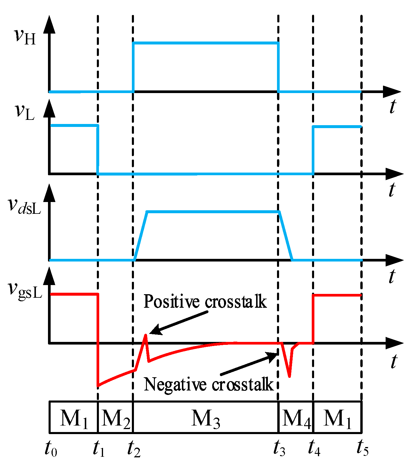
In this paper, the eGaNL is taken as an example to demonstrate how the proposed gate driver works. Figure 3 shows the drive signals vH for eGaNH and vL for eGaNL, along with the drain-source vdsL and gate-source vgsL voltage waveforms of eGaNL. The working mechanism of the proposed gate driver can be described as follows.
M1 [t0~t1] [t4~t5]: The circuit operating mode is shown in Figure 4a. At this stage, the drive voltage of eGaNH is low and it is turned off, while the drive voltage of eGaNL is high and it is turned on. Additionally, the bus voltage VDC is applied on both ends of the eGaNH drain-source pole. The drive voltage amplitude is equal to the sum of the current-limiting resistor R3’s voltage drop, diode D3’s voltage drop, the voltage regulator diode D4’s regulated value, and the charging voltage of capacitor C1. During this period, the drive voltage charges capacitor C1, polarizing it with the left terminal negative and the right terminal positive.
M2 [t1~t2]: The circuit operating mode is shown in Figure 4b. This phase is the transition phase of the eGaNH and eGaNL; the drive voltages of eGaNH and eGaNL are low, and they are turned off. The charge entering capacitor C1 in the turn-on phase is released through resistor R2 on the one hand, and through drive resistor R4 and current-limiting resistor R3 on the other, constituting two discharge circuits. Diode D3 and voltage regulator diode D4 are in the cut-off state, and the discharge loop forms a negative voltage across the CgsL, which accelerates the turn-off of eGaNL.
M3 [t2~t3]: The circuit operating mode is shown in Figure 4c. At this stage, the drive voltage of eGaNH is high, and it is turned on. The drive voltage of eGaNL is low, keeping it off. The vdsL of eGaNL gradually rises to the bus voltage VDC. During this period, diodes D1 and D4 are in the cut-off state, blocking Miller current. Miller current, on the one hand, flows through resistors R3 and R4 to drive the GNDL; on the other hand, it flows through the gate-source capacitance CgsL, capacitor C1, and resistor R2 to the GNDL. Currently, the voltage across capacitor C1 counteracts the voltage across resistors R3 and R4, thereby reducing the positive crosstalk. After the positive crosstalk, the eGaNL remains turned off, capacitor C1 is discharged through resistor R2, and the gate-source voltage returns to 0 V.
M4 [t3~t4]: The circuit operating state is shown in Figure 4d. At this stage, the eGaNH begins to be turned off at t3. The drive signal of eGaNL is low, and it is turned off. Consequently, the VDSL gradually decreases from the bus voltage VDC to 0 V. At this stage, diodes D3 and D2 are in the cut-off state, blocking the Miller current. In high-frequency conditions, the impedance of capacitor C1 is very low and can be approximated as that of a wire. In this stage, resistance R2 is short-circuited by capacitance C1. Miller current flows through capacitor C1, current-limiting resistor R3, and drive resistor R4 to load L on one hand, and through capacitor C1, resistor R1, and diode D1 to load L on the other hand. At this time, the two branches of the Miller current are in a parallel relationship, which reduces the voltage drop compared to a single circuit composed of a large resistor, thereby mitigating negative crosstalk.

4. Component Parameters Design

The crosstalk suppression capability of the proposed gate driver directly depends on the parameter values of the components in the circuit. The derivation of the range of the main component parameters is presented as follows.

4.1. Voltage Regulator Diode D2

When the eGaNH is turned off and the eGaNL is turned on, the eGaNL drive voltage vgL charges the capacitor C1, and the voltage at the two terminals of C1 is determined by the regulator value VD2 of D2, which is connected in parallel with it. Capacitor C1 begins to discharge through resistor R2 at t1. It can be obtained:
v C 1 ( t 1 ) = V D 2 v C 1 = R 2 C 1 d v C 1 d t
The collation leads to:
v C 1 = V D 2 e t R 2 C 1
Then the voltage Vt2 across C1 at t2 is:
V t 2 = V D 2 e Δ T 2 R 2 C 1
where ΔT2 is the duration of the transition phase (from t1 to t2).
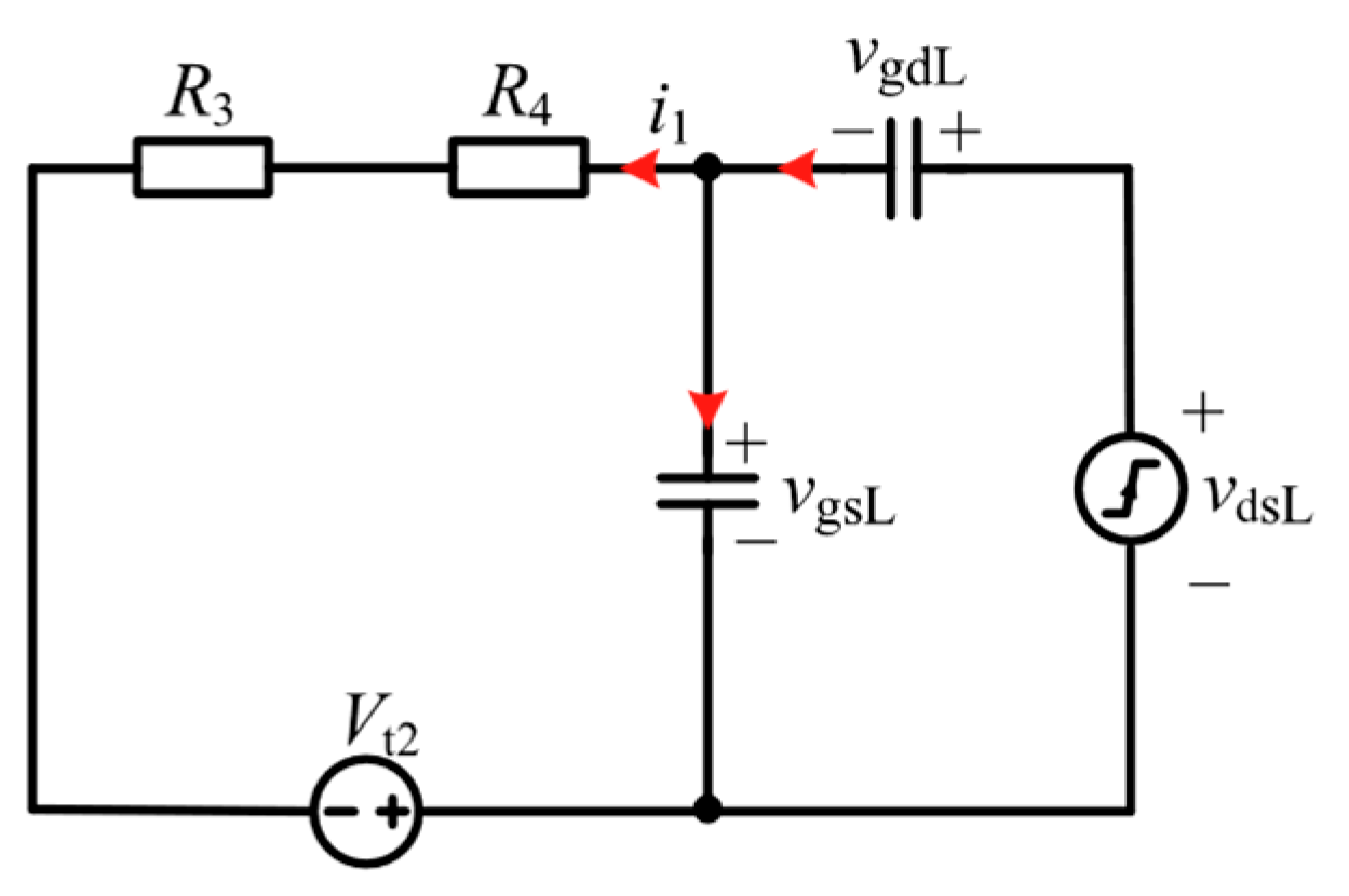
Since the positive crosstalk suppression phase is much smaller than the time constant R2C1 of capacitor C1 discharging through resistor R2, it can be assumed that the voltage on capacitor C1 is unchanged in this phase, and its value is the voltage of C1 at t2. The equivalent circuit is shown in Figure 5, the red arrow indicates the direction of current flow. From Figure 5:
v gsL + v gdL = v dsL = a t i 1 = C gdL d v gdL d t C gsL d v gsL d t R 3 + R 4 i 1 v gsL V t 2 = 0
The collation leads to:
v gsL = ( a R gL C gdL V t 2 ) ( 1 e t C issL R gL )
where RgL = R3 + R4, CissL = CgsL + CgdL. From Equation (8), vgsL is positively correlated with t; when tVDC/a, vgsL reaches its maximum value. Currently, it is necessary to meet the condition that the positive crosstalk voltage peak is less than the threshold voltage of the device.
a M R gL C gdL M V D 2 e Δ T 2 R 2 C 1 < V th
where Vth represents the device’s threshold voltage, M is for:
M = 1 e V DC a C issL R gL
Capacitor C1 is discharged through resistor R2 during t2~t3. To prevent the voltage of C1 from aggravating the negative crosstalk, the voltage at both ends of C1 needs to be restored to 0 V before t3, when the negative crosstalk is generated. According to the RC discharge characteristics, the period ΔT3 from t2 to t3 is defined as five times the discharge time constant R2C1:
Δ T 3 = 5 R 2 C 1
Combining Equations (9) and (11) yields:
V D 2 > ( a R gL C gdL V th M 1 ) e 5 Δ T 2 Δ T 3
The negative voltage of capacitor C1 cannot exceed the reverse breakdown voltage of the device gate, so the value of VD2 is as small as possible under the condition of satisfying Equation (12) to reduce the reverse voltage on the device gate.

4.2. Capacitor C1

The value of capacitor C1 needs to be selected considering the following two factors. The first factor is that the charge stored in C1, QC1, should be larger than the total charge QGL of the gate capacitance of the device. When the device is turned off, the polarity of the voltage across C1 is opposite to that of the gate parasitic capacitance, and C1 must accommodate the QGL. The second factor is that the sum of the energy stored in C1 and the energy required by the gate of the device should be smaller than the output energy of the driver IC, ensuring the reliable functioning of the driver IC.
For the first factor, to ensure that the amount of charge QC1 stored in C1 at device turn-off is sufficient to counteract the total gate charge QGL of the eGaNL, QC1 must satisfy the following condition.
Q C 1 = C 1 V D 2 > Q GL
For the second factor, the following condition must be satisfied to ensure that the driver’s IC works properly.
P D > α ( P C 1 + P GL )
where PD is the supplied energy of the driver IC, PC1 is the energy stored in C1, PGL is the energy required for the gate of the device, and α is the safety margin factor (α > 1). PC1 and PGL can be expressed as follows [30]:
P C 1 = C 1 V D 2 2 f s 2 P GL = V GL Q GL f s
where fs is the switching frequency of the eGaNL, and VGL is the drive voltage of the eGaNL. Combining with Equations (13)–(15), the range of values of C1 is determined as follows:
Q GL V D 2 < C 1 < 2 ( P D α V GL Q GL f s ) α V D 2 2 f s
Under the condition that Equation (16) is satisfied, the value of C1 should be as small as possible. This will shorten the time for C1 to discharge, enabling the eGaN device to operate at a higher switching frequency. Meanwhile, combining with Equation (11), the time constant of C1 discharge, R2C1, and the device’s switching frequency fs should satisfy the following equation:
5 R 2 C 1 < 1 f s

4.3. Resistor R1

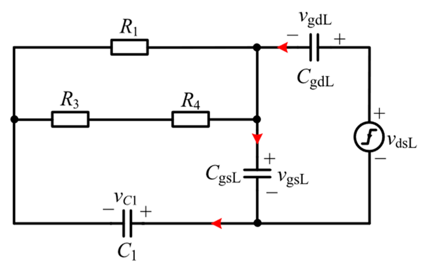
Due to the unidirectional conductivity of diode D1, resistor R1 and diode D1 operate only in the negative crosstalk suppression stage. The forward voltage drop of diode D1 is small and is ignored for ease of calculation. The equivalent circuit of the negative crosstalk phase is presented in Figure 6, the red arrow indicates the direction of current flow.
Writing Kirchhoff’s laws for Figure 6 yields:
C 1 d v C 1 d t + C gdL d v gdL d t = C gsL d v gsL d t v dsL = v gdL + v gsL = V DC a t v gsL + v C 1 R 1 + v gsL + v C 1 R 3 + R 4 = C 1 d v C 1 d t
The collation leads to:
v gsL = a C gdL t B a C 1 2 C gdL R B B 2 R A ( 1 e B R A t C 1 C issL R B )
where B = C1 + CissL, RA = R1 + R3 + R4, RB = R1 (R3 + R4). From Equation (19), the vgsL of the eGaNL increases with the increase in t, when tVDC/a, vgsL reaches its maximum value vgsLm:
v gsLm = V DC C gdL B a C 1 2 C gdL R B B 2 R A ( 1 e B R A V DC a C 1 C issL R B )
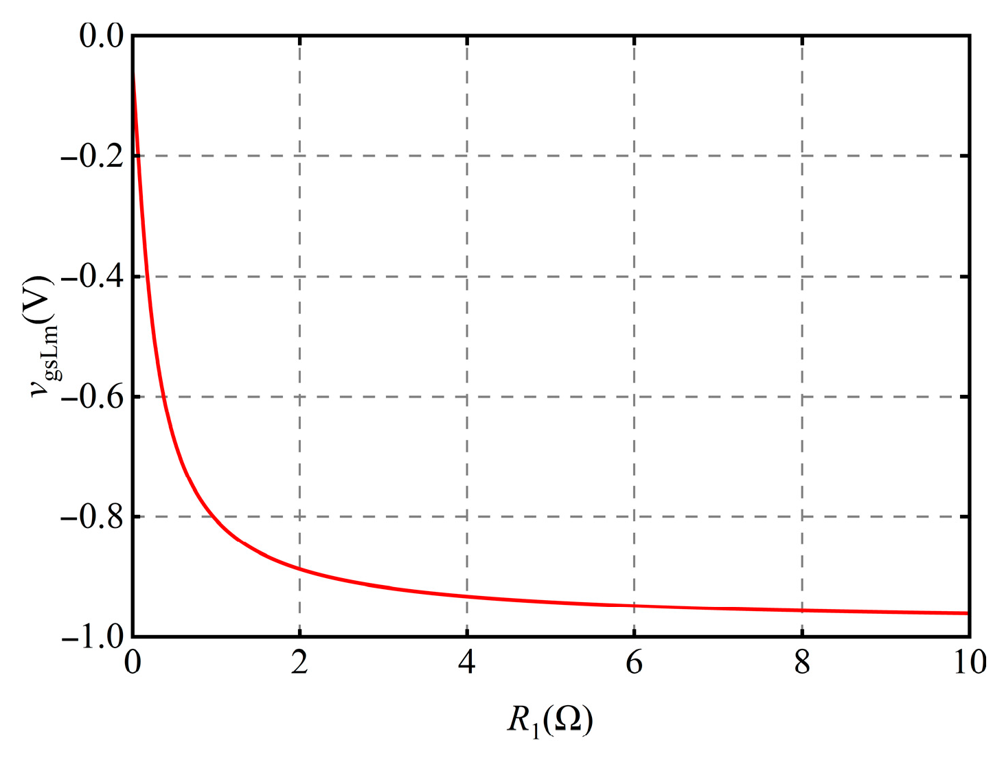
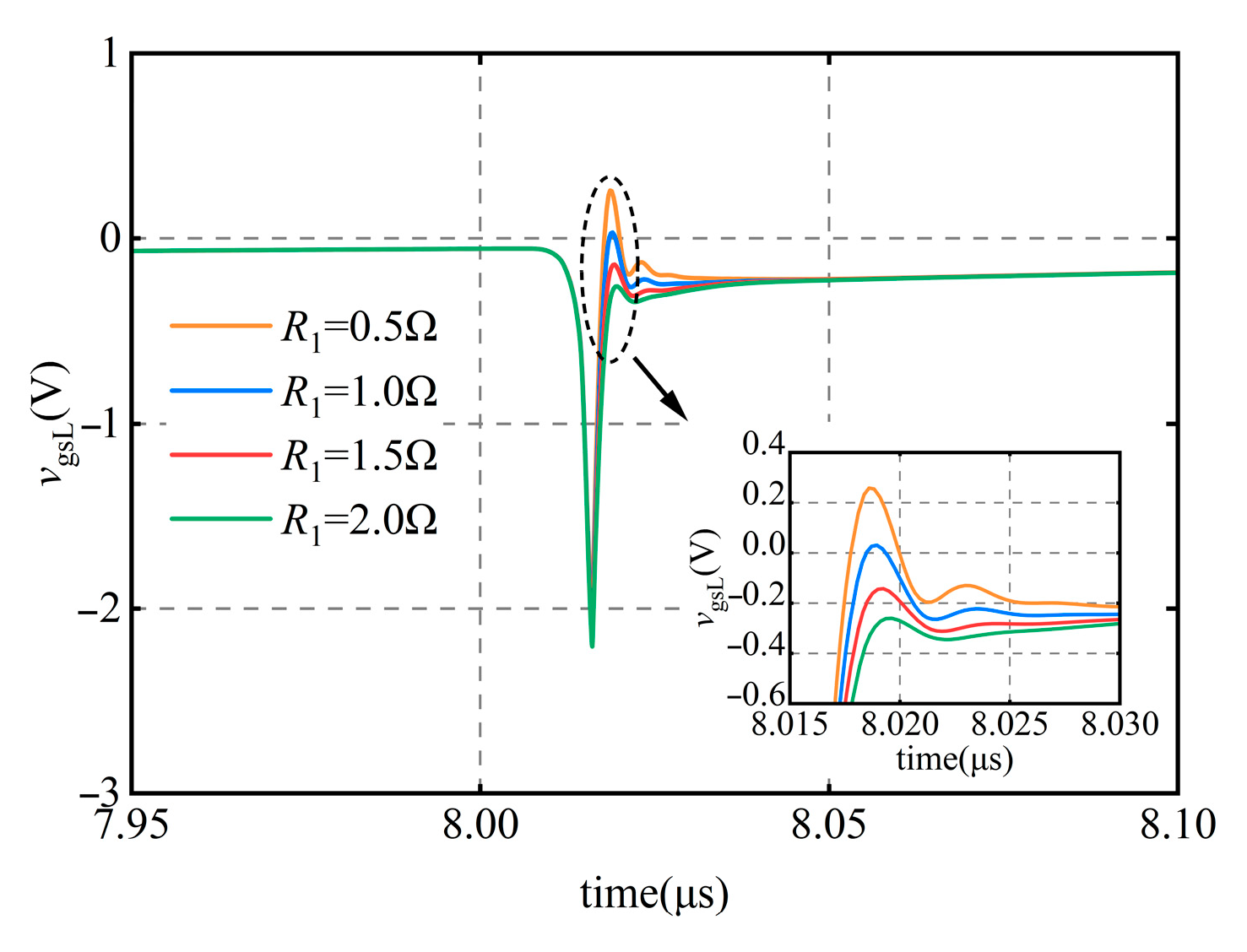
Figure 7 shows the correlation between resistor R1 and the peak negative crosstalk voltage vgsLm, from which it can be obtained that the value of vgsLm is positively correlated with R1. Therefore, the smaller the resistance value of R1, the better. At the same time, as R1 decreases, the impedance of the gate driver decreases, increasing the device gate-source oscillation. This results in the positive oscillation being too large and exceeding the device threshold voltage, thereby increasing the risk of device misconduct. The relationship between the device gate-source oscillation and R1 is shown in Figure 8. Therefore, both factors must be considered when selecting the value of R1.

4.4. Other Component Parameters

For the resistor R2, which, together with capacitor C1, determines the discharge rate of C1, it is also necessary to ensure that capacitor C1 discharges the stored charge and returns to 0 V at t3. With the value of capacitor C1 determined, the following equation can be derived from Equation (11).
R 2 = Δ T 3 5 C 1
For the voltage regulator diode D4, its regulated value, VD4, and the forward conduction voltage drop, VD3, of diode D3, together form the drive voltage, VGL, of the device. Therefore, it can be obtained that:
V D 4 = V GL V D 3
For the resistor R3, it acts as a current-limiting resistor for the voltage regulator diodes D2 and D4, ensuring that the voltage regulator diodes can function properly. Therefore, the value of resistor R3 can be determined by the following equation:
R 3 = V ccL V D 2 V D 4 V D 3 I Z
where VD2 and VD4 are, respectively, the regulated values of regulator diodes, and Iz is the current of the regulator diode during normal operation.
For the resistor R4, since it and resistor R3 together form the drive resistance RgL of the device, it can be obtained that:
R 4 = R gL R 3
For diodes D1 and D3, their role is to enable unidirectional current flow in the branch. D1 is used to prevent current from flowing through resistor R1 and affecting the turn-on speed when the device is turned on. Diode D3 is used to prevent capacitor C1 from discharging rapidly through paths C1-D4-D3-R3, which affects the effectiveness of the negative voltage suppression and the reduction of positive crosstalk of C1.
To adapt to the fast-switching characteristics of the eGaN HEMT, Schottky diodes are used for D1 and D3. The maximum reverse peak voltages VRM1 and VRM3 of the two diodes are selected based on the following: for D1, the maximum reverse voltage is the sum of the device drive voltage VGL and the maximum negative voltage of capacitor C1, which is the regulated voltage value VD2 of D2; for D3, the maximum reverse voltage is the maximum negative voltage of capacitor C1. The following equation can be derived:
V RM 1 > V GL + V D 2 V RM 3 > V D 2
For the auxiliary power supply VccL, in order to make D2 work normally and the eGaNL gate to reach the set drive voltage VGL, it is necessary to satisfy the following:
V ccL = β ( V GL + V D 2 )
Considering that there will be some voltage drops inside the driver IC and on resistor R3 when the device is operating, VccL needs to be designed with a margin factor β (β > 1).

5. Experimental Verification

The effect of the proposed gate driver on the suppression of both positive and negative crosstalk, as well as on the switching speed of the device, is tested using a double-pulse test platform. The performance of the proposed gate driver in practical engineering is validated by a synchronous Buck test platform. GS61008P was selected as the test device, which has a rated drain voltage of 100 V, a rated drain current of 90 A, and a total gate charge of 8 nC. To satisfy the test requirements, the oscilloscope is TDS3054C. The voltage and current waveforms are measured using a voltage probe (P6139B) and a current probe (TCPA300).

5.1. Double-Pulse Test

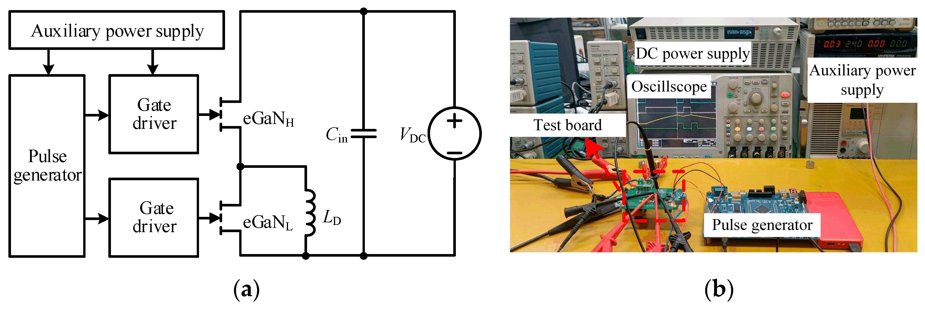
The setup of the double-pulse test platform is shown in Figure 9a, where eGaNH is an active tube and eGaNL is a passive tube; VDC is the input power supply, which is 50 V; Cin is the DC link capacitor, which is 330 μF; LD is the load inductance, which is 50 μH.
For the regulator diode D2, the MMSZ5226BT1G with a regulated value of 3.3 V is selected according to Equation (12). For the regulator diode D4, the MMSZ5232A with a regulated voltage of 5.6 V is selected, as recommended by the datasheet and Equation (22) for a 6 V drive voltage. Considering the reverse voltage stress on the diodes D1 and D3, Schottky diodes 1N5818 are selected for D1 and D3. According to the technical instruction recommendation, one 10 Ω drive resistor is set after the driver IC of the conventional gate driver for the control group [31]. According to Equations (16)–(24), the value of capacitor C1 is 6.8 nF, and the values of resistors R2 to R4 are 59 Ω, 1 Ω, and 9 Ω, respectively. The supply voltage VccL in the conventional gate driver is set to 6 V. According to Equation (26), the supply voltage VccL in the proposed gate driver is set to 12 V.
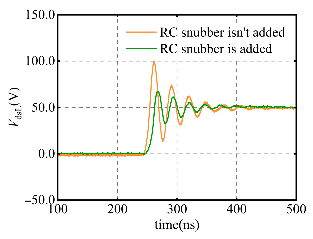
During the switching process of the device, due to the interaction between the parasitic inductance and capacitance of the circuit, overshoot and ringing phenomena occur in the drain-source voltage of the device, increasing the risk of drain-source breakdown and thereby affecting the circuit’s safety. In this paper, the method of connecting an RC snubber in parallel with the drain and source of the device is adopted to reduce the ringing. The drain-source waveforms before and after adding the RC snubber are shown in Figure 10. From the results, it is evident that the maximum value of the ring is reduced by 33 V.
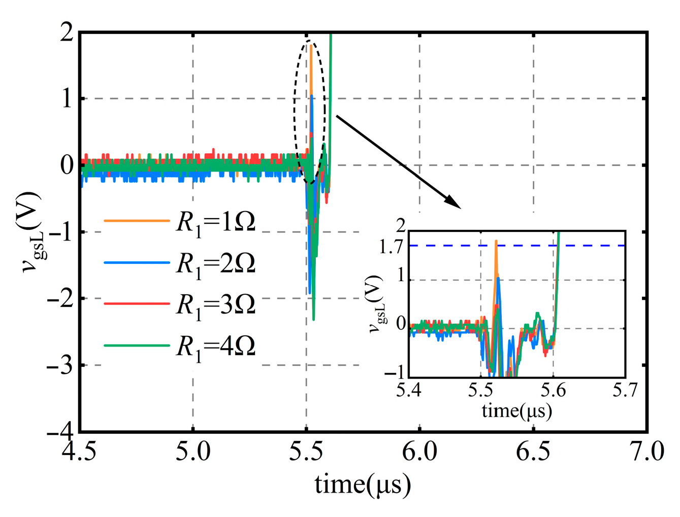
Figure 11 shows the gate voltage oscillation under different values of R1 in the experiment. When R1 is configured to 1 Ω, the positive gate voltage oscillation reaches 1.82 V, which exceeds the device’s threshold voltage of 1.7 V. Therefore, the device is at risk of misconduct. To prevent device misconduct and minimize negative crosstalk voltage, the value of R1 is ultimately set to 2 Ω.
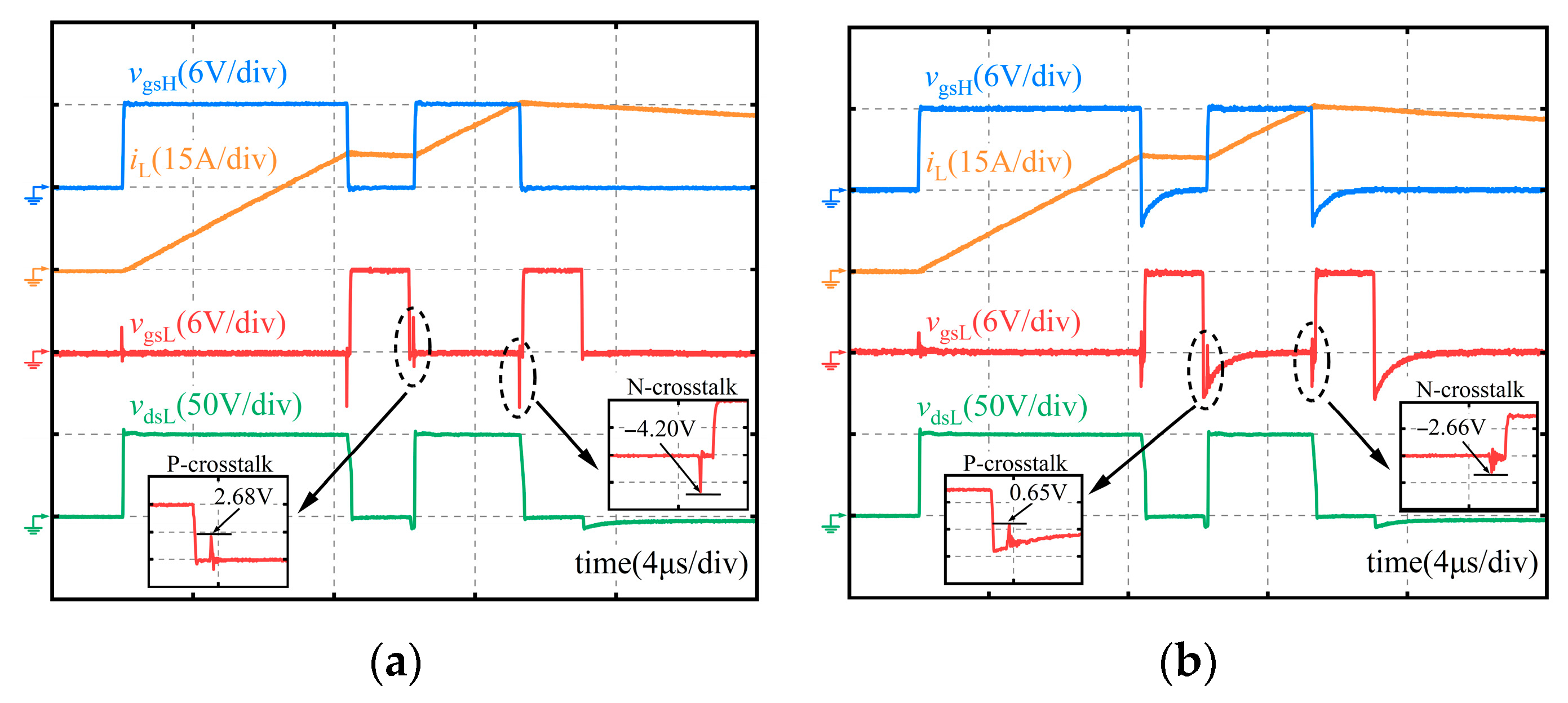
The double-pulse test results of the devices under the conventional gate driver and the proposed gate driver are shown in Figure 12. A 2.03 V reduction in the positive crosstalk peak is achieved by the proposed gate driver compared to the conventional one, with its positive crosstalk peak falling below the 1.7 V threshold voltage of the GS61008P, thereby reducing the risk of device misconduct. The negative crosstalk spike of the proposed gate driver is reduced by 1.54 V compared to the conventional one, which validates the driver’s negative crosstalk suppression capability.
The proposed gate driver is also applicable to other eGaN devices with different gate charges, such as the GS66508P, which has a gate charge of 5.8 nC. Since the GS66508P can operate at higher voltage levels, larger crosstalk spikes may occur. To achieve better suppression, a regulator diode with a higher regulated voltage should be selected for D2 to provide a larger negative voltage.
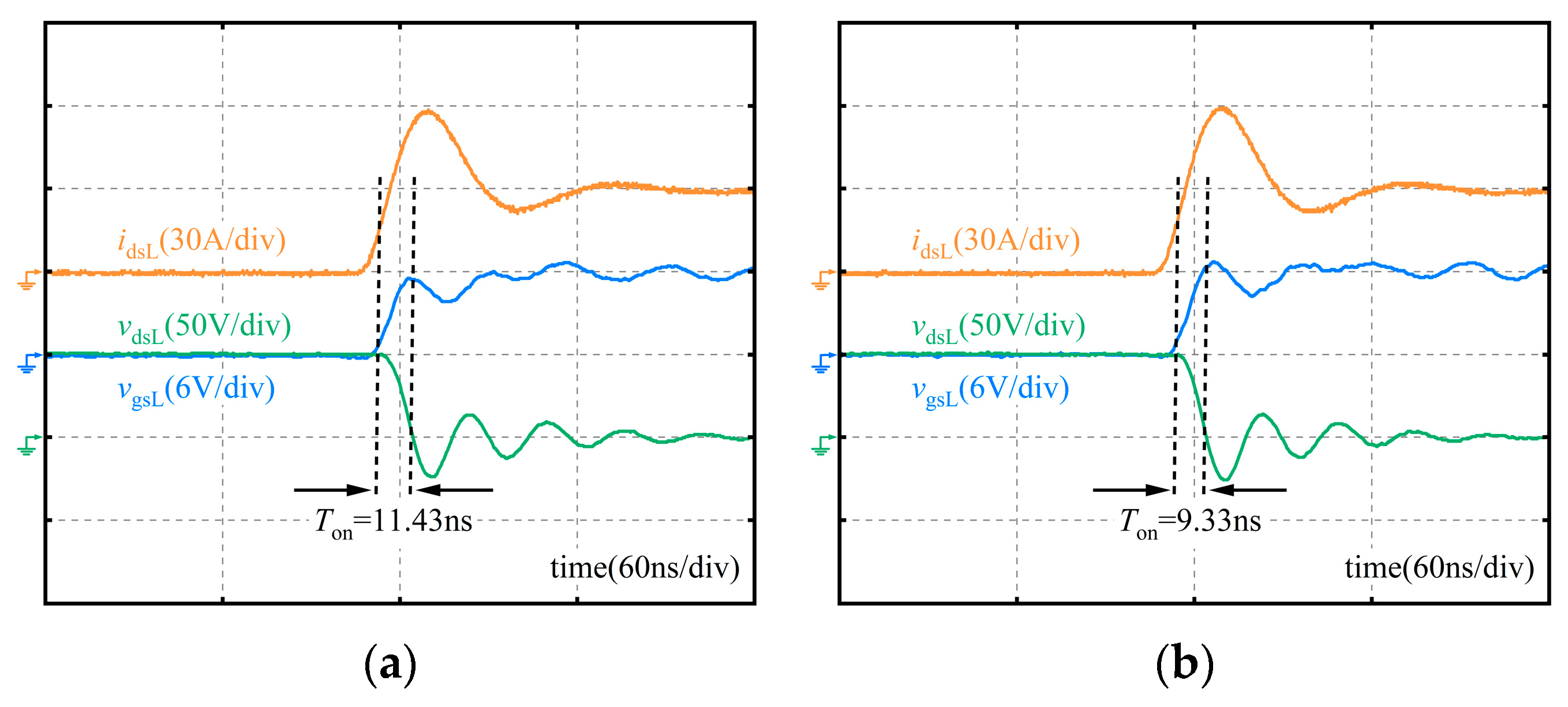
To investigate the effect of the proposed gate driver on the switching performance of the device under test, the switching waveforms of the device are compared under both the conventional gate driver and the proposed gate driver. The turn-on waveforms of the device under these two circuits are shown in Figure 13, from which it can be observed that the turn-on time of the device under the traditional gate driver is 11.43 ns, and the turn-on time under the proposed gate driver is 9.33 ns.
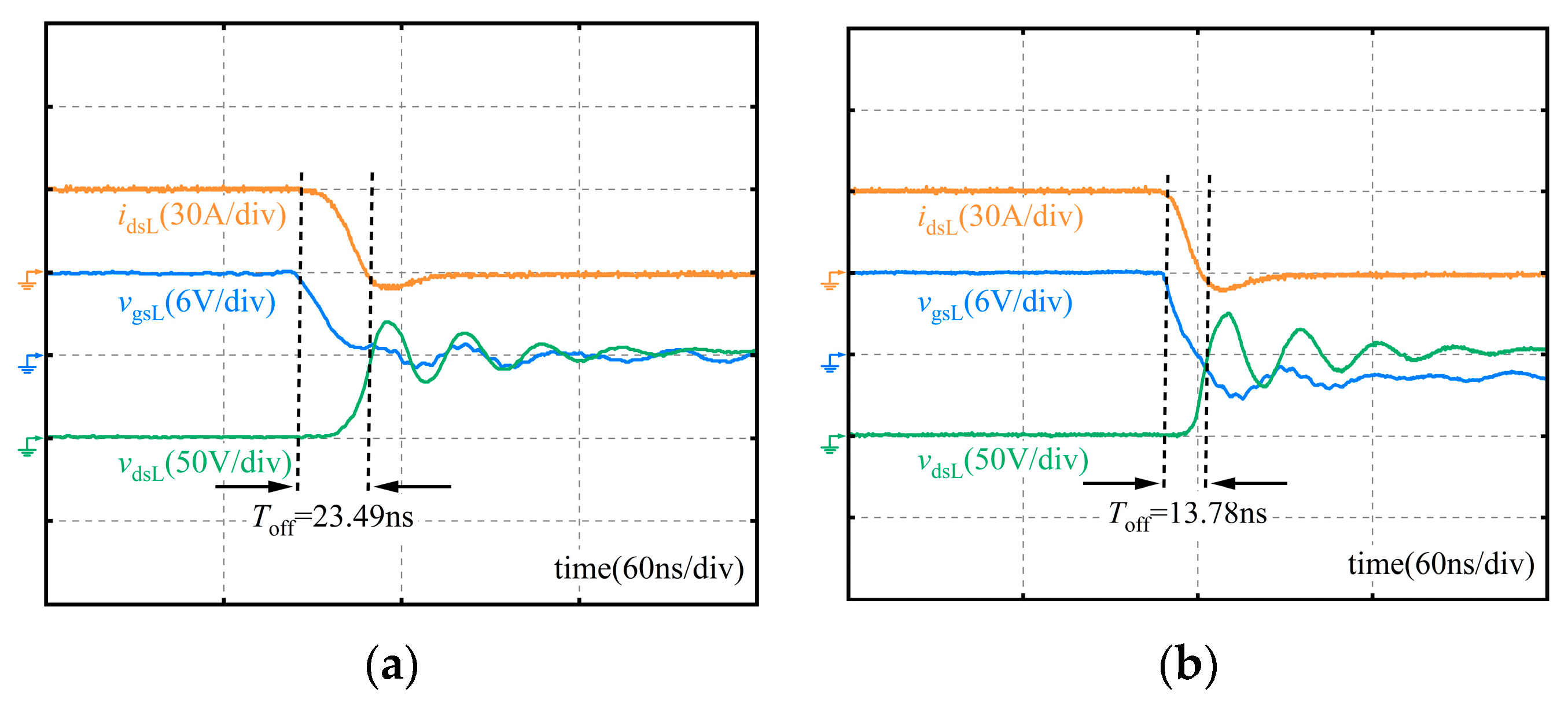
The turn-off waveforms of the device tested under these two gate drivers are shown in Figure 14, from which it can be seen that the turn-off time is 23.49 ns under the conventional gate driver and 13.78 ns under the proposed one. Under the proposed gate driver’s operation, the device’s turn-off speed is enhanced by approximately 41.34% compared to the conventional driver, as C1 enables negative-voltage turn-off of the device.
To investigate the impact of the proposed gate driver on the switching loss of the device, the switching loss of the device is calculated when tested with these two drivers. The turn-on loss is 12.09 μJ and 10.87 μJ in the conventional gate driver and the proposed one, respectively, indicating that the proposed circuit has little impact on the device’s turn-on loss; while the turn-off loss is 1.51 μJ and 0.35 μJ, respectively, indicating that the proposed gate driver is capable to significantly reduce the turn-off loss by 76.82%.

5.2. Synchronous Buck Test

The mechanism of the synchronous Buck test platform is shown in Figure 15a, where eGaNH is the active tube and eGaNL is the passive tube; VDC is the input power supply, which is 50 V; Cin is DC link capacitor, which is 330 μF; LD is the load inductance, which is 20 μH; Co is the output voltage regulator capacitance, which is 150 μF; and RL is the load resistor, which is 1.8 Ω. The synchronous Buck circuit operates at a 500 kHz frequency in the testing of this experiment.
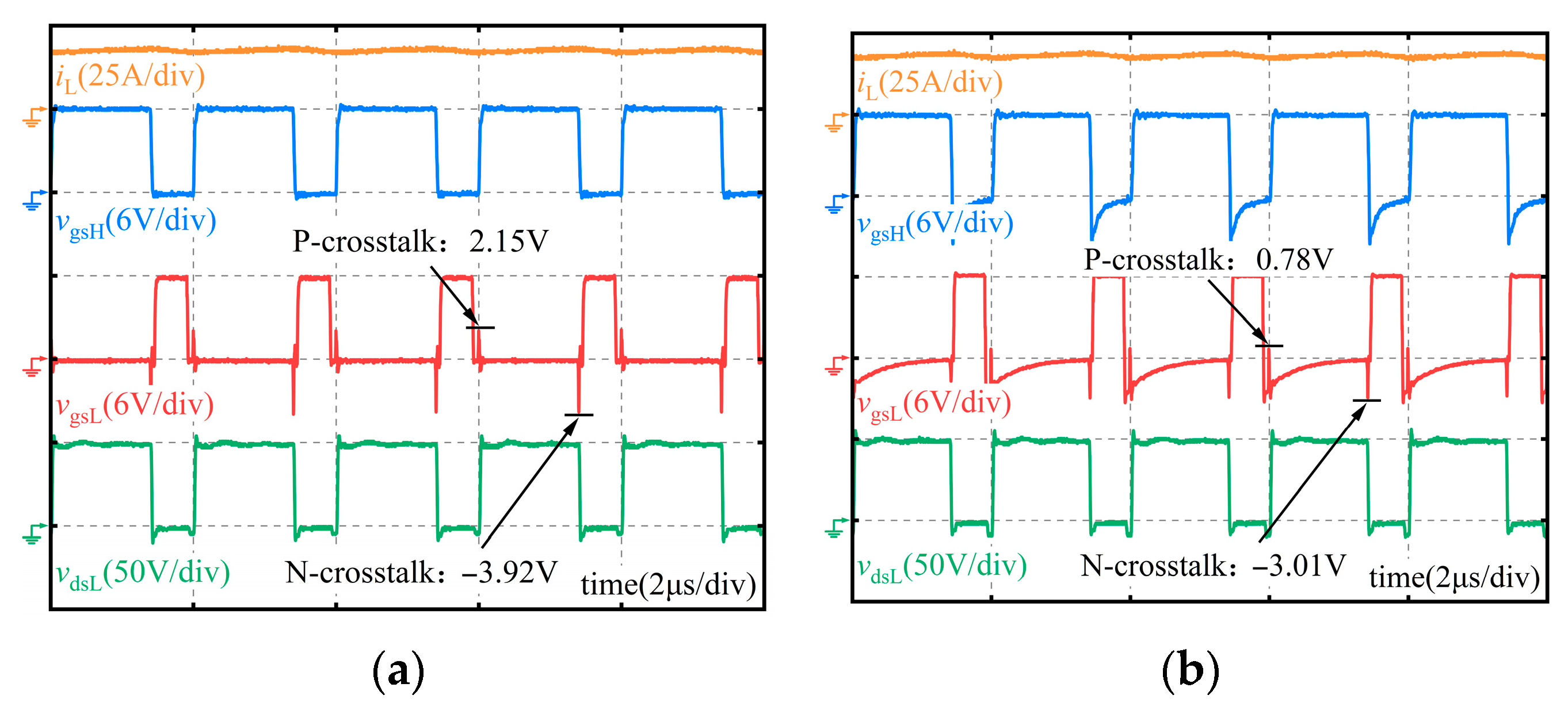
The synchronous Buck test results are shown in Figure 16. The positive crosstalk peak value of the proposed gate driver is reduced by 1.37 V compared to the conventional gate driver, and the negative crosstalk peak value is decreased by 0.91 V. Crosstalk suppression capability is more evident in double-pulse tests than in synchronous Buck circuits. However, the result demonstrates that the proposed gate driver presents a positive crosstalk peak value of less than 1.7 V and a negative crosstalk voltage peak value of more than −10 V under both test conditions, which meets the safe operation requirements.

6. Discussion

To illustrate the characteristics of the proposed gate driver, this paper compares some typical crosstalk suppression circuits by evaluating them from three perspectives: reducing device turn-on speed, mitigating negative crosstalk, and increasing control complexity, as shown in Table 1.
  • From the perspective of reducing the device turn-on speed, the circuits proposed in [23,24] require charging the auxiliary capacitor placed in parallel with the gate, which in turn reduces the device turn-on speed. The circuits proposed in [27,28,29] do not have auxiliary capacitors in parallel, which does not affect the device turn-on speed. In this paper, the structure without an auxiliary capacitor in parallel is also employed, and its effect on the device’s turn-on speed is negligible.
  • From the perspective of exacerbating negative crosstalk, the circuits proposed in [23,28] do not provide an effective discharge path for the negative voltage capacitor, which will exacerbate the gate negative crosstalk and increase the risk of gate reverse breakdown. The circuit proposed in [29] uses an auxiliary MOSFET to clamp the negative voltage without exacerbating the negative crosstalk. The circuits proposed in [27] provide a discharge path for the negative voltage capacitor, allowing for negative voltage recovery without affecting gate-to-negative crosstalk. In this paper, this idea is also adopted to avoid exacerbating the gate negative crosstalk.
  • From the perspective of increasing control complexity, the circuits proposed in [27,29] require the introduction of MOSFET, which increases the control complexity. In contrast, the circuits proposed in this paper and the other literature do not require additional control, which improves the ease of application.

7. Conclusions

This paper provides a brief analysis of the crosstalk problem in the half-bridge circuit. It proposes a gate driver that suppresses both positive and negative crosstalk, addressing the limitations of existing crosstalk suppression circuits that require additional control signals or exacerbate negative crosstalk. Double-pulse experiments are conducted to validate the crosstalk suppression capability of the proposed gate driver, which achieves shorter device turn-off time and lower loss compared to the conventional driver. By building a synchronous Buck circuit, the practical value of the proposed circuit is validated in real working conditions, which provides a basis for further improvement in the gate driver.

Author Contributions

Writing—original draft: L.Z. and K.W.; writing—reviewing and editing: L.Z. and S.G.; supervision: K.W. and B.Z. All authors have read and agreed to the published version of the manuscript.

Funding

This work was funded by Hubei Natural Science Foundation (2024AFB234) and Yichang Natural Science Research Project (A23-2-019).

Institutional Review Board Statement

Not applicable.

Informed Consent Statement

Not applicable.

Data Availability Statement

The original contributions presented in this study are included in the article. Further inquiries can be directed to the corresponding author.

Conflicts of Interest

The authors declare no conflicts of interest.

References

  1. Khadar, R.A.; Liu, C.; Soleimanzadeh, R.; Matioli, E. Fully Vertical GaN-on-Si power MOSFETs. IEEE Electron. Device Lett. 2019, 40, 443–446. [Google Scholar] [CrossRef]
  2. Wang, K.; Zhu, Y.; Zhao, H.; Zhao, R.; Zhu, B. Steady-State Temperature-Sensitive Electrical Parameters’ Characteristics of GaN HEMT Power Devices. Electronics 2024, 13, 363. [Google Scholar] [CrossRef]
  3. Manandhar, M.B.; Matin, M.A. Comparative Modelling and Thermal Analysis of AlGaN/GaN Power Devices. J. Low Power Electron. Appl. 2021, 11, 33. [Google Scholar] [CrossRef]
  4. Yang, Y.; Zhu, B.; She, X.; Wang, K.; Liu, A. A Family of Bipolar DC–DC Converters With Interpolar Voltage Self-Balancing Based on FB-BVMs for BLVDC Microgrid. IEEE Trans. Ind. Electron. 2025. [Google Scholar] [CrossRef]
  5. Faraji, R.; Farzanehfard, H.; Kampitsis, G.; Mattavelli, M.; Matioli, E.; Esteki, M. Fully Soft-Switched High Step-Up Nonisolated Three-Port DC–DC Converter Using GaN HEMTs. IEEE Trans. Ind. Electron. 2020, 67, 8371–8380. [Google Scholar] [CrossRef]
  6. Wen, H.; Gong, J.; Zhao, X.; Yeh, C.S.; Lai, J.S. Analysis of Diode Reverse Recovery Effect on ZVS Condition for GaN-Based LLC Resonant Converter. IEEE Trans. Power Electron. 2019, 34, 11952–11963. [Google Scholar] [CrossRef]
  7. Murukesan, K.; Efthymiou, L.; Udrea, F. On the challenges of reliable threshold voltage measurement in ohmic and schottky gate p-GaN HEMTs. IEEE J. Electron. Devices Soc. 2021, 9, 831–838. [Google Scholar] [CrossRef]
  8. Avraham, T.; Dhyani, M.; Bernstein, J.B. Reliability Challenges, Models, and Physics of Silicon Carbide and Gallium Nitride Power Devices. Energies 2025, 18, 1046. [Google Scholar] [CrossRef]
  9. Yang, Y.; Zhu, B.; She, X.; Wang, K.; Liu, A. A Family of Voltage Balancers with Fault-Tolerance and Interpolar Voltage Self-Balancing Ability for Bipolar DC Power Systems. IEEE Trans. Transp. Electrif. 2025. [Google Scholar] [CrossRef]
  10. Chen, J.; Luo, Q.; Huang, J.; He, Q.; Du, X. A Complete Switching Analytical Model of Low-Voltage eGaN HEMTs and Its Application in Loss Analysis. IEEE Trans. Ind. Electron. 2020, 67, 1615–1625. [Google Scholar] [CrossRef]
  11. Xie, R.; Yang, X.; Xu, G.; Wei, J.; Wang, Y.; Wang, H.; Tian, M.; Zhang, F.; Chen, W.; Wang, L.; et al. Switching transient analysis for normally-off GaN transistor with p-GaN gate in a phase-leg circuit. IEEE Trans. Power Electron. 2019, 34, 3711–3728. [Google Scholar] [CrossRef]
  12. Zhang, W.; Wang, F.; Costinett, D.J.; Tolbert, L.M.; Blalock, B.J. Investigation of gallium nitride devices in high-frequency LLC resonant converters. IEEE Trans. Power Electron. 2017, 32, 571–583. [Google Scholar] [CrossRef]
  13. Wang, X.; Zhao, Q.; Zhao, Z.; Meng, F. Full-Bridge DC-DC Converter with Synchronous Rectification Based on GaN Transistors. J. Low Power Electron. Appl. 2025, 15, 25. [Google Scholar] [CrossRef]
  14. Belkacemi, K.; Hocine, R. Efficient 3D-TLM Modeling and Simulation for the Thermal Management of Microwave AlGaN/GaN HEMT Used in High Power Amplifiers SSPA. J. Low Power Electron. Appl. 2018, 8, 23. [Google Scholar] [CrossRef]
  15. Xie, R.; Wang, H.; Tang, G.; Yang, X.; Chen, K.J. An Analytical Model for False Turn-On Evaluation of High-Voltage Enhancement-Mode GaN Transistor in Bridge-Leg Configuration. IEEE Trans. Power Electron. 2017, 32, 6416–6433. [Google Scholar] [CrossRef]
  16. Riazmontazer, H.; Rahnamaee, A.; Mojab, A.; Mehrnami, S.; Mazumder, S.K.; Zefran, M. Closed-loop control of switching transition of SiC MOSFETs. In Proceedings of the 2015 IEEE Applied Power Electronics Conference and Exposition (APEC), Charlotte, NC, USA, 15–19 March 2015; pp. 782–788. [Google Scholar]
  17. Zushi, Y.; Sato, S.; Matsui, K.; Murakami, Y.; Tanimoto, S. A novel gate assist circuit for quick and stable driving of SiC-JFETs in a 3-phase inverter. In Proceedings of the 2012 Twenty-Seventh Annual IEEE Applied Power Electronics Conference and Exposition (APEC), Orlando, FL, USA, 5–9 February 2012; pp. 1734–1739. [Google Scholar]
  18. Huang, X.; Liu, Z.; Lee, F.C.; Li, Q. Characterization and Enhancement of High-Voltage Cascode GaN Devices. IEEE Trans. Electron Devices 2015, 62, 270–277. [Google Scholar] [CrossRef]
  19. Hu, K.; Yang, M.; Zhang, X. A Multilevel Self-Driving Gate Driver of SiC MOSFET for Crosstalk Suppression Considering Common-Source Inductance. IEEE Trans. Power Electron. 2025, 40, 906–919. [Google Scholar] [CrossRef]
  20. Zhang, B.; Wang, S. A crosstalk suppression technique for SiC MOSFETs in the bridge-leg configuration. In Proceedings of the 2020 IEEE Applied Power Electronics Conference and Exposition (APEC), New Orleans, LA, USA, 15–19 March 2020; pp. 1513–1520. [Google Scholar]
  21. Zhang, Z.; Dix, J.; Wang, F.F.; Blalock, B.J.; Costinett, D.; Tolbert, L.M. Intelligent Gate Drive for Fast Switching and Crosstalk Suppression of SiC Devices. IEEE Trans. Power Electron. 2017, 32, 9319–9332. [Google Scholar] [CrossRef]
  22. Zhang, Z.; Wang, F.; Tolbert, L.M.; Blalock, B.J. Active Gate Driver for Crosstalk Suppression of SiC Devices in a Phase-Leg Configuration. IEEE Trans. Power Electron. 2014, 29, 1986–1997. [Google Scholar] [CrossRef]
  23. Wang, J.; Chung, H.S.H. A novel RCD level shifter for elimination of spurious turn-on in the bridge-Leg configuration. IEEE Trans. Power Electron. 2015, 30, 976–984. [Google Scholar] [CrossRef]
  24. Li, B.; Zhang, G.; Li, C.; Wang, G.; Liu, S.; Xu, D. Crosstalk suppression method for GaN-based bridge configuration using negative voltage self-recovery gate drive. IEEE Trans. Power Electron. 2022, 37, 4406–4418. [Google Scholar] [CrossRef]
  25. Lu, Z.; Li, C.; Wu, H.; Li, W.; He, X.; Li, S. Design of Active SiC MOSFET Gate Driver for Crosstalk Suppression Considering Impedance Coordination between Gate Loop and Power Loop. In Proceedings of the 2019 IEEE Applied Power Electronics Conference and Exposition (APEC), Anaheim, CA, USA, 17–21 March 2019; pp. 986–990. [Google Scholar]
  26. Liu, C.; Zhang, Z.; Liu, Y.; Si, Y.; Lei, Q. Smart Self-Driving Multilevel Gate Driver for Fast Switching and Crosstalk Suppression of SiC MOSFETs. IEEE J. Emerg. Sel. Top. Power Electron. 2020, 8, 442–453. [Google Scholar] [CrossRef]
  27. Wu, X.; Zaman, H.; Wu, P.; Jia, R.; Zhao, X.; Wu, X. A Quasi-Multilevel Gate Driver for Fast Switching and Crosstalk Suppression of SiC Devices. IEEE Access 2020, 8, 191403–191412. [Google Scholar] [CrossRef]
  28. Zaman, H.; Wu, X.; Zheng, X.; Khan, S.; Ali, H. Suppression of switching crosstalk and voltage oscillations in a SiC MOSFET based half-bridge converter. Energies 2018, 11, 3111. [Google Scholar] [CrossRef]
  29. Qiu, Z.; Li, H.; Jiang, Y.; Shao, T.; Yang, Z.; Wang, J.; Zhang, Z. An Intelligent Three-level Active Gate Driver for Crosstalk Suppression of SiC MOSFET. In Proceedings of the 2020 IEEE Energy Conversion Congress and Exposition (ECCE), Detroit, MI, USA, 11–15 October 2020; pp. 203–208. [Google Scholar]
  30. Jafari, A.; Nikoo, M.S.; Perera, N.; Karakaya, F.; Soleimanzadeh, R.; Matioli, E. Small-signal approach for precise evaluation of gate losses in soft-switched wide-band-gap transistors. In Proceedings of the 2020 IEEE 21st Workshop on Control and Modeling for Power Electronics (COMPEL), Aalborg, Denmark, 9–12 November 2020; pp. 1–5. [Google Scholar]
  31. GAN, S. Gate Driver Circuit Design with GaN E-HEMTs. 2022. Available online: https://gansystems.com/wp-content/uploads/2022/03/GN012_Gate-Driver-Design-with-GaN-E-HEMTs_220308.pdf (accessed on 1 March 2024).
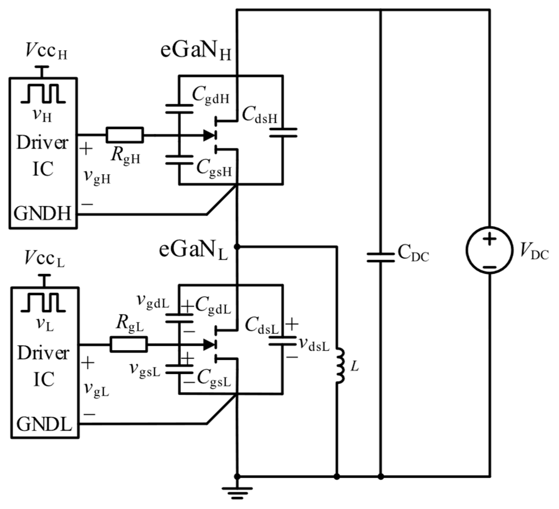
Figure 1. Schematic diagram of the eGaNH turn-on in a half-bridge circuit.
Jlpea 15 00038 g001
Figure 2. Proposed gate driver topology.
Jlpea 15 00038 g002
Figure 3. Timing diagram of proposed gate driver.
Jlpea 15 00038 g003
Figure 4. Gate driver modal diagram. (a) M1: turn-on phase; (b) M2: transition phase; (c) M3: positive crosstalk suppression phase; and (d) M4: negative crosstalk suppression phase.
Jlpea 15 00038 g004
Figure 5. Positive crosstalk suppression phase equivalent circuit.
Jlpea 15 00038 g005
Figure 6. Negative crosstalk suppression phase equivalent circuit.
Jlpea 15 00038 g006
Figure 7. Effect of R1 on the peak of the negative crosstalk.
Jlpea 15 00038 g007
Figure 8. Effect of different R1 on gate source oscillation.
Jlpea 15 00038 g008
Figure 9. Double-pulse test platform. (a) Mechanism diagram; (b) experiment platform.
Jlpea 15 00038 g009
Figure 10. The drain-source waveforms before and after adding the RC snubber.
Jlpea 15 00038 g010
Figure 11. The gate voltage oscillation under different values of R1.
Jlpea 15 00038 g011
Figure 12. Double-pulse test results. (a) Conventional gate driver; (b) proposed gate driver.
Jlpea 15 00038 g012
Figure 13. The turn-on waveforms. (a) Conventional gate driver; (b) proposed gate driver.
Jlpea 15 00038 g013
Figure 14. The turn-off waveforms. (a) Conventional gate driver; (b) proposed gate driver.
Jlpea 15 00038 g014
Figure 15. Synchronous Buck test platform. (a) Mechanism diagram; (b) experiment platform.
Jlpea 15 00038 g015
Figure 16. Synchronous Buck test results. (a) Conventional gate driver; (b) proposed gate driver.
Jlpea 15 00038 g016
Table 1. Comparison of different suppression circuits.
CircuitsReducing Device Turn-on SpeedExacerbating Negative CrosstalkIncreasing Control Complexity
In [23]YesYesNo
In [24]YesNoNo
In [27]NoNoYes
In [28]NoYesNo
In [29]NoNoYes
This paperNoNoNo
Disclaimer/Publisher’s Note: The statements, opinions and data contained in all publications are solely those of the individual author(s) and contributor(s) and not of MDPI and/or the editor(s). MDPI and/or the editor(s) disclaim responsibility for any injury to people or property resulting from any ideas, methods, instructions or products referred to in the content.